
pup joint drill pipe free sample
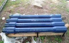
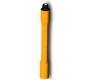
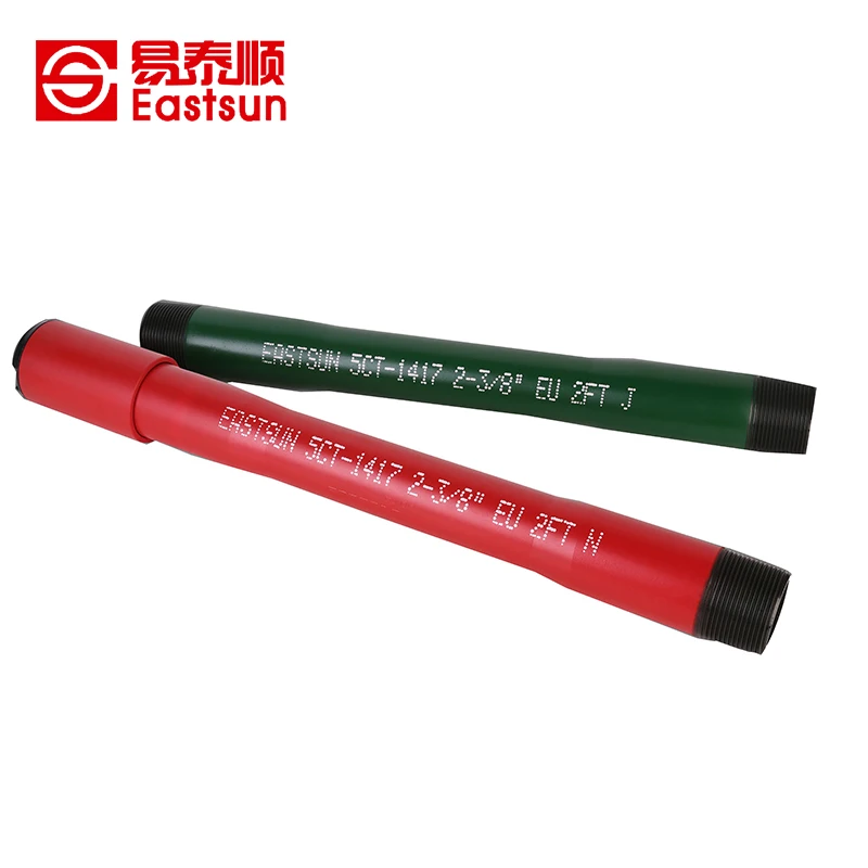
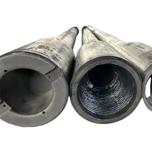
It is a short drill pipe used to adjust the overall length of drill string. The surface of Drill Pipe Pup joint looks like a smaller version of joint of drill pipe.
The minimum yield strength of Drill Pipe Pup Joint is 120000 PSI, just like the Tool Joint of the Drill Pipe. We manufacture Drill Pipe Pup Joints of all sizes, grades, and thread profiles to meet any custom requirements.
All our products have passed the ISO certification and API certifications.We have become the reliable exporter of Drill Pipe Pup Joint in India. Our products are tested numerous times under technical guidance and are made from best quality material.
The RIG will be mobilized from XXX to XXX. The rig will be moored in approximately xxx’ water depth. A string of 36” x 1.5” and 1.0" wall structure pipe will be jetted to xxx’ TVD / MD (xxx’ BML). The shallow hazards survey indicates possible low risk shallow gas potential from the mudline to approx. xxx’ TVD (xxx’ BML) and negligible to moderate risk shallow water flow potential at xxx’ TVD / MD (xxx’ BML).
After jetting the 36” structure pipe to the desired depth, the Drill Ahead Tool (DAT) will be used to drill 26” hole to xxx’ TVD / MD (xxx’ BML) and 20” casing will be run and cemented. The shallow water flow study indicates only low to moderate potential for over-pressured sands through this interval. Should a shallow flow be encountered while drilling riserless, 16.0 ppg kill mud will be available on the rig to control any such flow. After running and cementing 20” casing, the subsea BOP stack and riser will be run and tested. Prior to drilling out of the 20” casing, the hole will be displaced with 10.0 ppg synthetic based mud. A LOT of 10.7 ppg is expected at the 20” casing shoe. LWD (GR/RES/APWD/DIR) will be utilized in this hole section.
A 17’’ x 20” hole will be drilled to xxx’ TVD / MD and 16” casing will be run and cemented. This casing string is being set at this depth based on pore pressure and frac gradient. The expected mud weight at casing point is 10.4 ppg and the expected LOT at the 16” casing shoe is 12.4 ppg EMW. LWD (GR/RES/APWD/DIR) will be utilized in this hole section.
A 14 1/2’’ x 17 1/2” hole will be drilled to xxx’ TVD / xxx’ MD. The KOP for the directional work is planned at 7300" TVD/MD. A major azimuth change while building hole angle will be accomplished in this section using rotary steerable tools. A full string of 13 5/8” casing will be set. The expected mud weight at casing point is 12.0 ppg and the expected LOT at the 13 5/8” casing shoe is 14.2 ppg EMW. LWD (GR/RES/APWD/DIR) will be utilized in this hole section.
A 12 1/4’’ x 15" directional hole will then be drilled utilizing rotary steerable tools and LWD (GR/RES/APWD/DEN/NEUT/DIR) to xxx" TVD / xxx" MD. The 1st target zone will be encountered in this hole section at xxx" TVD. A wireline logging program consisting of GR/Dipole Sonic, RCI, and SWC will be run in this hole section. An 9 7/8" liner will be set in this hole section. The expected mud weight at casing point is 13.0 ppg and the expected LOT at the 11 7/8” casing shoe is 14.9 ppg EMW.
A 9 7/8’’ x 12 1/4" directional hole will then be drilled utilizing rotary steerable tools and LWD (GR/RES/APWD/DEN/NEUT/DIR) to xxx" TVD / xxx" MD. The primary target zones will be encountered in this hole section at xxx" TVD and xxx" TVD. A wireline logging program consisting of GR/Dipole Sonic, RCI, and SWC will be run in this hole section. A 9 7/8" liner will be set in this hole section. The expected mud weight at casing point is 14.4 ppg and the expected LOT at the 9 7/8” casing shoe is 15.8 ppg EMW.
An 8-1/2’’ hole will then be drilled to TD at xxx’ TVD / xxx’ MD utilizing rotary steerable tools and LWD (GR/RES/APWD/DEN/NEUT/DIR). The lower target zones will be encountered in this hole section at 14110" TVD and 14506" TVD. A wireline logging program consisting of GR/Dipole Sonic, RCI, SWC, MRILL, Earth Imager, and Check Shot will be run in this hole section. The expected mud weight at TD is
DWOP exercises will be conducted with drilling contractor personnel, service company personnel, COMPANY drilling supervisors and engineering staff prior to spud.
Pretension anchor chains to Contractor’s specifications for the rig. The rig will then ballast to drilling draft, and storm tension the mooring system.
The COMPANY Drilling Supervisors, Logistics Coordinator and Drilling Superintendent will prepare an initial “Required Personnel and Equipment” load-out list.
Verify 36" casing and jetting assembly tallies to ensure bit is no more than 6-8" outside the casing shoe. Adjust BHA length by the use of drill pipe pup joints and/or by cutting the 36" beveled end to fit.
P/U and stand back drill pipe and inner jetting assembly with a rock 26" bit. P/U CADA (Cam-Actuated Drill Ahead) running tool, M/U on wellhead housing and stand back.
P/U joint with beveled end x Vetco RL-4RB pin and run through rotary. Clean threads and apply AP-5 grease or lead-free API modified casing dope. Do not use any use API or other metallic- base thread compound.
Run required joints to allow 280" of penetration BML with 12" of stick up with the gas/mud mat at the ML. Make up connection and torque to recommended optimum torque. (See detailed VETCO procedure in the specific casing program section) Clean threads and apply API modified casing dope.
Record the following data on a basis: Time to jet 5", WOB, gpm, psi, comments, and notations on pipe reciprocation (when and how much the pipe was reciprocated) and the pumping of sweeps (volume and viscosity). Also note any overpull while working pipe.
Slack off weight and ensure casing is stable and remains straight. Record final bull"s eye level. Notify Drilling Superintendent if it is greater than 1.0o.
Release Vetco CADA and continue drilling next hole section as per this program. Upon pulling out of the hole, CADA will be lifted by the inner string without a special operation.
Pump 50 bbl (or slugging pit volume) hi-vis (FV > 100 sec) sweeps of seawater and prehydrated bentonite at each connection (more frequently if needed) and 50 bbl (or slugging pit volume) hi-vis pill at each half stand drilled.
Ensure MWD survey and bulls-eye indicates a wellbore angle of 1.0o or less. If 1.0o angle is exceeded, check the rig offset and consult with the Drilling Superintendent.
Shut down pumping and monitor well for flow with ROV. If well is still flowing, continue mud weight increase to kill the flow. Once well is dead, options will be discussed with members of the extended drilling team.
If a water flow is encountered, attempt to determine relative severity of flow. If water flow is minimal, consideration will be made to continue drilling to the 20” casing point. If flow is severe, increasing the mud weight or a dynamic kill will be considered. In either case, contact the COMPANY drilling staff to discuss options.
Lost circulation could occur if high annular loading results in an EMW greater than fracture gradient. Monitor APWD to determine ECD. Control drill this section at <100 ft/hr using as high of flow rates as practicable. Close observation to return flow via ROV is the only way to qualitatively tell if partial or full losses happen to occur.
Make up WHRT to 20" WH joint (with nominal seat protector and sufficient inner cement stinger to protrude from WH extension joint). Lay out on pipe rack or catwalk.
Install 2 centralizers with 1 stop collar for each centralizer on each of the bottom 3 joints. Install 1 centralizer with 1 stop collar at mid-joint on each of the next 3 joints. A total of 9 centralizers are to be run.
Collapse Caution: It is imperative that the casing string and drill pipe running string be full of fluid while running. Once the 20” shoe has entered the 36” Low Pressure Wellhead Housing, pump at least 1-1/2 casing volumes to assure that the strings are full.
Before making up WH joint, install a key-slot plate, bowl, and slips on top of the 20" casing. Pick up the 5 1/2" 21.90 ppf DP inner cementing string.
Continue running the casing on drill pipe to the mud line, filling the drill pipe every 5 stands. See Figure No. 2 at the end of this section for running weights and tensile capacities.
Monitor 20" movement at the WH with the ROV. Ensure drill pipe movement at the rig floor is consistent with casing movement at the wellhead to avoid buckling the 20" casing.
a) Record hook load every joint while running riser. Also record weights for the TDS/Traveling Block, riser running tool, tensioning ring (if not integral to telescopic joint), and diverter housing/upper flex joint. Send data to Drilling Engineer for review.
d) Pick up slip joint (closed) and landing joint and record buoyed weight of the BOPS and riser. Report weight of BOP and riser on daily drilling report. Notify office immediately if actual weight and estimated riser weight figures differ by more than 30 kips.
Test wellhead connector, shear rams, and casing to 250 / 3970 psi surface pressure while laying down the landing joint. Pressure must not decline by more than 10% in 30 minutes.
20" - 25" for rat hole is sufficient below long strings of casing, and 5" is sufficient below the liners. This limits the length of oversized, open hole below casing shoes where cuttings can accumulate. It also prevents excessive cement slump that can detrimentally effect the shoe test upon drilling out that can be a problem given the recommended cement slurry densities vs. the planned section TD MWs.
Drill with a minimum of 120 rpm with the Baker Autotrack system. If possible increase to 150 – 180 rpm. Balance ECD with the higher RPM. Watch for vibrations at the higher RPM and backoff the rpm to remove excessive vibrations.
When pumping a sweep pull the bit off bottom prior to the sweep exiting the bit. Ensure the drill string is at least 60 RPM while the sweep exits the bit. Increase the drill string rotation to a minimum of 120 RPM while pumping the maximum GPM while the sweep is moving up the annulus. Consider pumping piggyback sweeps by using a low vis then high vis sweep.
Always CBU with a maximum pump rate and maximum RPM (if possible above 150 RPM) while reciprocating the pipe. It may take up to 4 times bottoms up to clean the hole. Don’t just circulate a predetermined volume (ie 1.5 bottoms up) but circulate until the hole is clean. Don’t substitute reduced circulating time with the thought that we can backream if we see a problem.
Pumping out of the hole without drill pipe rotation is generally unacceptable and leads to backreaming conditions which often leads to packoffs and lost circulation. Pumping out without rotation can cause a cuttings bed above the BHA. If pumping is needed consider TIH a few stands and maximize GPM and rpm while pumping. Circulate clean then POOH without the pumps or rotation.
Before drilling the shoe, break circulation and circulate prior to taking slow pump rates. Check and record choke and kill line friction pressures. Perform power choke drill.
Drill out 10" of new hole. To avoid packing-off below the surface casing, pump a 200 bbl x 200 vis super-sweep (to clear the rat hole below the 20" casing) while mechanically disturbing the rat hole area by rotating a bit/stabilizer across the area at high rpm.
Once a LOT is obtained and drilling commences, pump 100 bbl x 200 vis supersweeps as necessary but at least prior to connections for 1st 300" of 17 ½" x 20" hole drilled.
Protech/Centerform composite centralizers will be Installed on the 3 joints to run as the shoe track and the 2 joints immediately above. 2 backup joints will also have the centralizers.
Collapse Caution: It is imperative that the casing string and drill pipe running string be full of fluid while running. Once the 16” shoe has entered the wellhead housing, pump at least 1 1/2 casing volumes to assure that the strings are full.
After landing in the casing hanger, makeup the ATC Cement head on drillpipe and begin pumping to close the diverter. The 2 1/4" ball will be on the seat in the Diverter Sub, pressure up to 1000 psi and hold same for 2 to 3 minutes. Continue to increase pump pressure until the ball yields the seat at 2200 to 2600 psi.
Before drilling the shoe, break circulation and circulate prior to taking slow pump rates. Check and record choke and kill line friction pressures. Perform power choke drill.
Drill out 10" of new hole. To avoid packing-off below the surface casing, pump a 200 bbl x 200 vis super-sweep (to clear the rat hole below the 16" casing) while mechanically disturbing the rat hole area by rotating a bit/stabilizer across the area at high rpm.
Once a LOT is obtained and drilling commences, pump 100 bbl x 200 vis supersweeps as necessary but at least prior to connections for 1st 300" of 14 1/2" x 17" hole drilled.
Drill hole to fit casing tally with 20" - 25" of rat hole below casing shoe. Do not drill more than 50" beyond APD shoe depth, 9600" TVD / 9692" MD RKB.
Protech/Centerform composite centralizers will be Installed on the 3 joints to run as the shoe track and the 2 joints immediately above. 2 joints to be run below the casing hanger will also have the centralizers installed. 2 backup joints will also have the centralizers.
After landing in the casing hanger, makeup the ATC Cement head on drillpipe and begin pumping to close the diverter. The 2 1/4" ball will be on the seat in the Diverter Sub, pressure up to 1000 psi and hold same for 2 to 3 minutes. Continue to increase pump pressure until the ball yields the seat at 2200 to 2600 psi.
POOH SLM and rabbit the DP using a 2 5/8” or greater OD drill pipe drift with +-120’ of wire attached and recover drift. Lay out any joints of drill pipe that do not drift. Compare to previous tally.
a) Protech/Centerform composite centralizers will be Installed on the 3 joints to run as the shoe track and the 2 joints immediately above. 2 backup joints will also have the centralizers.
g) If necessary, place one pup joint with a radioactive tag approximately 300" above each reservoir to flag the sands. Pup joint placement should specified in the program addendum.
Make up liner hanger assembly. LEAVING ROTARY SLIPS SET ON LINER JOINT, pick up approximately 3 feet to verify that the setting tool and all connections are properly torqued up. Once this has been done, pull slips, slack off until PBR sleeve is accessible from the rig floor. Fill the Floating Junk Bonnet with clean water. DO NOT SET SLIPS ON SETTING SLEEVE / PBR. SET DRILL PIPE SLIPS ON SETTING TOOL LIFT SUB. Make up stand of drill pipe to the liner hanger assembly running tool and lower assembly into well. Record liner weight.
If Liner rotation is anticipated being required in open hole, calculate maximum drill down torque. Liner thread maximum make-up torque, plus rotating torque established at the casing shoe on last trip out of the hole (Step 15 above) minus 20% safety factor = maximum drill down torque. (Rotate slowly at the shoe prior to entering open hole and record minimum torque required to maintain sustained rotation. This torque to be used as reference.
When the liner is one stand off bottom, screw the Top Drive in and start pumping slowly to close the ATC Diverter Sub. Keep the pipe moving down hole during this operation. The 1 3/4" ball will be on the seat so pressure up to 600 psi slowly and hold the same for 2 or 3 minutes. Then continue to increase the pump pressure until the ball yields the seat (1500-1800 psi). Note: You will be TIH very slowly when you perform these steps.
Calculate amount of slack off required to transfer all the liner weight plus 30,000 lbs. of drill pipe weight onto the liner hanger. Space out drill string to put the Cementing Head a minimum of that distance from the rig floor once hanger is hung off and weight slacked off.
Establish pick up and slack off weights. Reciprocate liner while circulating and conditioning mud / hole. (If well conditions permit, and operator has given approval, it is recommended that the pipe be reciprocated during the mud / hole conditioning. Ensure that the reciprocation stroke is not long enough to uncover any formation that must be isolated. This will ensure that inadvertently sticking pipe will not leave that formation uncovered. (It is imperative that the driller understand that the reciprocation stroke be a slow steady movement to prevent harmful pressure surges.)
Shut down circulation. With 10-20,000 lb. of drill string weight down on liner hanger, rotate 6-8 torque free turns to the right to release setting tool from the liner. Pick up stretch in pipe plus 5"-10" to see liner weight loss ensuring that setting tool is released from the liner. Note: Ensure that setting tool is not picked up high enough to remove packer actuator sub from the PBR extension. (Double check pick up on slick joint and Floating Junk Bonnet polish nipple)
Set 30,000 lb. of drill string weight back down on liner hanger, to prevent pump out forces of cement job from inadvertently pumping the setting tool out of the liner. Prepare to cement. (Note: Slack off weight will vary from job to job. The Weatherford serviceman will figure his pump out forces on setting tool and set down sufficient weight to overcome those pump out forces)
Circulate and condition the drilling fluid for the upcoming cement job. Recommend not circulating above 30 strokes per minute until the thick mud is above the liner assembly. Circulate bottoms up (minimum 2 x bottoms up from TD to liner top). Boost riser.
Release the drillpipe dart at the tail of cement. When this dart leaves the cement head we will again see a 1500-2200 psi pressure increase as the dart exits the PLI. Minimum pump rate is 5 bpm at all times.
Displacement will be with mud. NOTE: IF SYNTHETIC DRILLING FLUIDS ARE BEING USED COMPRESSIBILITY FACTORS, IF APPLICABLE, MUST BE ENTERED INTO DISPLACEMENT FIGURES. CONSULT WITH OPERATOR RIG SUPERINTENDENT AND /OR MUD ENGINEER TO OBTAIN THIS INFORMATION.
Approximately 5 barrels prior to the drillpipe dart reaching the ATC Diverter Sub slow the pump rate to 5 bpm . The pressure required to yield the seat with the drillpipe dart should range from 1500 - 2000 psi (above the circulating pressure). After yielding the seat the drillpipe dart will latch the liner wiper plug. The pressure required to release the liner wiper plug will range from 1500 - 2000 psi (above the circulating pressure). Record pressure required to shear the plug. Continue with the displacement.
Set down minimum of 40000 lbs. (at liner top) to shear pins and energize the TSP packer (The packer actuator sub has rotational capability. Rotate drill string slowly to the right to change friction points and work weight down to the packer. Up to 100000 lbs. can be used to set packer if necessary.
Pick up setting string leaving the end of the setting tool right at the liner top Begin reversing out slowly. Once returns are obtained, pick up slowly until the end of the running tool is approximately 5 feet above the liner top. Increase pump rate and continue to pick up slowly until the end of the running tool is 10-15’ above the liner top. Once sufficient fluid has been reversed out to ensure that all excess cement (Calculated Volume) is out of annulus and either at surface or at least 2,000’ from the end of the setting tool (inside drill pipe), slow pump rate to 1-2 barrels per minute. Slowly slack off setting string inserting the end of slick stinger back into the end of the PBR tie- back extension at least 5-7 ft. Continue circulating for 3-5 minutes and then slowly pick up leaving the slick stinger 5-10 ft above the liner top. Increase pump to desired rate and complete reversing out. Reverse out two drill pipe volumes or until no cement returns are observed. Limit circulating pressure to psi while reversing out to prevent overloading the liner hanger. PRIOR TO JOB VERIFY WITH OPERATOR’S HOUSTON OFFICE THE INTENT TO REVERSE OUT EXCESS CEMENT. VERIFY WITH WEATHERFORD SERVICEMAN LIMITING CIRCULATION PRESSURES.
Pick up and RIH with jet sub, WBRT, and test-type 9 5/8" wear bushing. Wash WH thoroughly with jet sub and jet nozzle joint. Install wear bushing. If seawater was used to displace cement: Circulate out NAF mud from the upper wellhead, BOPS, riser, and choke, kill and booster lines with seawater.
POOH SLM and rabbit the DP using a 2 5/8” or greater OD drill pipe drift with +-120’ of wire attached and recover drift. Lay out any joints of drill pipe that do not drift. Compare to previous tally.
Protech/Centerform composite centralizers will be Installed on each joint on each joint of casing at an interval of 1 per joint from the shoe track to 500" above the top of Galt 70 target.
Place one pup joint with a radioactive tag approximately 300" above each reservoir to flag the sands. Pup joint placement should specified in the program addendum.
Make up liner hanger assembly. LEAVING ROTARY SLIPS SET ON LINER JOINT, pick up approximately 3 feet to verify that the setting tool and all connections are properly torqued up. Once this has been done, pull slips, slack off until PBR sleeve is accessible from the rig floor. Fill the Floating Junk Bonnet with clean water. DO NOT SET SLIPS ON SETTING SLEEVE / PBR. SET DRILL PIPE SLIPS ON SETTING TOOL LIFT SUB. Make up stand of drill pipe to the liner hanger assembly running tool and lower assembly into well. Record liner weight.
If Liner rotation is anticipated being required in open hole, calculate maximum drill down torque. Liner thread maximum make-up torque, plus rotating torque established at the casing shoe on last trip out of the hole (Step 15 above) minus 20% safety factor = maximum drill down torque. (Rotate slowly at the shoe prior to entering open hole and record minimum torque required to maintain sustained rotation. This torque to be used as reference.
When the liner is one stand off bottom, screw the Top Drive in and start pumping slowly to close the ATC Diverter Sub. Keep the pipe moving down hole during this operation. The 1 3/4" ball will be on the seat so pressure up to 600 psi slowly and hold the same for 2 or 3 minutes. Then continue to increase the pump pressure until the ball yields the seat (1500-1800 psi). Note: You will be TIH very slowly when you perform these steps.
Calculate amount of slack off required to transfer all the liner weight plus 30,000 lbs. of drill pipe weight onto the liner hanger. Space out drill string to put the Cementing Head a minimum of that distance from the rig floor once hanger is hung off and weight slacked off.
Establish pick up and slack off weights. Reciprocate liner while circulating and conditioning mud / hole. (If well conditions permit, and operator has given approval, it is recommended that the pipe be reciprocated during the mud / hole conditioning. Ensure that the reciprocation stroke is not long enough to uncover any formation that must be isolated. This will ensure that inadvertently sticking pipe will not leave that formation uncovered. (It is imperative that the driller understand that the reciprocation stroke be a slow steady movement to prevent harmful pressure surges.)
Shut down circulation. With 10-20,000 lb. of drill string weight down on liner hanger, rotate 6-8 torque free turns to the right to release setting tool from the liner. Pick up stretch in pipe plus 5"-10" to see liner weight loss ensuring that setting tool is released from the liner. Note: Ensure that setting tool is not picked up high enough to remove packer actuator sub from the PBR extension. (Double check pick up on slick joint and Floating Junk Bonnet polish nipple)
Set 30,000 lb. of drill string weight back down on liner hanger, to prevent pump out forces of cement job from inadvertently pumping the setting tool out of the liner. Prepare to cement. (Note: Slack off weight will vary from job to job. The Weatherford serviceman will figure his pump out forces on setting tool and set down sufficient weight to overcome those pump out forces)
Circulate and condition the drilling fluid for the upcoming cement job. Recommend not circulating above 30 strokes per minute until the thick mud is above the liner assembly. Circulate bottoms up (minimum 2 x bottoms up from TD to liner top). Boost riser.
Release the drillpipe dart at the tail of cement. When this dart leaves the cement head we will again see a 1500-2200 psi pressure increase as the dart exits the PLI. Minimum pump rate is 5 bpm at all times.
Displacement will be with mud. NOTE: IF SYNTHETIC DRILLING FLUIDS ARE BEING USED COMPRESSIBILITY FACTORS, IF APPLICABLE, MUST BE ENTERED INTO DISPLACEMENT FIGURES. CONSULT WITH OPERATOR RIG SUPERINTENDENT AND /OR MUD ENGINEER TO OBTAIN THIS INFORMATION.
Approximately 5 barrels prior to the drillpipe dart reaching the ATC Diverter Sub slow the pump rate to 5 bpm . The pressure required to yield the seat with the drillpipe dart should range from 1500 - 2000 psi (above the circulating pressure). After yielding the seat the drillpipe dart will latch the liner wiper plug. The pressure required to release the liner wiper plug will range from 1500 - 2000 psi (above the circulating pressure). Record pressure required to shear the plug. Continue with the displacement.
Set down minimum of 40000 lbs. (at liner top) to shear pins and energize the TSP packer (The packer actuator sub has rotational capability. Rotate drill string slowly to the right to change friction points and work weight down to the packer. Up to 100000 lbs. can be used to set packer if necessary.
Pick up setting string leaving the end of the setting tool right at the liner top Begin reversing out slowly. Once returns are obtained, pick up slowly until the end of the running tool is approximately 5 feet above the liner top. Increase pump rate and continue to pick up slowly until the end of the running tool is 10-15’ above the liner top. Once sufficient fluid has been reversed out to ensure that all excess cement (Calculated Volume) is out of annulus and either at surface or at least 2,000’ from the end of the setting tool (inside drill pipe), slow pump rate to 1-2 barrels per minute. Slowly slack off setting string inserting the end of slick stinger back into the end of the PBR tie- back extension at least 5-7 ft. Continue circulating for 3-5 minutes and then slowly pick up leaving the slick stinger 5-10 ft above the liner top. Increase pump to desired rate and complete reversing out. Reverse out two drill pipe volumes or until no cement returns are observed. Limit circulating pressure to psi while reversing out to prevent overloading the liner hanger. PRIOR TO JOB VERIFY WITH OPERATOR’S HOUSTON OFFICE THE INTENT TO REVERSE OUT EXCESS CEMENT. VERIFY WITH WEATHERFORD SERVICEMAN LIMITING CIRCULATION PRESSURES.
Find parts you need to repair or maintain your machines. At Alibaba.com, you can shop for pup joint drill pipe at affordable rates to tackle new obstacles and challenges. In the ever-changing industry, you can find what you need and speak to the supplier directly. Thanks to Alibaba’s collection of wholesale pup joint drill pipe you also get to buy these parts at lower prices, which means you can explore new levels every day more comfortably. From bulldozers to dragline excavators, wheel tractor scrapers to shotcrete machines, any part you need for a heavy-duty mining machinery; you can find it at Alibaba.com.
Looking for purpose-built machine parts? Find them at Alibaba.com. From new components to used parts straight from the manufacturers. Plus, if you need custom-made pieces, you can chat with the supplier, give specifications and wait on delivery. From stone crushers to excavator undercarriage parts, buckets, and even drill bits to get you through the rocks, the pup joint drill pipe from Alibaba offers you the chance to continue operating without a hitch. Whether you are looking to introduce concrete into the rock walls for more consistency and safety during mining, then pup joint drill pipe that goes at wholesale prices at Alibaba will be an excellent addition to your machinery.
Before buying a component, you’d want the equipment to suit your application and offer value. The list of pup joint drill pipe at Alibaba.com lets you dig into earth deposits, and the compare tool checks out other similar parts to give you the information you need to make a purchasing decision. You’ll get wholesale pup joint drill pipe that specializes in mining, with reinforced chassis, and run on more powerful engines. Whether you want to transport minerals or the workers to the mining site, introduce explosives or arms to help you remove materials from your mine pits, Alibaba.com has it all.
The initial operation was to move the previously assembled reentry cone off of the moonpool doors, lay out the upper guide horn, and pick up eight drill collars from the forward pipe rack. The BHA and other drill string components were strapped (measured) and drifted (through bore clearance check) as they were made up and lowered through the rig floor. The camera/sonar system was deployed and the bit was observed tagging the seafloor at 2667.5 meters below rig floor (mbrf) as measured from the dual elevator stool (DES). This depth was later adjusted to 2667.3 mbrf.
A jet-in test to verify how much 20 inch casing could be washed beneath the reentry cone was initiated using an 181/2 inch tricone drill bit fitted with three number 16 jets. The jet-in test required more strokes per minute with the rig circulating pumps and higher weight on bit (WOB) than was required for the jet-in test conducted for Hole 1026B (ODP Leg 168) located ~1 nmi away. The jet-in test was terminated after 5.75 h at 41.4 mbsf. After recovering the jet-in assembly we discovered that one of the bit jets was plugged. This may partially explain the higher pump pressures and slower jetting process; however, we decided to reduce the length of 20 inch casing from ~75 to ~39 m.
After moving the reentry cone back over center in the moonpool, the rig floor was prepared for running 20 inch casing. This casing assembly consisted of a shoe joint cut to the appropriate length and welded out to a standard 20 inch Texas pattern casing shoe, two joints of 20 inch casing (94 lb/ft; K-55; range-3; buttress thread), a standard 20 inch casing pup joint, and a 20 inch Dril-Quip (DQ) casing hanger. The hanger was latched into the reentry cone bore, and latch ring engagement was verified by visually observing that the latch ring was in the appropriate position as viewed through the disengagement holes. Because the typical "audible" latch ring engagement snapping sound was not heard, the hanger was tack-welded in four places in the casing hanger flutes. This was done as added insurance against an inadvertent disengagement during the trip to the seafloor. After assembling the BHA, the DQ casing running tool was made up to the 20 inch casing hanger and the entire assembly was ready for lowering. At 1600 h on 29 June, Hole U1301A was spudded as the 20 inch casing shoe tagged the seafloor. Jetting of the 20 inch conductor casing proceeded well, and 7 h later we landed and released the reentry cone base at the seafloor. Release of the DQ running tool was executed perfectly at 2300 h and the drill string was tripped back to the surface.
The first change to the initial operations plan for this site came with the drilling of the hole for the 16 inch casing string. The original plan called for drilling a nominal 211/2 inch diameter hole using a bicentered reamer (Downhole Design, Inc. [DDI]; B182X215). This tool was used successfully during ODP Leg 206 to drill two basement holes. In talking with members of the drill crew and the ODP Operations Superintendent for that leg we learned that the tool was not without problems. They were able to drill successfully in basement rock; however, the 97/8 inch tricone bit used as a pilot for the bicentered reamer assembly catastrophically failed twice, leaving bit cones in the hole. This was attributed to lateral loading of the bit during the bicenter functioning of the reamer head. For our expedition, DDI provided a 97/8 inch stabilizer sub to run directly above the pilot bit. In addition, a specially designed 97/8 inch pilot "wobble" bit was provided to replace the conventional 97/8 inch tricone bit. The Leg 206 crew also indicated that the bicenter reamer did not drill a very good hole in the softer sediments overlying the hard basement rock. It was believed that this may have contributed to problems emplacing the 16 inch casing strings on Leg 206. With this added knowledge, we modified the operations plan for Expedition 301. We decided to deploy a more conventional "arm style" underreamer to drill the sediment section of the hole to be followed, after a drill string round trip, with the bicenter reamer assembly to drill the upper ~15 m of basement. We decided to accept the penalty of another pipe trip in order to avoid both the problems experienced on Leg 206 and having to drill with the conventional "arm" style underreamer in basement rock, which historically has had integrity problems that led to underreamer failure.
The drilling assembly was lowered, the camera/sonar system was deployed, and Hole U1301A was reentered for the first time after <5 min. Once inside the 20 inch casing the top drive was picked up, the camera was recovered, and drilling commenced at 1530 h. After an initial slow advance of 6 m directly below the 20 inch casing shoe (to keep from opening the underreamer arms inside the casing), the underreamer was opened up and drilling continued to 262.2 mbsf. An abrupt change in rate of penetration (ROP), coupled with the typical "basalt bounce" associated with hard rock drilling, was a clear indication that we had reached our basement target originally projected to be at ~275 mbsf. Overall net ROP (including connection time) with the conventional underreamer in sediment was 16.5 m/h. Actual drilling ROP was 22.3 m/h. Control drilling techniques were employed to ensure that a good quality hole was obtained.
The hole was swept with 50 bbl of sepiolite drilling mud. The drill string was recovered and the underreamer and pilot bit were laid out by 1130 h on 1 July.
A DDI bicenter reamer (BCR; B182X215) assembly, including a 97/8 inch stabilizer and a 97/8 inch pilot wobble bit, was made up to the BHA and lowered to the seafloor. This BCR configuration is designed to drill a 211/2 inch diameter hole yet be able to pass through a diameter of 181/4 inchthis would allow it to safely pass through the 20 inch casing string, which has a nominal internal diameter (ID) of 191/8 inch. After another 5 min reentry, the drilling assembly was lowered to 233.7 mbsf without incident. The top drive was picked up and the pipe was lowered the remaining distance to the bottom of the hole. At 1900 h on 1 July basement drilling with the BCR commenced. Drilling proceeded well at first with 7.3 m of advance drilled at an average ROP of 1.5 m/h. The last 1.8 m only drilled at 0.6 m/h, and after sweeping the hole with 50 bbl of sepiolite mud a wiper trip back above the basement contact at 262.2 mbsf was made. Two more wiper trips were made through this interval interspersed with two more 50 bbl sepiolite mud sweeps. The lowermost 24 m of hole never did clean up adequately and it was felt that attempting to advance the hole further with this drilling assembly was not prudent and risked tool failure. Significantly elevated drilling torque, 450+ A rather than the earlier 150 A, led us to abandon further attempts at deepening the hole with the BCR assembly, and we elected to recover the drill string short of our original target depth of 272276 mbsf. The hole was displaced with sepiolite mud and the drill string was recovered on the rig floor at 1400 h on 2 July.
The subsea release (SSR) plug assembly was made up to the DQ casing running tool and secured in the derrick. After conducting a safety meeting, preparations were made for running 16 inch casing. The shoe joint was picked up and the cementing float shoe was attached to the lowermost joint of 16 inch casing. Another 19 joints of standard 16 inch (75 lb/ft buttress) casing were made up, and the 16 inch casing hanger was then attached to the top of the string. The casing running tool was engaged with the 16 inch casing hanger, and the string was lowered to 2643 mbrf and spaced out for reentry. Another quick reentry (10 min) was made into Hole U1301A at 0045 h on 3 July. The casing string was lowered without resistance to 2902 mbrf (234.3 mbsf), where the top drive was picked up. We continued washing down the casing to 2924 mbrf (256.3 mbsf) and the cementing manifold was picked up. The 16 inch hanger was landed and latch-in verified at 0315 h. The cementing operation proceeded smoothly with 18 bbl of 15.8 lb per gallon (ppg) cement mixed up and displaced downhole. The cementing dart landed at the proper amount of strokes (~1220) indicated by a standpipe pressure rise to 2600 psi. The SSR dart/wiper plug assembly also landed at the proper amount of strokes (~1600) and a pressure of 500 psi was maintained. After releasing the pressure at the standpipe, a check was made to confirm that no flowback was occurring. The cementing swivel hose was disconnected and, after 31/4 turns to the right, the casing running tool was released. The end of the drill string was pulled clear of the reentry cone and secured for a routine servicing of the drill line (slip and cut) prior to retrieving the drill string. By 1230 h the drill string was back on the rig floor. The casing running tool was detorqued and laid out with the SSR assembly.
A new 141/2 inch tricone drill bit (Varel type ETD617) was made up and six 81/4 inch drill collars were picked up from the forward tubular rack. A five-stand drilling BHA was assembled, which allowed us to drill 130 m past the 16 inch casing shoe without placing the tapered drill collar (TDC) in open hole. Therefore, the drilling assembly exposed to open hole would consist entirely of slickwall pipe (81/4 inch drill collars) all the way down to the top of the 143/4 inch tricone drill bit.
The drill string was lowered to 2658.9 mbrf, stopping to fill the pipe every 30 stands. After spacing out the drill string, another 5 min reentry was made into the Hole U1301A. After retrieving the camera system, the pipe was lowered an additional four stands and the top drive was picked up in preparation for drilling. At 2130 h on 3 July the top of the 16 inch wiper plug was contacted and we commenced drilling out the wiper plug, dart, and float shoe assembly. Once through the shoe, the hole cleaning continued to 270.3 mbsf (1.0 m off bottom) when the bit was 8.1 m into basement. Drilling operations then continued with the drilling of the 143/4 inch diameter hole for the 103/4 inch casing string.
At 0015 h on 5 July we terminated drilling the 143/4 inch hole at 3037.0 mbrf (369.7 mbsf). This was 107.5 m into basement. The upper ~42 m of basement drilled at 3.0 to 3.5 m/h. At a ~304 mbsf the ROP began to steadily increase to ~8.0 m/h and this continued to ~357 mbsf. Only a few relatively thin spots (<0.5 m) of 4 m/h drilling rates were interspersed through this interval. The zones of rapid penetration concerned us, and those fears proved to be well founded. The next 20+ h were spent fighting hole problems. Multiple wiper trips, reaming operations, mud sweeps, and so on were required before the hole eventually cleaned up to what we considered reasonable for attempting to emplace casing. The hole was displaced with sepiolite mud and at 2000 h on 5 July we made one final pipe trip up inside the 16 inch casing hanger at 259.3 mbsf. We then lowered the bit back into open hole without rotation or circulation. The bit reached 3016 mbrf (348.3 mbsf) before taking 20,000 lb weight. The driller then broke circulation and proceeded to wash down to bottom. The hole was swept one final time with 50 bbl of sepiolite and then displaced with sepiolite mud. The drill string was recovered on board by 0400 h on 6 July.
Twenty-seven joints of 101/2 inch casing (40.5 lb/ft; K-55; range 3; buttress thread) were made up with a standard Halliburton cementing float shoe on the bottom and a conventional DQ 103/4 inch casing hanger/pup joint at the top. After attaching the casing running tool, the casing assembly was lowered to the seafloor. Once the camera system could see the bottom, we reentered Hole U1301A with the casing string within 5 min (at 1415 h). Problems ensued almost immediately. The 103/4 inch casing shoe encountered resistance ~4 m below the 16 inch casing shoe (~3 m into basement). The casing was worked past this ledge, and by 2030 h we had managed to work the 103/4 inch casing to 355.6 mbsf or 93.2 m into basement. This was just 4.5 m shy of our hanger landing depth. With confidence mounting we shut down circulation and picked up the cementing manifold and swivel assembly. Once operations resumed (~16 min later) we found that we were unable to move the casing down any further. The hole appeared to be collapsing in above us, although we still were able to maintain uninhibited circulation. We not only could not pass 3023.3 mbrf (355.6 mbsf); we also had problems pulling back uphole (20,000 to 40,000 lb overpull). The casing could be pulled back up with overpull but would not go back down. After pulling the casing shoe back to 309.3 mbsf (46.9 m into basement) all drilling parameters returned to normal. Speculation was that "ratchet" rocks fell in from above and would only allow movement in the upward direction. Once this material was below us the casing was once again free to move up or down freely. By 2400 h on 6 July the casing had been once again lowered to 3010.8 mbrf (343.1 mbsf). At this point the upper hole problems again prevented us from advancing any further. At 0400 h on 7 July we stopped attempting to land the casing and decided instead to recover the casing string, shorten it up considerably, and make Hole U1301A an installation to monitor uppermost basement.
After pulling the casing string back to the ship we laid out the casing hanger and then began to lay out the first of what was supposed to be a total of seven joints of 103/4 inch casing. The first joint was laid out correctly. The second joint appeared to be slightly bent. The next five joints were noticeably bent, so we continued on and checked the next two joints beyond the original number of joints we intended to take out of the casing string. The sixth joint was also bent, but from that point on the string was all right. All bent joints had been above the seafloor during the attempts at getting past the problem zone.
A single "replacement" joint of 103/4 inch casing was picked up and made part of the original casing string. All six of the recovered bent joints were marked and stored in the riser hold. The 103/4 inch casing hanger was then made up, the running tool was attached, the remainder of the BHA was assembled, and the 103/4 inch casing string was lowered for the second time. Space out for the new casing string was designed to place the casing shoe into the upper portion of basement above the zone of rapid ROP and fairly close to the sediment/basement interface so as to have the best chance of a good cement seal and limited lateral dispersion of the cement into the formation. We felt that attempting to place the 103/4 inch casing shoe too far into the upper "fractured" basement would risk not getting the cement to reach back up to the 16 inch casing shoe, which was essential for sealing the hole for the CORK hydrologic experiment. The objective of the shallow sampling hole was to sample the "upper" few tens of meters of basement; our planned 103/4 inch casing shoe depth would achieve this, and placing it deeper into the "upper" basement would not improve upon this goal.
The subsequent reentry of Hole U1301A was made more interesting than the previous ones due to a great cloud of drilling mud that was suspended in and around the reentry cone, significantly obscuring visibility. Instead of the camera, the sonar system was used primarily to locate the cone and was also a major contributor in helping to make the reentry itself. After 45 min, Hole U1301A was reentered for the sixth time and the shortened version of the 103/4 inch casing string was lowered into the hole and landed without incident, placing the 103/4 inch casing shoe at 277.1 mbsf, or 14.9 m into basement. Hanger latch engagement was confirmed with 15,000 lb of overpull, and the shoe was cemented in place with 10 bbl of 15.2 ppg class G cement. The cementing operation using the SSR system was completed without incident, and at 0035 h on 8 July the casing running tool was released. The initial phase of operations in Hole U1301A was completed with the recovery of the drill string at 0800 h on 8 July.
Hole U1301B was located only 36 m northeast of Hole U1301A, so the ship was offset in DP mode while the drill crew continued to retrieve the drill string. The scientists wanted to have Hole U1301B as close as technically possible for the potential of being able to investigate vertical flow. Because of the close proximity of the holes a jet-in test was considered unnecessary.
The newly painted reentry cone was moved over center in the moonpool, and the rig floor was prepared for running 20 inch casing. This assembly consisted of a shoe joint previously cut to the appropriate length and welded out to a standard 20 inch Texas pattern casing shoe, two joints of 20 inch casing (94 lb/ft; K-55; range-3; buttress thread), a standard 20 inch casing pup joint, and a 20 inch DQ casing hanger. The hanger was latched into the reentry cone and latch ring engagement was verified by visually observing that the latch ring was in the appropriate position as viewed through the disengagement holes. Unlike the previous 20 inch latch-in operation, this time the distinctive "audible snap" was heard as the latch ring engaged. After assembling the BHA, the casing running tool was made up to the 20 inch casing hanger and the entire assembly was ready for lowering. At 2000 h on 8 July, Hole U1301B was spudded as the 20 inch casing shoe tagged the seafloor. Jetting of the 20 inch conductor casing proceeded well, and 6.5 h later we landed and released the reentry cone base at the seafloor. Release of the DQ running tool was again executed perfectly, and by 0900 h on 9 July the drill string was back on board ship.
The same Smith 181/2 inch Model 2JS tricone drill bit (jetted with one number 16, and two number 24 nozzles) and the same HOC model DTU 1175 underreamer (outfitted with three number 12 jets) were made up and prepared for and running in the hole. As is customary, the underreamer was function-tested by pumping with a circulating head to visually observe that the underreamer arms would open correctly. Even with 90 spm and 900 psi pressure the arms failed to extend. At 1300 h on 9 July we decided to suspend operations long enough to rebuild the single set of large underreamers that we had on board. Drilling the hole only with the 181/2 inch bit was discussed and rejected, as was the use of the 211/2 inch BCR (per previous experience discussed earlier). The underreamer was torn down by placing the body vertically in the rotary table. The seals were replaced, and 3.75 h later the tool had been rebuilt and successfully function-tested.
The drilling assembly was lowered to the seafloor, the camera system was deployed, and the drill crew serviced the drill line (slip and cut). Prior to reentry we lowered the pipe and visually observed the bit tag the seafloor adjacent to the reentry cone. Seafloor depth for Hole U1301B was confirmed to be 1.0 m higher than Hole U1301A at 2666.5 mbrf. This depth was later adjusted to 2667.8 mbrf. Hole U1301B was reentered for the first time in virtually seconds. As the bit was lifted off the seafloor it swung directly over the reentry cone and the reentry was made at 2245 h on 9 July.
Once inside the 20 inch casing the top drive was picked up, the camera was recovered, and drilling commenced at 0015 h on 10 July. After an initial slow advance of ~9 m directly below the 20 inch casing shoe (to keep from opening the underreamer arms inside the casing), the underreamer was opened up and drilling continued to 2933.0 mbrf (265.2 mbsf). An abrupt change in ROP at 1015 h, coupled with the typical "basalt bounce" associated with hard rock drilling, was a clear indication that we had reached our basement target 4.1 m shallower than we did in Hole U1301A. The underreamer, with arm extension set at 20 inches, was installed ~8 m above the bit. The 181/2 inch tricone bit with the 20 inch underreamer above drilled the sediment at an average rate of 35.0 m/h. The average "net" ROP in sediment was ~23 m/h (including connection time). We continued drilling in basement to 2943.0 mbrf (275.2 mbsf). The ROP for the 181/2 inch bit in basement (first 8 m) was 3.6 m/h using a WOB of ~15,000 lb. An additional 2 m of basement was then drilled with the underreamer penetrating the top of basement, placing the depth of the 20 inch hole at 2935.0 mbrf (267.2 mbsf). The actual ROP for the 2 m of basement drilled with the 20 inch underreamer was ~1.3 m/h using a reduced WOB of 10,00012,000 lb. Other notable drilling parameters were rotation = 6070 rpm, two pumps at 80 spm each, and pump pressure = 14501475 psi.
We swept the hole with 50 bbl of sepiolite mud and then made another wiper trip to 2900.0 mbrf (232.2 mbsf) and back to TD. We checked the hole condition at that point by lowering the drilling assembly without pump or rotation until encountering a ledge at 2935.0 mbrf (267.2 mbsf). This was <1.0 m below our target depth for the 16 inch casing shoe of 267.5 mbsf and was considered too close for comfort. We therefore elected to drill an additional 1.0 m of hole into basement. With the 181/2 inch hole depth now at 2944.0 mbrf (276.2 mbsf) and the 20 inch hole depth at 2936.0 mbrf (268.2 mbsf) we again swept the hole with 50 bbl of sepiolite mud and proceeded to conduct one last hole inspection to 2900.0 mbrf (232.2 mbsf) and back to TD without rotation or circulating. This time the hole was deemed in acceptable condition for 16 inch casing deployment.
The hole was swept a final time with 50 bbl of sepiolite mud and then displaced with another 304 bbl of sepiolite prior to retrieving the drill string. When the drill string was recovered the underreamer arms were still in the expanded position. We were unable to retract the arms. The underreamer and drill bit assembly was laid out by 0615 h on 11 July.
By drilling the upper 3.0 m of basement with the underreamer assembly we eliminated the need for another drill string round trip to deploy the bicentered bit assembly. Therefore our attention turned to making up and deploying the 16 inch casing string. A total of 19 joints of 16 inch casing (75 lb/ft; K-55; range 3) was made up with a cementing float shoe on the bottom and a standard 16 inch casing hanger on the top. The special 16 inch seal bore pup joint was not used, however, because of insufficient clearance (0.015 inch per side) with the 103/4 inch seal sub assembly designed to mate with the seal bore hanger.
To enhance our chances of successfully landing the casing hanger we amended our operating procedures. We made up a single joint of drill pipe to the bottom of the cementing manifold. In this way we hoped to speed up the process of adding the cementing manifold to the drill string later. It was during this time that previously, with the circulation pumps shut down, we are most vulnerable to packing of the hole annulus and the attendant problems with getting the casing string moving downhole once again.
The casing string was lowered to the seafloor, the camera system was deployed, and Hole U1301B was reentered for the second time at 1620 h on 11 July. After picking up the top drive, the casing was lowered into open hole and the casing hanger landed without incident at 1800 h. Latch engagement was verified with 15,000 lb of overpull. The 16 inch casing shoe was subsequently cemented in place with 18 bbl of 15.2 ppg cement at a 270.9 mbsf. The casing running tool was released with 31/4 turns to the right and the drill string/cementing manifold were thoroughly flushed with seawater prior to retrieval.
At 0130 h on 12 July we began making up the 143/4 inch tricone drilling assembly. A five-stand BHA was run so that we could keep the top of the 81/4 inch drill collars inside casing and out of open hole. In this way we minimized our chances of getting stuck while drilling the 143/4 inch diameter hole.
Hole U1301B was reentered for the third time at 0700 h on 12 July, and by 1030 h the float shoe and cement were drilled out and the hole was cleaned up to TD at 2944.0 mbrf (276.2 mbsf). At 1030 h we began drilling the 143/4 inch hole in basement required for the 103/4 inch casing string.
Basement drilling was conducted using a new Varel 143/4 inch ETD617 tricone drill bit (SN174706) jetted with three number 20 nozzles. The first 50.0 m of basement drilling was achieved in 13.5 h at an average "net" drilling rate (including connection time) of 3.7 m/h. The actual ROP through this section varied from as much as 6.0 to <1.0 m/h. Drilling was uneventful until reaching 327.2 mbsf. While picking up to make a connection, the driller noted 20,000 lb of overpull and significantly elevated pump pressures. It appeared that the hole had packed off. The driller continued to fight hole problems including loss of rotation, loss of circulation, overpull, and elevated pump pressure for the next >11 h. Finally, at 1130 h on 13 July, the hole appeared to be stabilized and forward progress continued. By 1530 h the hole had been advanced to the target depth of 3018.0 mbrf (350.2 mbsf) or 85.0 m into basement.
Twenty nine joints of 103/4 inch casing (40.5 lb/ft; K-55; Range 3) were made up along with a cementing float shoe and the 103/4 inch casing hanger. Total string length was 342.50 m. The casing running tool was made up and lowered to the seafloor. The camera was deployed and Hole U1301B was reentered for the fourth time at 1140 h on 14 July. The casing was lowered to 2964.0 mbrf and the top drive was picked up. The casing was washed to 3002.0 mbrf (334.2 mbsf) without incident. After picking up the cementing manifold we found we could not pass 3002.0 mbrf. Nearly 7 h were spent attempting to move the casing further downhole but all efforts were in vain. The string was entirely free above 3000.0 mbrf but could not be moved any further down the hole. At 1930 h we abandoned our efforts to install the casing, laid out the cementing manifold, and retrieved the casing string. There were no problems or indications of drag or overpull identified while pulling the casing in open hole. By 0530 h on 15 July, the 103/4 inch casing string had been disassembled and stored away in the riser hold.
A 143/4 inch tricone bit and five-stand drilling BHA was assembled and lowered to the seafloor. Reentry number 5 was made into Hole U1301B in short order, and at 1015 h 15 July we began to lower the bit to 2965.0 mbrf, where the top drive was picked up. The bit was washed to 2998.0 mbrf (330.2 mbsf) before encountering any significant resistance. At that depth the driller noted that he was meeting resistance (taking weight). The next 6 h were spent washing, reaming, and pumping multiple sepiolite mud sweeps to clean and condition the hole once again from 2998.0 mbrf to TD at 3018.0 mbrf. By 2000 h on 15 July we were comfortable with the shape the hole was in. We then pulled the pipe back up into the 16 inch casing shoe and waited 1 h for the hole to equilibrate. No overpull or drag was encountered during the trip up to the casing shoe, which was a good sign. At 2130 h we began lowering the pipe slowly to TD with minimal pump (30 spm) and no rotation. At TD we swept the hole one final time with 50 bbl of sepiolite mud and pulled out of the hole. No significant resistance was encountered, and we felt certain that the last remaining vestiges of problem spots had been removed. By 0500 h on 16 July the bit was on deck and we began making up the 103/4 inch casing string for the second time.
The same casing string consisting of 29 joints of 103/4 inch (40.5 lb/ft; K-55; range 3) casing was made up along with a cementing float shoe and the 103/4 inch casing hanger. Total string length was held constant at 342.50 m. The DQ running tool was made up, and the casing was deployed via the drill string. The vibration-isolated television (VIT) camera was installed, and Hole U1301B was reentered for the sixth time at 1425 h on 16 July. The casing was run in hole to 2964.5 mbrf, and the top drive was picked up. Lowering continued to ~3005 m, where minor resistance was met. The casing was encouraged to move down another meter by increasing the pump strokes. The cementing manifold with a pre-made up drill pipe single was made up and the cementing hose was connected.
This new technique worked beautifully and mud pump circulation was shut down for only 2 min, 55 s. With the manifold in the string we resumed lowering casing and landed the casing hanger at 1615 h on 16 July 2004. Proper latch engagement was verified with 15,000 lb of overpull. The 103/4 inch casing shoe was cemented at 346.1 mbsf with 32 bbl of 15.2 to 15.8 ppg cement. Heavier cement was pumped at the shoe. The cement was displaced with the rig mud pumps, the cementing dart was released, and the SSR plug was landed with 500 psi. The pressure was vented at the standpipe manifold, and a check for backflow proved negative. The casing running tool was released with 31/4 turns of right-hand rotation and it was raised to 2657.0 mbrf. After flushing and laying out the cementing manifold, we set back the top drive and recovered the camera. Prior to retrieving the drill string, the drilling line was serviced (slip and cut). The pipe trip was completed while the ship moved to Hole 1026B. A positioning beacon (SN 2193; 14.0 KHz; 208 Db) was deployed at 2356 h, and by 0045 h on 17 July the casing running tool was detorqued and laid out, ending Hole U1301B for now.
The first operation during this occupation of Hole U1301B was to drill out the 103/4 inch casing shoe, the SSR plug/dart assembly, and any remaining cement. A 97/8 inch tricone drill bit was made up to a three-stand BHA and lowered to the seafloor.
Prior to reentry into Hole U1301A, we decided to conduct a thorough depth check in both Holes U1301A and U1301B. Using the drill string pipe tally and the camera system, we visually verified the seafloor depth, the depth for the top of the cuttings mound (at a single location), and the depth to the top rim of the installed reentry cones. By taking these measurements simultaneously over a 30 min period, we essentially eliminated tidal effects (Fig.
With the depth measurement exercise completed, Hole U1301A was reentered for the seventh time at 1940 h on 17 July. The camera was recovered back on board ship while the pipe was lowered into the hole run and the top drive was picked up. The float shoe was drilled out in 45 min and the bit was then lowered without rotation and without circulation to see how much unrestricted depth of hole was available. Tag depth was recorded at 2963.5 mbrf with 15,000 lb of weight set down. This equates to 296.2 mbsf, which is 34.0 m into basement or 19.1 m below the 103/4 inch casing shoe. The 97/8 inch drilling assembly was retrieved, and at 0315 h on 18 July the bit and bit sub were laid out and we began preparing for hydrologic (packer) testing.
A packer testing BHA was assembled consisting of a clean-out bit, an 81/4 inch 10 ft long drill collar pup, the TAM International packer assembly with a 5 ft element, eight 81/4 inch drill collars, and a TDC. This BHA was lowered and the camera/sonar system was deployed. Prior to reentry and offset from the reentry cone, a drill pipe wiper pig was pumped through the drill string to wipe out any rust or corrosion residue remaining; this was to ensure that any residue would not interfere with the hydrologic testing. Hole U1301A was reentered for the eighth time at 0901 h on 18 July. After recovering the camera, lowering pipe to 2941.0 mbrf, and picking up the top drive, the packer assembly was positioned inside the last (shoe) joint of 103/4 inch casing (2941.0 mbrf). A packer setting go-devil was deployed and 1 h was spent recording a hydrostatic baseline pressure. At 1200 h on 18 July, the packer was inflated with 1000 psi pressure and 10,000 lb of weight was set down on the packer to keep it from creeping uphole. Another 1 h was used standing by for a formation baseline pressure, and at 1300 h a series of constant-rate injection tests were conducted into the formation. Injection testing was completed at 2330 h, at which time the packer was deflated and the wireline was lowered to recover the packer go-devil. The drill string was retrieved back on the rig floor by 0730 h on 19 July.
After rigging up for running 41/2 inch casing, three 6 m long "slotted" pup joints were made up with a casing bull plug on the bottom. The bull plug had a bar welded across the face to prevent any instruments from passing out the bottom of the 41/2 inch casing string should the instrument string fail. The slots (cut with a plasma cutter) were put in the casing pups to allow free flow of formation fluids through the lower part of the instrumentation string. The landing sub was made up along with a single 41/2 inch casing packer. Three miniscreens were installed at the approximate center of the slotted casing joints (~10 m below the packer). Another four miniscreens were installed immediately below the packer. By 1200 h the lower ends of the umbilical lines were connected. The umbilical for this installation was left over from Leg 196. The Hole U1301A CORK used 278 m of umbilical, and 234 m of the Leg 196 umbilical remains on the drum for possible future use. The next 8 h were spent making up 18 joints of 41/2 inch casing and two 6 m long pup joints, strapping umbilical lines to the casing, installing casing centralizers (~2 per joint; 48 total), making up the CORK running tool to the CORK head assembly, connecting the packer inflation hose from the running tool to the head, and making up the remaining BHA required for the deployment. The BHA consisted of the CORK running tool, five 81/4 inch drill collars, a TDC, and the usual two-stands of 51/2 inch transition drill pipe.
At 0245 h we began making up the internal OsmosSampler/thermistor instrument string. This consisted of a lower sinker bar, four osmotic samplers, a lower "gravity plug" seal sub, a section of 3/8 inch spectra rope with two thermistors installed, another sinker bar, another section of spectra rope, and an upper "gravity plug" seal sub. The assembly was deployed at the rig floor by using two sheaves, two tuggers, and a series of rope "grippers" that were systematically braided onto the spectra rope and then removed prior to entry into the drill pipe. Once made up, the entire (~294 m long) assembly was lowered through the pipe and down inside the CORK using the core winch with a special sinker bar assembly consisting of three sets of wireline jars installed in series. A special "weakened" shear pin was installed in the overshot. Once landed in the CORK head, the instrument string was released by jarring and severing the shear pin. The sinker bar assembly was recovered and a packer setting go-devil was dropped down the drill string. This go-devil was used in the past as a backup way of inflating the 41/2 inch casing packer should the seals in the CORK running tool "stinger" fail to seal properly. At 0745 h, after activating the AHC, the CORK head was landed in the 103/4 inch casing hanger. The 41/2 inch casing packer was inflated with 600 psi pump press


 8613371530291