
pup joint or upper nipple extensiom manufacturer
Manufacturer of pressure, rig concept, well intervention, drilling, down-hole and tubular products. Pressure products include centering shear and fixed bore pipe rams, blowout preventers, diverter systems, connectors, check and gate valves, chokes, actuators, flow heads, manifolds, catchers, packers, hydrate seals, casing heads, casing and tubing head spools, adapters, and hangers. Rig concept products include rig packages, derricks, masts, and skidding systems. Drilling products include electric and hydraulic top drives, makeup/breakout units, pipe handling units, cabins, operation stations, chairs, automatic drillers, anti-collision systems, and navigators, and draw works. Down-hole products include coiled tubing orienteers, drilling motors and jars, and survey and shock tools. Tabular products include drill pipe connections, collars, Kelly�s, subs and pup joints, and pipes.
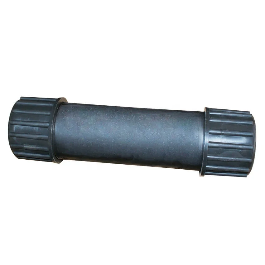
A pup joint is Casing, Pipe or Tubing shorter in length than a standard tubular string. This allows for the adjustment and installation of tools and various tubular components when placement downhole is critical for a specific project. A Spacer Pipe is another reference used to identify pup joints. Pup joint features consist of connections, lengths, weights and material grade.
Crossover pup joints are manufactured from seamless mechanical tube. As with all Crossover products, each piece is marked with a distinctive job number and heat number that is fully traceable. A complete range of sizes (1" to 4.5"), weights (standard or heavy wall), and grades (J-55, N-80, L-80, and P-110) are commonly available from stock in 2", 3", 4", 6", 10", and 12" lengths. Lengths up to 20" are available upon request.
Manufactured according to API Spec 5CT using prime API monogrammed, seamless oil country tubing. Optional diameters, lengths, weights, and grades are available upon request.
Seamless pup joints with premium connections are available in API and exotic alloy grades. Premium ends are threaded by the manufacturer or authorized licensee.
Available with standard or special perforation spacings. Each joint has four rows of ⅜ inch holes drilled longitudinally along the tube. Optional patterns, hole size, and lengths furnished upon request.
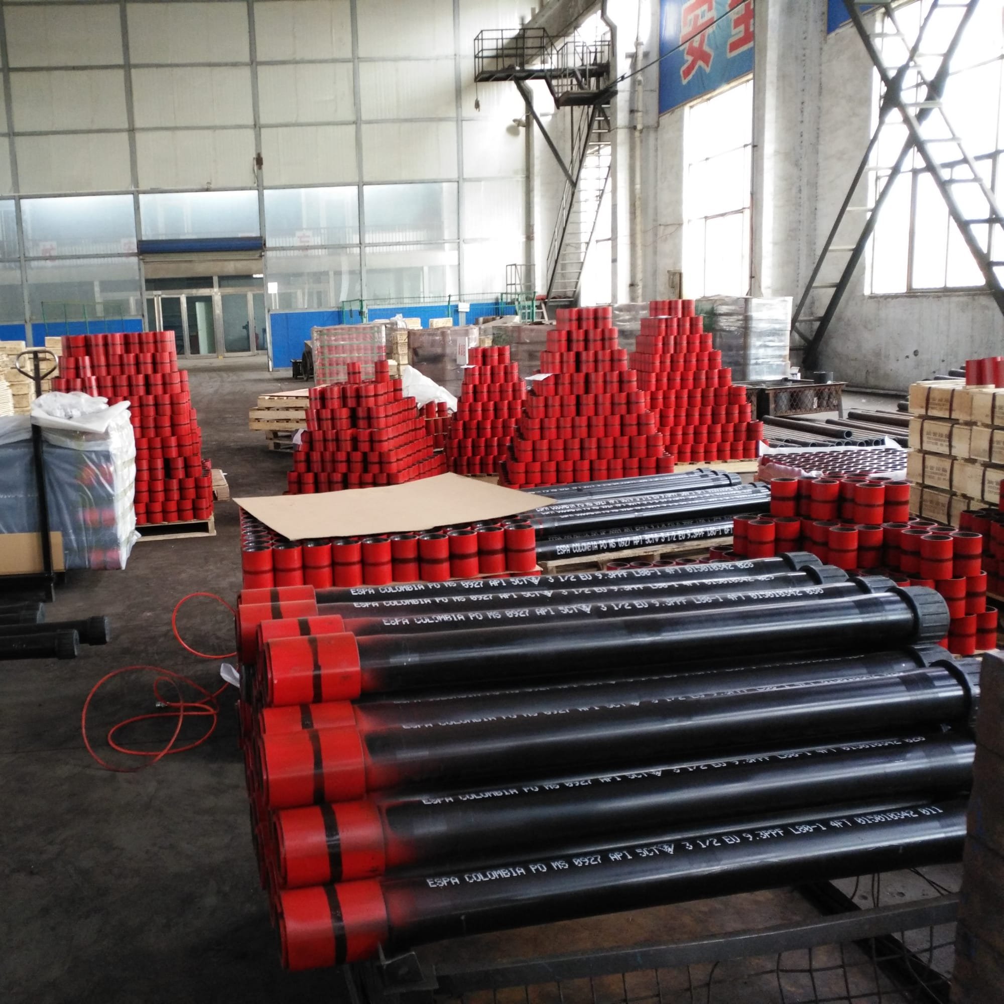
Crossover, Inc. handles many types of API Couplings. As a rule, we stock enough of your common couplings which enable us to ship the same day if needed. We carry in stock J-55, L-80, N-80, and P-110. As for sizes, we carry 2 3/8”, 2 7/8” 3 ½”, 4 ½” tubing and some of the casing sizes up to 13 3/8”. Stock connections are EU 8 Rd., Nu 10 Rd., LTC, STC, and BTC. Our couplings are primarily of USA manufacture. If origin is not important, we can source other origins and sometimes beat the USA manufactured cost.
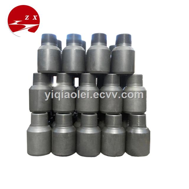
We manufacture a wide range of Crossover Couplings. Couplings are used to connect two sizes of pipes, or two different dissimilar threaded parts together. We offer special clearance couplings, special clearance couplings with bevels on both ends, and couplings with the API Seal Ring Modification.
Swages are generally Box x Pin with a transition on the outside diameter and the inside diameter of the swage to assure that there are no sharp corners to set up an area of stress risers. When stress risers occur, there is a chance that the part could fail due to the fact that the part would be prone to crack in these areas.
A blast joint is shorter in length than standard tubular joint. Built with a heavy wall pipe it is incorporated in the production string to facilitate production across any perforated interval and zone. Blast Joints are manufactured to the following specs connections, lengths, weights and material grade.
Crossover Blast Joints are heavy wall pin by box connectors used in tubing strings and are designed to minimize the effect of external erosive action caused by production fluids. Blast joints are located opposite the location of perforations in the production casing or just below the tubing hanger in sand frac designs. Crossover blast joints are manufactured from seamless mechanical tube in sizes ranging from 2 3/8” to 4 1/2” OD. Any length, grade of material, and threading is available at the customers request. Typical lengths are 10" and 20". Both API and Premium threads are available.
Crossover Flow Couplings are heavy wall box by box connectors used in tubing strings and are designed to minimize the effect of internal erosive action caused by production fluids. Flow couplings are located just above or below Landing Nipples, Safety Valves or Control Devices where turbulent flow problems are likely to occur. Crossover flow couplings are manufactured from seamless mechanical tube in sizes ranging from 2 3/8” to 4 1/2” OD. Any length, grade of material, and threading is available at the customers request. Typical lengths are 3" and 6". Both API and Premium threads are available.
Crossover Coarse Thread Tubing Safety Joint provides for emergency recovery of the major portion of the tubing string should it become necessary to abandon the equipment below. Precision left-hand threads facilitate the release of the joint by right-hand tubing rotation. Equipment requiring right-hand rotation should not be used below the Safety joint.
Crossover Straight-Pull/Shear-Out Safety Joint is used between packers in dual and triple completions and in selective completions using Hydrostatic Single-String Packers. It is also used when rotational releasing is not desired. When ran above the upper packer in a single-string completion, however, the shear value should be adjusted to compensate for any hydraulic conditions that exist when the string is landed, or that are created by well treating operations. They are available in keyed and non-keyed configurations.
Crossover Gas Anchor is an effective and simple design. It will increase oil and gas production, improve efficiency of the lift system, correct artificial lift problems caused by incomplete pump fillage due to gas interference and reduce operating cost.
Crossover can build these in any of the regular API Grades such as J-55, L-80, or P-110. These are usually only made going up or down one size in either direction such as ¾” to 1” or 1 ½” to 2”.
A saver sub falls under the drill string accessory tool category and a short pipe that is replaceable and expendable without a major investment. This accessory protects the Kelly or topdrive component threads and those components represent a significant capital cost and considerable downtime when replaced. Saver sub are manufactured to the following specs connections, lengths, weights and material grade.
A lift sub falls under the drill string accessory tool category and utilized to mobilize various tools during drilling or fishing operations. Lift Sub are manufactured to the following specs connections, lengths, weights and material grade.
A circulating sub falls under the downhole accessory tool category that regulates flow rates, especially drilling in slimhole wells or wellbore cleanout projects. Circulating sub is manufactured to the following specs connections, lengths, weights and material grade.
Crossover Drop Ball Circulating Subs are manufactured from AISI 4140/4145. The standard is pin by box. They are activated by dropping a chrome steel ball, which lands on a sleeve and as pressure increases, the pins in the sleeve are sheared. This causes the sleeve to move down and expose four ports in the side of the sub diverting the fluid flow.
A side-entry sub falls under the drilling tool accessory category to allow various drilling, fishing, wireline operations through drill pipe without interference from the rig"s top drive unit. Circulating sub is manufactured to the following specs connections, lengths, weights and material grade.
The style shown is built from one piece of 4145M bar stock and the excess material milled away and then threaded. There are also Lift Caps which are Cast Steel Castings and are threaded with the correct thread, but the rest of the plug is casts to create the bail.
Some customers request Lift Caps with Pad Eye for lifting. These are also made out 4145M and can be manufactured to fit any of several shackles. They can be built with either the pin or the box facing down.
These brushes are generally run on Rotary Shoulder Drill String to Brush the inside of Casing Down Hole. These brushes will remove rust, scale and other contaminates that build up on the inside diameter (ID) of the casing. Usually run in preparation of running a packer or some other piece of equipment that needs a fairly uniform ID to set.
Crossover Inside BOP Valves are manufactured from AISI 4145. Crossover"s one piece design is much more robust than the traditional two piece construction design. Crossover"s one piece design typically allows for standard connection OD"s and shorter overall length parts. This eliminates the service break which allows for quicker disassembly.
A washover pipe is Casing or Pipe shorter in length than a standard tubular string. Made of large-diameter pipe with a cutting surface at the tip, washover pipe is run in the well and then the cutting edge grinds the fish to a smooth surface and continues normal operations. Washover Pipe is manufactured to the following specs connections, lengths, weights and material grade.
Crossover rotary shoes are manufactured from specially tempered steel to provide the ultimate in toughness and durability. They are used to cut a clearance between the fish and the wall of the well bore. Each shoe is tailored to fit a particular downhole need and normally is run on the bottom of one or more joints of washover pipe. Shoe design is dictated by whether it cuts on the bottom, on the OD, on the ID, or any combination of these. When hole sizes permit, additional clearances can be cut using side ribs, thus providing greater circulation.
Pipe system involves various components, including pup joint nipple and are made from different materials. We offer wholesale pup joint nipple to create a smooth channel for the pipe systems in both commercial and residential areas.
The materials used depend on the type of fluids it will convey. One of the more commonly used types is PVC fittings. Features of the PVC pipe fittings that make an appropriate is the allowance for a smoother wall surface which decreases resistance to the flow. It is also lightweight and cost-effective.
On the other hand, copper fittings are corrosion-resistant. As such, they have a higher tolerance to external factors. That makes copper pipe fittings a good option to adopt for underground plumbing.
Apart from materials, there are also other components of the pipe fittings to note. P-traps prevent odor by retaining a small pool of water to stop sewer gases from entering the bathroom. Pipe caps cover the end of pipes to stop the fluid flow and protect pipe threads.
The usage of the pipes plays a crucial role in the materials suitable. For manufacturing, pipes will need to be able to withstand the fluids conveyed. We provide solutions from pipe bends to copper pipe compression fittings for any piping system required.
Pup Joint Inc. is a machine shop that sells down hole tubular and casing accessories and equipment. We are a leading supplier of pup joints & accessories with API5CT & premium threads at very competitive prices. Our machine shop is a threading facility for all your threading & precision machining needs. PJI commenced operations in Houma, LA in July of 1997. Our staff has over 65 years of combined experience supplying quality products & services to the oil & gas industry.

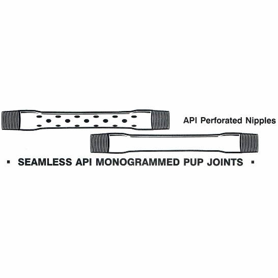
Perforated Production Tubes are joints of tubing with machined holes along four lines 90o apart along the length of the tube. Perforated Production Tubes are usually installed between the bottom two nipples of a completion. With this tool, downhole recording devices, such as temperature and pressure gauges, can be installed in the lower nipple profile to acquire flowing pressure and temperature measurements. The upper nipple provides a point to plug the tubing below a packer. This facilitates packer setting or workover operations. The Perforated Production Tube, sometimes called a Ported or Perforated Pup Joint, allows for unrestricted flow of fluid or gas. The use of this tool enhances the accuracy and reliability of acquired downhole production data, which otherwise would be distorted due to flow restrictions. The Perforated Production Tube comes standard with 200% flow area of the production string it is connected to.
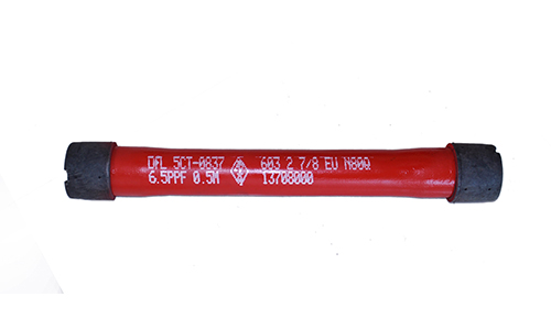
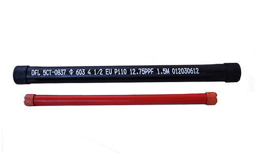
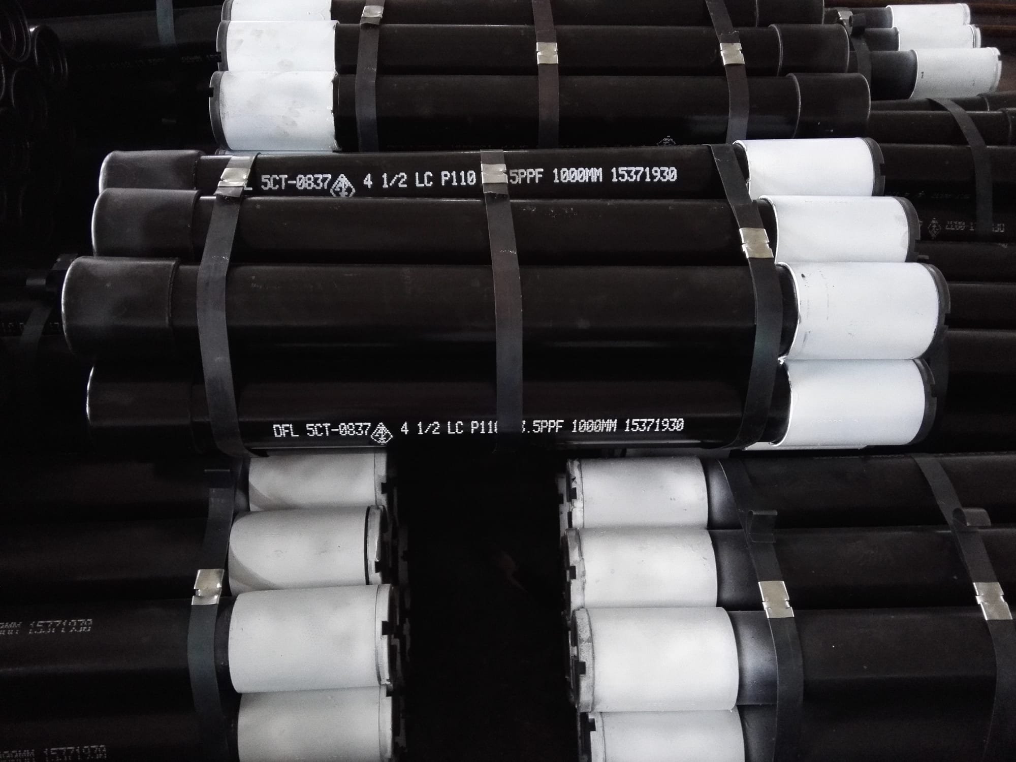
These J55, L80, N80Q & P110 pup joints are manufactured from seamless Grade J-55, L80 N80Q and P110 mechanical tubing. The API 5CT tubing pup joint is mainly used to adjust the height of the tubing strings. It is also used to adjust the depth of down-hole tools.

Casing pup joint is mainly used to adjust the height of the casing strings. It is also used to adjust the depth of down-hole tools. Our pup joints are manufactured in accordance with the API Spec5CT specification. The steel grades of the products of this kind are J55, K55, N80 and L80 P110. These products feature high corrosion resistance and long running life. As a pup joints supplier, we also produce the API 5CT tubing pup joint which is the fitting of the tubing strings. And we promise that all our ...
It is produced according to API 5CT Specification. Our precision-engineered pup Joints are ideal for spacing out down-hole assemblies and handling the production of tubing accessories. As a tubing pup joints manufacturer in China, we also provide API 5CT casing pup joint which is the accessory of the casing strings ...
Pup joint is a common fitting used in industry pipeline connection. It is a section of pipe of non-standard length used for making up a string of tubular to an exact total length. This product is a one-piece construction made from alloy steel. It features wing union end connections which eliminate the need for welds and threads. This pipe fitting is capable of bearing diverse fluids and working pressures. Our products in this category include tubing pup joints and the ones for casing pipe.
3.This product has undergone phosphating and copper coating treatment. It has superior anti-abrasion properties and its thread has good anti-adhesion performance.
1.Pup joint is mainly used to correct the overall length of a drill string to land at a specific depth while staying within the working area of the valve.
2.This pipe fitting is used to achieve precise depth readings in a well for various purposes, such as setting valves, nipples, packers circulating sleeves, etc.
As a pup joints supplier in China, Hebei Xinlian (Beijing) Petroleum Pipe Co., Ltd. possesses an advanced process line of pipes for petroleum which consists of first-rate CNC thread cutting machine, automatic screw machine, hydraulic press, jet printing equipment, etc. Our products have been exported to many countries, such as Germany, Japan, Rumania, Czech, Italy, UK, Austria, Switzerland, the US, Argentina and Singapore.
If a polished bore receptacle completion is desired then there is no need for a tailpipe unless it is considered necessary to have a means of obtaining pressure isolation beneath the polished bore receptacle in the event of a workover or to allow retrievable downhole pressure and temperature gauges to be installed.
The height of the tailpipe above the perforated interval depends upon whether it is intended to run wireline surveys across the perforated interval. If downhole surveys are required the base of the tailpipe should be set 150 ft above the top perforations or alternatively 30 ft if no surveys are intended.
Normally if wireline work is envisaged a wireline entry guide (WEG) is installed at the base of the tailpipe. If a landing nipple for gauges is to be installed then a 30 ft pump joint is located above the WEG and above this the landing nipple and the perforated flow tube to allow fluid entry into the production string.
If required the nipple will be installed above the perforated joint. If a selective nipple system is used and the well depth exceeds 7000 ft, a 30 ft pup joint would be located beneath this nipple. In addition, if a permanent packer is installed, a millout extension would be fitted. Finally if a locator seal assembly is to be used and an extended length seal bore is required, the sealbore extension would be fitted above the millout extension, beneath the packer.
Packer plug, pump-out and push-out plugs are used to temporarily isolate the tubing. Both the pump-out and push-out plugs are run with the packer, while the packer plug can be set when the packer has been previously set and retrieved with a work string.
The most commonly used circulation devices are the ported nipple, SPM and SSD. Difficulties experienced with well deviations and seal failure has led in considered cases to their elimination from completion strings, with dependence being placed on tubing punching or coiled tubing.
The majority of wells will include at least one landing nipple in the completion string. This is usually a "no-go" nipple at the bottom of the well conduit (string), where it may be used for:
Landing nipples may incorporate ports to provide tubing/annulus communication. Flow through the ports is governed by wireline run tools (separation sleeves, side door chokes), which are landed and locked in the nipple profile.
Slip, packer and collar type lock mandrels may be used where no landing nipples are available, however, the permissible differential pressure needs to be carefully analysed.
The basic choice between nipple systems is whether a no-go or selective nipple design is chosen. If a no-go nipple system is used then its use is checked by reference to a production performance optimisation package to calculate the effect on pressure loss of the reduced bore of the no-go shoulder. If it represents a major restriction to flow, the installation of flow couplings around the nipple is recommended. The bore of the nipple selected must be smaller than the smallest nipple bore used higher up the string, e.g. there must be sequential nipple bore reduction.
If a selective nipple is considered, then it will offer the capability to set the nipple size equal to the minimum nipple bore used higher up the string. The major problems identified with selective nipples are:
In deep wells, e.g. greater than 7000 ft, cable stretch may pose a problem in identifying exact nipple locations. For such cases, a minimum nipple spacing of 30 ft is recommended.
landing nipple requirements for flowing surveys vs. packer/collar/slip mandrels (Production Operations Well Services Guide, Well intervention activities - Document 2: Wireline operations);
SPMs are fitted in the well conduit where it is necessary to install a valve that will provide communication between the tubing and the annulus. The valves may be installed/retrieved by wireline or coiled tubing techniques.
A V-shaped locator with a grooved extension provides for continued orientation while moving the kick-over tool with side-pocket equipment. Equipment entry into the side-pocket before the orienting finger leaves the groove provides optimum installation conditions.
Sliding sleeves (also referred to as Sliding Side Doors, SSDs) are part of the tubing string and provide communication between the well production conduit and various annulus Various applications include: fluid displacement; selective testing, treating or producing multiple zones; commingled production; well killing (by fluid circulation); kicking off wells (gas lift); pressure equalisation; ·chemical injection.
Jar up to open sleeves, as opposed to jar down to open, have the advantage that a greater force can usually be exerted by upward jarring especially using hydraulic or spring jars. Downward jarring force, especially in deviated wells, is somewhat limited. Where a large differential pressure, annulus to tubing, is expected, down to open sleeves may be preferable, which place the tool below the communication port preventing tools being blown up the tubing.
Most sliding sleeves incorporate landing profiles, enabling a selection of control devices, including straddle tools to isolate a leaking sleeve, to be locked in.
The sliding side door is preferable to a ported nipple or a SPM if high circulation rates are required, e.g. well killing. However, the SSD should not be considered for use without careful analysis when:
Do not install sliding sleeves opposite perforations unless it is unavoidable. Ensure there is at least 6 ft between blast joints and sliding sleeves.
There are usually wireline run/retrieved calibrated orifices to restrict fluid flow in the tubing. During the design stage appropriate landing nipples have to be selected and located for the installation of chokes and regulators to:
These can be of two types; one that is manually adjusted to help in spacing out, usually below packers in dual or triple completions, and one that allows limited tubing movement to facilitate making-up below multiple string packers and to allow for setting tandem hydrostatic packers.
These are used between packers in dual and triple completions and in selective completions using hydrostatic single-string packers. The shear pin safety joint is a device that enables stuck tubing to be sheared off, but because it introduces a weak point, its use should be restricted wherever possible.
Tubing cutters can be used to cut the tubing at any desired depth in most wells, but where sand production is a problem, possibly preventing the cutter reaching the desired depth, a safety joint could be considered.
These are important aspects of life-of-the-well completion planning. They are designed to inhibit the effects of corrosion/erosion caused by flow turbulence and jetting actions.
Blast joints are used in the tubing string opposite the perforations in producing zones where the jetting action of fluid can erode the outside of the tubing.
Flow couplings should be considered in high rate gas wells above and below completion accessories which restrict the tubing or induce turbulence, such as SSSVs and side pocket mandrels (SPMs).
They are used to centralise blast joints in the casing, particularly in deviated wells. They should be installed at least every 40 ft (12 m) (or part of 40 ft) of the blast joints.
Tubing shoes (or "mule" shoes) are short, cut-away lengths of tubing fitted to the bottom end of a tubing string to facilitate stabbing into a packer or packers. The outside should be barrel shaped to aid entry into the packer bore and to prevent hold-ups when running, and the inside bottom edge should be chamfered to aid wireline re-entry. When the tubing string is stepped down in diameter below the packer, some form of centraliser(s) should be fitted to, or near the shoe, especially in deviated wells.
This tool is designed specifically to eliminate or reduce paraffin (wax) and scale. The magnetic flux created by the tool, located within the well conduit near the reservoir, conditions the produced fluids such that scale and wax do not form within the tubing.
A number of manufacturers/supplies can now offer PDG systems. The systems vary depending on the application (e.g. fibre optic system, retrievable sensors, etc.) and overall requirements (e.g. reservoir management, ESP control, flow control, etc.). Reliability of PDG systems is a concern (75% probability of surviving for five years after installation, most failure occuring immediately after installation).
The distance between the closest perforations of adjacent zones should preferably be more than 30 ft, to allow for packer, packer accessories and blast joint positioning.
Experienced and competent wireline operators should be capable of locating a landing nipple within 0.1 to 0.2% of its actual depth. The minimum recommended distance between landing nipples, therefore is:
7" tubing, utilised to minimise pressure drop, reduces the number of wells required and defers compression. Low fluid velocities minimise potential erosion/corrosion problems at high flow rates.
The lower sliding sleeve provides an alternative flow path if the plug becomes stuck in the "R" nipple. The upper sliding sleeve gives a large port area for routine well killing. It is positioned above the chemical injection side-pocket mandrel to avoid corrosion and inhibitor deposits in the annulus.
The packer is set in 95/8" casing as it backs-up liner lap. A contingency completion with the addition of a 7" "SAB" packer and anchor latch permits the liner lap to be straddled.
The tubing collapse resistance exceeds the worst design case by factor of 1.1 (tubing pressure zero, annulus liquid filled, plus maximum surface casing head pressure).
Note that this design could be challenged, for example, why not a monobore completion, why not 13 Cr tubulars to surface, what type of VAM connection, etc.

Pup Joint Inc. is a machine shop that sells down hole tubular and casing accessories and equipment. We are a leading supplier of pup joints & accessories with API5CT & premium threads at very competitive prices. Our machine shop is a threading facility for all your threading & precision machining needs. PJI commenced operations in Houma, LA in July of 1997. Our staff has over 65 years of combined experience supplying quality products & services to the oil & gas industry.
Pipe system involves various components, including 3 8 nipple pipe and are made from different materials. We offer wholesale 3 8 nipple pipe to create a smooth channel for the pipe systems in both commercial and residential areas.
The materials used depend on the type of fluids it will convey. One of the more commonly used types is PVC fittings. Features of the PVC pipe fittings that make an appropriate is the allowance for a smoother wall surface which decreases resistance to the flow. It is also lightweight and cost-effective.
On the other hand, copper fittings are corrosion-resistant. As such, they have a higher tolerance to external factors. That makes copper pipe fittings a good option to adopt for underground plumbing.
Apart from materials, there are also other components of the pipe fittings to note. P-traps prevent odor by retaining a small pool of water to stop sewer gases from entering the bathroom. Pipe caps cover the end of pipes to stop the fluid flow and protect pipe threads.
The usage of the pipes plays a crucial role in the materials suitable. For manufacturing, pipes will need to be able to withstand the fluids conveyed. We provide solutions from pipe bends to copper pipe compression fittings for any piping system required.
Drilling templates are old and well known but none have in the past been equipped with wellhead connectors carried by the template which can be moved between the template and the wellhead during completion or workover operations. Further, there has not been known a casing head provided with means for supporting a wellhead connector which is movable between the support means and tubing head.
Wellhead connectors are known, but are connected between flow lines and the casing head and are very large and heavy. As the connectors are secured to the casing head, the tubing hangers of these types of wellheads are protected from outside forces such as those imposed by fishing nets snagging a wellhead.
Known wellhead connectors are complex in their latch and release mechanisms. They are not generally capable of being handled by remote operated vehicles and do not include a simple latch and release mechanism provided by a reciprocal sleeve together with provisions for locking the connector in release position by a system which is released by reciprocation of the control sleeve thus preventing accidental movement of the connector system to latch position during handling.
An object of this invention is to provide a subsea wellhead in which a locked down tubing hanger may tilt relative to its landing nipple while maintaining a seal therewith.
Another object is to provide a wellhead connector which is latched and released by reciprocation of a control sleeve in which the connector is held in the unlatched position by a releasable lock which is also controlled by the control sleeve.
Another object is to provide a subsea drilling template for drilling a plurality of wells in which wellhead connectors are carried by the template on dummy posts and are movable between the dummy posts and associated wellheads.
Another object is to provide a subsea wellhead having a guide frame and a dummy post on the guide frame and a wellhead connector movable between the wellhead and the dummy post.
Another object is to support a wellhead connector on a tubing hanger, thus reducing the size and weight of the connector which permits handling of the connector by a remote operated vehicle.
FIG. 5A and its continuation view FIG. 5B are sectional views taken along lines 5A--5A and 5B--5B of FIG. 4 with a fragment of the landing nipple shown in dashed lines;
Referring first to FIG. 1, a drilling template is indicated generally at 10. The template includes a grid of structural members which in the illustrated embodiment comprises spaced pipes 11 and 12 secured to each other by connecting pipes 13, 14, and 15. While the grid is shown to be rectangular in form, it will be appreciated that the shape of the grid is not critical and may take any desired form. While the grid may be made up of large pipes welded together as illustrated, any other type of structural members may be utilized. The grid illustrated is composed of two identical sections each providing for the drilling of three wells through the template. As these two sections are identical, only one will be described here.
A structural member such as an I-beam or angle iron 16 is secured to the pipe 11 and extends between pipes 13 and 14. Another structural member such as an I-beam or angle iron 17 is spaced from the member 16 and extends between the pipes 13 and 14. Additional structural members 18, 19, 21, and 22 extend between pipes 11 and structural member 17 to define therewith open spaces 23, 24, and 25 in the grid through which wells may be drilled.
These dummy posts are adapted to support the wellhead connectors indicated generally at 29. These wellhead connectors (which will be disclosed in detail hereinafter) are shown in solid lines on the wellheads after the wells have been completed. One wellhead connector is shown in dashed lines on dummy post 26 illustrating that the wellhead connector is movable between the dummy posts and the wellhead for completion of the well and for workover operations.
The template includes a plurality of production pipes, one of which is shown at 31. The production pipe 31 receives production fluid from the flexible hose 32 connecting the production pipe with the wellhead connector 29 associated with dummy post 26. Other production pipes not shown are connected to flexible hoses 33 and 34 extending to other wellhead connectors 29. In like manner, annulus hose connections 35, 36, and 37 extend from the wellhead connectors 29 to a pipe located adjacent the production pipe 31, but not shown. In further like manner, control lines indicated at 38, 39, and 41 are also of a flexible nature and extend from the wellhead connectors to control lines secured to the grid and not shown.
The grid supports a marine riser indicated generally at 42. Within the riser a plurality of flow lines 43 connect the template to the surface and provide for fluid flow between the surface and the several wells. Also within the riser are the control conduits 44 which connect to the control lines such as 38, 39, and 41 for controlling equipment such as subsurface safety valves which will be positioned in the tubing below the mud line.
One of the dummy posts is shown in FIG. 2. The post is a tubular member 45 having a closure 46 at its lower end with the upper end of the tubular member 45 being open. On the upper outer periphery of the post there is provided a grooved configuration 47 adapted to cooperate with latch lugs in the wellhead connectors to permit latching of the wellhead connectors to the post. The upper outer periphery of the post is provided with a seal 48 to seal between the post and a downwardly facing surface in the wellhead connector.
A check valve indicated generally at 49 provides for flow from the interior of the post to the exterior of the post while preventing backflow. With a wellhead connector positioned on the post and sealingly secured thereto, protective fluids may be pumped through the flexible hoses into the wellhead connectors and the interior of the dummy post to fill the interior of the connector and the interior of the dummy post and protect the wellhead connector from the elements. Preferably the check valves 49 are back pressure valves capable of holding the protecting fluids within the wellhead connector and the post but permitting fluids to be pumped into the system and, if desired, exhausted through the back pressure valve.
A wellhead constructed in accordance with this invention is shown in FIG. 3. The wellhead includes an outer casing 51. A guide frame 52 is carried by the outer casing 51 and includes a plurality of guide posts, one of which is shown at 53. The guide frame 52 also supports the dummy post 54 for supporting the wellhead connector indicated generally at 55 during drilling or completion of the well or during workover as desired.
An intermediate casing 56 is supported within the outer casing 51 and in turn supports the inner casing indicated generally at 57. This inner casing 57 includes the special no-go nipple 58 for supporting the tubing hanger indicated generally at 59. As will be explained hereinafter in more detail, the seal means indicated generally at 61 and the hold-down means indicated generally at 62, permit the tubing hanger 59 to tilt within the casing 57 without breaking the seal 61. This prevents a loss of sealing function in the event the tubing head is tilted by a fishing net or the like engaging the wellhead connector 55 and exerting a horizontal force on the wellhead connector.
The tubing hanger includes a nipple indicated generally at 60 having grooves at its upper end for receiving the latch lugs of the wellhead connector as will more fully appear hereinafter.
The wellhead connector 55 includes an outer depending bell-shaped member indicated generally at 63 which telescopes over the intermediate casing 56 and wiper means indicated generally at 64 carried by the bell-shaped member 63. The wiper means engages the intermediate casing 56 and prevents marine life and other undesirable matter from moving upwardly into the wellhead connector.
The wellhead connector may include the diverter housing indicated generally at 65 providing for vertical access into the well and diverted flow from the well through the flexible hose 66 to a flow line sled and flow lines (not shown). A similar second flow line is located immediately behind the flow line 66. The flexible hose 67 is the annulus line and provides for access to the well annulus as will more fully appear hereinafter. The wellhead is closed at its upper end by the vertical access cap 68.
The tubing hanger body includes the lower body sub 74 and the upper body sub 75. The upper body sub 75 has at its upper end a pair of adjacent grooves 76 and 77 for latching of the wellhead connector to the tubing head as shown in FIG. 3. Projecting from the upper sub 75 is an orientation lug 78.
The lower end of the lower sub 74 is provided with a downwardly facing bevelled shoulder 79 which joins a lower surface 81 of constant diameter. These two surfaces cooperate with the seal indicated generally at 61 to seal between the seal 61 and the tubing hanger 59. The seal 61 provides a metallic seal between the landing nipple 57 and the tubing hanger 59. Preferably the metallic seal is provided by an upper metallic seal member 82 and a lower metallic seal member 83. It is further preferred that a resilient seal 84 be positioned between the two metallic seals 82 and 83. These three seals engage the upwardly facing no-go shoulder shown in dashed lines at 85 of the segment of landing nipple 57 shown in dashed lines in FIG. 5B.
The three seals 82, 83, and 84 are retained on the landing nipple by the lowermost seal indicated generally at 86 and the nut 87 on the lower end of the tubing hanger 57. This lower seal 86 provides a resilient seal with the bore of the landing nipple 57 at 88.
In accordance with this invention, the outer peripheral surface 88 on upper seal 82 and 89 on lower seal 83 form a frusto-conical surface. The no-go shoulder 85 on the nipple 57 forms a complimentary frusto-conical surface. The frusto-conical surfaces 85 and 88-89 extend tangent to a circle having its center at 91. As these surfaces are substantially segments of a sphere, they permit the tubing hanger to rotate or tilt about the point 91 if a horizontal force is applied to the upper end of the tubing hanger. Slight movement or distortion of the two metal seal rings may occur during this tilting movement.
The lower seal 83 is provided with an inner upwardly extending thin section 92 which is expanded by the downwardly facing shoulder 79 as the tubing hanger is supported in the landing nipple to place the resilient seal 84 in compression.
The hold-down means 62 includes the downwardly facing no-go shoulder shown in dashed lines at 93, the pair of expandable split rings 94 and 95 as well as means for expanding these rings. Two rings are preferred over one to provide large shoulder contact between the rings and the landing nipple as well as the tubing hanger.
The downwardly facing shoulder 93 in the landing nipple as well as the upwardly facing shoulder 96 on the upper ring are formed on lines tangent to a circle about the center 91. As these surfaces are again substantially segments of a sphere, they will move relative to each other and permit rotation or tilting of the tubing hanger about the center 91 when a horizontal force is applied to the tubing hanger as by the wellhead connector being snagged by a fishing net or the like. There will be a clearance between the casing head and tubing hanger above the hold-down rings and the tubing hanger will be able to tilt within this clearance until it engages the casing hanger without breaking the seal provided by the metal seal rings.
The tubing hanger has an upwardly and outwardly bevelled face 97 on which the lower ring 95 rests. The lower end of the lower ring 95 is bevelled complimentary to the surface 97. Also, the upper surface 98 of the lower ring and the lower surface 99 of the upper ring are complimentary and are bevelled slightly in an upward and outward direction. Thus, after the tubing hanger has been seated on the no-go shoulder 85, expansion of the rings 94 and 95 will affect relative upward movement of these rings to bring the upper ring 94 into firm engagement with the downwardly facing no-go shoulder 93 to hold the tubing hanger firmly on the no-go shoulder 85.
The expander includes the upper expander sleeve 101 and the lower expander sleeve 102. At its lower end the lower expander sleeve 102 is provided with a plurality of split expander fingers 103 which have upwardly and outwardly inclined surfaces 104 to provide a downwardly facing expander cone which when the sleeve 102 moves downwardly will project under the two rings 94 and 95 and expand them outwardly until the upper ring 94 firmly engages the downwardly facing no-go shoulder 93.
At the upper end of the upper sleeve 101, windows 106 are provided in the sleeve and within these windows are positioned slips 107 urged downwardly by springs 108 into engagement with cone segments 109. The slips 107 are provided with slip teeth which engage the upper tubing hanger section 75 and prevent upward movement of the expander sleeve 101-102. Thus, a setting tool engaging the setting sleeve 111 may move the setting sleeve and with it the expander cone 104 downwardly to expand the two rings 94 and 95. The slips 107 hold the expanders in their down position. When it is desired to release the tubing hanger hold-down rings, a tool engages the groove 112 in the setting sleeve 111 and an upward pull shears the shear ring 113 and the sleeve 111 moves upwardly until the inner enlarged diameter section 114 overlies the cone 109 and permits the cone, which is split segments, to expand outwardly and release the slips 107.
The tubing hanger includes the two upper pup joints 115 and 116 which have at their upper end resilient seals indicated generally at 117 and 118 and metal seal surfaces 117A and 118A for engagement by depending tubes carried by the wellhead connector 55.
The wellhead connector includes elongate mandrel means provided by the lower mandrel 121 and upper mandrel 122 secured together by the threaded connection 123. At the upper end of the upper mandrel are a pair of external grooves and orientation key indicated generally at 124 for suspending and manipulating the wellhead connector and for attaching the vertical access cap 68 (see FIG. 3).
A latch sleeve is provided by the lower latch sleeve 125 and the upper latch sleeve 126. These sleeves are held in spaced relationship by a plurality of spacer sleeves 127 extending between a flange 128 on the lower sleeve 125 and a flange 129 on the upper sleeve 126. Bolts 131 having a cap 131A engage the counterbore 132 in flange 129 and are threaded to the lower flange 128 by the threaded engagement 133. If desired, other means might be utilized to secure the upper and lower sleeves to each other.
One of the mandrel and sleeve carries a latch bowl means and the other carries latch lugs which are movable radially by the bowl means to latch the connector to a tubular member with telescoping movement of the latch sleeve. Preferably the latch bowl 135 is carried by the sleeve 125 and a plurality of latch lugs 136 are cooperable with the upwardly and outwardly inclined bowl 135 to force the latch lugs 136 inwardly in a radial direction to latch the wellhead connector to the tubing hanger as shown in FIG. 3. The latch lugs 136 may take any form such as the fingers illustrated which are held in the groove 137 by the enlargement 138 on the upper end of each of the lugs 136. The wellhead connector is run with the latch sleeve 125 in a lower position which permits the latch lugs 136 to expand. The wellhead connector is set down on the tubing head until the downwardly facing surface 139 on lower mandrel 121 rests upon the tubing head as shown in FIG. 3. Thereafter upward movement of the latch sleeve 125 cams the latch lugs 136 inwardly to lock the connector to the tubing head. The pup joint 141 extends into and sealingly engages the packing in the upper end of the tubing head such as packing 117 or 118 and surfaces 117A or 118A. The pup joint 141 directs flow to the flowway 142 in the wellhead connector.
A lug 144 carried by the lower sleeve 125 cooperates with a male slot 145 in the lower mandrel to maintain proper orientation between these parts. A ramp 146 carried by the lower sleeve 125 cooperates with the lug 78 on the tubing hanger to orient the wellhead connector with the tubing hanger where dual flow lines such as the flow line 140 and 141 are employed (see FIG. 6).
Control fluid may be delivered through the wellhead connector by way of the depending pup joint 147 which sealingly engages a flow line in the tubing hanger as shown in FIG. 3.
A releasable locking means indicated generally at 148 cooperates with a slip bowl and slips indicated generally at 149 to govern the relative reciprocal motion between the upper mandrel 122 and the upper latch sleeve 126 which in turn control the position of the lower latch bowl 135 and the latch lugs 136. The releasable locking means 148 locks the mandrel and sleeve in a position where the lower latch bowl 135 is ineffective to move the latching lugs inwardly and thus maintains the wellhead connector in the non-engaging position in a positive manner while it is being run. A control sleeve means indicated generally at 151 is reciprocal on the upper latch sleeve 126 to control the setting and release of the slip means and the releasable locking means. Referring first to the first to the system 149, a slip bowl carrier is provided by a tubular extension 152 on the upper end of the upper latch sleeve 126. This extension 152 has a plurality of vertically extending slots 153 and at its upper end a plurality of circumferentially arranged windows 154 which support segmented ring segments 155, which have inner surfaces 156 which are upwardly and inwardly inclined to provide a slip bowl.
The segmented segments 155 cooperate with slips 157 which have downwardly facing teeth and engage the upper mandrel 122 to lock the upper mandrel and upper latch sleeve 126 in a position to lock the wellhead connector to the tubing hanger.
The slips 157 are carried by the milled spring 158 by engaging an inwardly projecting flange 158A on the mill spring 158. The mill spring is secured at its upper end to the control sleeve 159 by the pin 161.
The milled spring 158 has a counterbore 158B at its upper end into which the ring segments 155 may expand when the control sleeve 159 is moved downwardly to move the counterbore 158B behind the segmented rings 155 to release the slips 157. With the system such that the slips 157 are engaged by the segmented ring 155 the milled spring 158 is in tension urging the slips upwardly against the segmented ring 155.
At its lower end, the control sleeve 151 is provided with a detent flange 162 which detents the sleeve in its upper or lower position by moving over the resilient detent ring 163.
The releasable locking means 148 locks the wellhead connector in a relationship where the lower latch bowl 135 is ineffective to move the latch lugs inwardly. An external groove 164 cooperates with locking lugs 165 to releasably lock the upper mandrel 122 to the upper latch sleeve 126.
The locking lugs 165 are carried in windows 166 in the upper latch sleeve 126. The tubular extension 152 has a downwardly facing shoulder 152A and the control sleeve 151 has an upwardly facing shoulder 167 confronting the shoulder 152A. For convenience, this shoulder 167 as well as the detent flange 162 are carried on a threaded extension 159A of sleeve 159.
The milled spring 168 urges the lock lugs 165 inwardly into the groove 164 and when the lugs reside in groove 164 the milled spring expands and a groove 168A in the lower end of milled spring 168 overlies the lugs 165 to lock them in the groove 164 and secure the wellhead connector in the unlatched position.
Vertical access is provided through the wellhead connector tube 174 and another tube (not shown) which is carried in the upper end of the lower mandrel 121. Grooves 175 and 176 are provided in the bore through the tube 174 for receiving locking dogs. For a purpose which will appear hereinafter the upper surfaces 177 and 178 of the grooves are inclined downwardly and outwardly to provide cam surfaces. Below the grooves a smooth bore 179 is provided. Between the smooth bore and grooves, an upwardly facing no-go shoulder 181 is provided.
The wellhead plug includes lower housing 182 and upper housing 183 secured together by the threaded connection 184. The lower housing carries the orientation pawl 185 urged by spring 186 into the vertical slot 187 in the lower mandrel 121 to orient the plug so that the inclined face 188 on the lower end of housing 182 is aligned with and forms a part of the passageway 142 to divert TFL tools which may pass through the flow line of the wellhead connector.
The plug is provided with downwardly facing shoulder means 189 wh-ich confronts the no-go shoulder 181. A metal seal ring 191 seals between the no-go shoulder and the confronting downwardly facing shoulder. A metal filler ring 192 of generally triangular shape is positioned immediately below the seal ring 191 and provides a shoulder for the V-packing 193 which seals with the smooth bore 179. The two metal rings and the V-packing are positioned prior to assembly of the upper and lower body sections of the plug and after the threaded connection 184 is made up, the locking pin 194 together with the threaded connection 184, lock the upper and lower sections of the plug body in the desired relationship.
Above the downwardly facing shoulder 189 the upper body 183 has a plurality of windows 195 in which lugs 196 are carried. These lugs have a pair of external lands providing upwardly facing shoulders 197 and 198 which are complimentary to and engage the cam surfaces 177 and 178 in tube 174.
The lugs 196 are expanded by a downwardly facing cone 199 carried on stem 201. A wrench means provided by a crossbar 202 is provided at the upper end of the stem 201 and rotation of the stem by means of the crossbar moves the expander cone 199 downwardly by make-up of the thread system 184 in a blind bore 204 in the body 183 and on the lower end of the stem. Prior to make-up the cone may be held in an elevated non-engaging position by the shear pin 203.
Desirably the plug may be removed by a vertical pull and for this purpose release means for the cone is provided. The cone is a part of a sleeve 206 which carries dogs 207 for cooperation with groove 205. Props 208 pinned to the sleeve 206 by shear pins 209 hold the dogs in groove 205. The props 208 are collet-like fingers on the lower end of the release sleeve 211. The sleeve 211 has an internal groove 212 providing shoulder 213 which may be engaged by a pulling tool to raise the release sleeve 211, shearing pin 209 to remove the props 208 from around the dogs 207. When this occurs the dogs 207 may move outwardly releasing the expander cones from the stem thus releasing lugs 196 from the landing nipple tube 174 and releasing the plug for removal. Confronting shoulders 200 and 220 may be engaged by a pulling force if needed to release lugs 196.
In FIG. 9B, an alternate form of this invention is illustrated. The no-go shoulder of the landing nipple indicated generally at 57A is provided by an arcuate surface 85A which cooperates with a mating arcuate surface on the metal seal indicated generally at 61B. The hold-down shoulder 93A is also arcuate and cooperates with the arcuate surface 96A on the upper hold-down ring 94A. The radius lines 214, 215 and radius lines 216, and 217 of FIG. 9A illustrate that the no-go shoulder and the hold-down shoulder in both forms are struck about the single center 91. Thus, in FIG. 9B the no-go shoulder 85A and the hold-down shoulder 93A are segments of spheres of different diameter. The remainder of FIG. 9B is identical to FIGS. 5B and 9A.
In operation the wellhead of FIG. 3 is conventionally completed to include the landing nipple 57 in the innermost casing. If the template of FIG. 1 is to be used several wellhead connectors are carried on their dummy posts and the wells are drilled and completed through the windows in the template.
The tubing hanger 59 or 59A is run into the well and landed on the no-go shoulder 85 or 85A as the case may be, to support the tubing hanger. A setting tool engages the sleeve 111 and a downward force shears pin 105. Further downward force drives the expander cones 104 under the rings 94 and 95 until the expander cones and hold-down rings reach the positions shown in FIGS. 9A or 9B. At this time the slips 107 lock the expanders in the expanded position and hold the hold-down rings firmly in engagement with the hold-down shoulders. As there is clearance between the tubing hanger and its supporting landing nipple, a lateral force on the tubing hanger may induce movement of the tubing hanger about the point 91 with such movement being permitted by the arcuate or substantially arcuate no-go supporting surface and hold-down surface in the landing nipple in cooperation with the complimentary surfaces on the metal seal and hold-down ring.
When it is desired to remove the tubing hanger, a pulling tool engages in groove 112 and an upward force shears the shear wire 113 permitting upward movement to bring the groove 114 into overlying relationship with the expander cone segments 109 to permit their expansion and release of slips 107. Further upward force returns the expander cone 104 to the position shown in FIG. 5B to release the hold-down rings 94 and 95 and permit removal of the tubing hanger.
After the tubing hanger has been landed and locked in place, the wellhead connector is lifted from its dummy post and set down on the tubing hanger until the surface 139 in the lower mandrel of the wellhead connector is supported on the upper end of the tubing hanger. At this time the seal ring 218 forms a metal seal between the upper end of the tubing head and the lower end of the lower mandrel 121 of the wellhead connector. This seal permits testing of the stab seal during landing procedures and is a back-up seal for the stab seals.
While positioning the wellhead connector on the tubing hanger, the parts will be in their position shown in FIG. 8 with the dogs 165 locking the latch lugs 136 and latch bowl 135 in their non-engaging position with the latch lugs 136 expandable into the groove 219 in the lower latch sleeve 125.
With the wellhead connector supported on the tubing hanger, a suitable running tool (not shown) secured to groove 210 in the control sleeve 151 moves the control sleeve upwardly. During this movement the detent flange 162 passes over detent 163 and the control sleeve shoulder 167 engages the mill spring 168 placing it in compression and moving it from over the locking lugs 165 permitting these lugs to expand out of the groove 164 as shown in FIG. 7A. The shoulder 167 on the control sleeve engages the spacer sleeve 169 and further upward movement of the control sleeve transmits force through the shoulder 152A to the carrier 152 and thence to the upper latch sleeve 126. This sleeve may now move upwardly as the locking lugs 165 have been released. In such movement, force is transmitted to the lower latch sleeve 125 and the slip bowl 135 raised to engage and move the latch lugs 136 radially inwardly where they engage and lock into the grooves 76 and 77 (FIG. 5A) on the tubing hanger thus locking the wellhead connector to the tubing hanger.
As the control sleeve 151 is pulled upwardly, the milled spring 158 is placed in tension pulling the slips 157 upwardly under the segmented ring 155. As the upper end of the milled spring is secured to the control sleeve by pin 161, it has moved upwardly to the position shown in FIG. 7A. In this position, the cone provided by the ring segments 155 are moved out of the counterbore 158B and are held in their inward or retracted position by the upper internal surface of the milled spring 158 as shown in FIG. 7A. The ring segments urge the slips 157 into engagement with the upper mandrel 122 and latch the mandrel and the latch sleeve to each other in a position locking the wellhead connector to the tubing hanger as shown in FIGS. 3, 7A and 7B.
If it is desired to provide for vertical entry into the well, the access cap 68 is removed and a pulling tool run into the tube 174. Upward force on the release sleeve 211 shears pins 209 permitting removal of the prop fingers 208 from over the dogs 207 permitting them to expand out of groove 205. As the props 208 come into engagement with the surface 200 on the sleeve 206, they exert an upward force on the expander 199 to release the plug which now may be removed.
At the surface the well plug may be redressed and rerun with the stem 201 held in its upper position by the shear pin 205. A rotary jar (not shown) imparts rotational movement to the stem 201 through the wrench pin 202 to shear the pin 205 and drive the stem downwardly through the action of the thread system 203 to where the lugs 196 are expanded into engagement with the dog body and the upper cam surfaces on lugs 196 force the plug downwardly to compress the metallic seal 191 and hold this seal in compressed condition to provide a metallic seal in cooperation with the resilient seal provided by the V-packing 179.
When it is desired to remove the wellhead connector, a pulling tool engages the upper end of the control sleeve 151 and downward force is exerted to drive this sleeve downwardly until the detent flange 162 moves over the detent 163. When this occurs, the lugs 155 may move into the counterbore 158B on the milled spring to release the slips 157. With these slips released, further downward force on the control sleeve is transmitted through the lower end of the control sleeve to the flange 129 to move the latch sleeve downwardly relative to the mandrel and disengage the latch bowl 135 from the latch lugs 136 thus releasing the wellhead connector from the tubing hanger. As the upper latch sleeve 126 moves downwardly, the locking lugs 165 will drop into grooves 164 and the mill spring 168 will extend such that its lower section overlies the locking lug to lock the wellhead connector in the disengaged position as shown in FIG. 8. At this time the wellhead connector may be picked up and set over on its associated dummy post.
Norsk Hydro operates the Snorre Field in the Norwegian sector of the North Sea with a tension leg platform (TLP) and a sub-sea production system. The initial sub-sea wells were designed with completions that would allow through-flow-line servicing, and while the wells were functioning as designed, production had been declining. Therefore, Norsk Hydro felt that the completion concepts should be evaluated for new field developments. The ensuing investigation and development project led to a novel well completion concept, which is the first "intelligent well" subsea completion installation offshore Norway.
This innovative design changes retain the original through-flow-line (TFL) service technique system and subsea infrastructure without any modifications, maximize production by introducing 7-in. tubing, and include hydraulically operated inflow control devices.
License approval for prototype development and qualification was given in the summer of 1999, and the system components were in-house tested at the supplier base in Dallas during the fall of 1999. A thorough system qualification was performed at an independent Norwegian drilling and well test center during spring/summer of 2000. The qualification included a full test-well installation and necessary intervention activities to prove the functionality of the concept. The system was qualified during the summer of 2000. The first subsea well installation was done at Snorre and put on production in December 2000. The well completion consisted of a 4-zone/interval design for improved reservoir management.
The development process and qualification of the system has been conducted in a very short time period from idea to offshore implementation. This is mainly the result of a very focused personnel team with competent and dedicated personnel between supplier, operator, and 3rd party testing contractor.
Our range of products include Blank Adapter SH-500-A, Box-Box Flow Coupling SH502-FC, Combination Adapter SH-500-A, Combination Flow Coupling SH502-FC, Coupled Pup Joint SH503-PJ and Open Hole Hydraulic Set Packer SH518-OHP.
SledgeHammer Adapter is a short tubular part with ‘Box-Pin’ thread configuration which is used to connect two tubular parts with same or different thread types and sizes. This also can be referred to as a “cross-over”.
Flow Couplings are heavy wall connectors used in tubing strings and are designed to minimize the effect of internal erosive action caused by production fluids. Flow couplings are located just above and below of flow control equipments where turbulent flow problems are likely to occur.
SledgeHammer Adapter is a short tubular part with ‘Box-Pin’ thread configuration which is used to connect two tubular parts with same or different thread types and sizes. This also can be referred to as a “cross-over”.
SledgeHammer Adapter is a short tubular part with ‘Box-Pin’ thread configuration which is used to connect two tubular parts with same or different thread types and sizes. This also can be referred to as a “cross-over”.
Suitable plugging devices include, but are not restricted to, a pump-out plug, KLC (Locking Ball Landing Collar) ball seat, horizontal ball seat, or a wireline blanking plug seated in the proper landing nipple.
his is a completion accessory that facilitates completion and gravel pack operations by providing pressure and fluid sealing at selected point in completion assembly.
SledgeHammer Adapter is a short tubular part with ‘Box-Pin’ thread configuration which is used to connect two tubular parts with same or different thread types and sizes. This also can be referred to as a “cross-over”.
The forces generated by thermal expansion or contraction can be significant. A device or completion component designed to enable relative movement between two fixed assemblies in the event of thermal expansion or contraction.
The “Wireline Entry guide” are used for safe re-entry of wireline tools from the casing into the tubing string. The internal bevel guides the wireline or slick line tool string back into the tubing.
The seals unit provide positive seal to higher pressures and temperatures. Many types of seals units are available, and others can be designed to fit specific needs. Molded seal units and Premium seals are the major seals units.


 8613371530291