
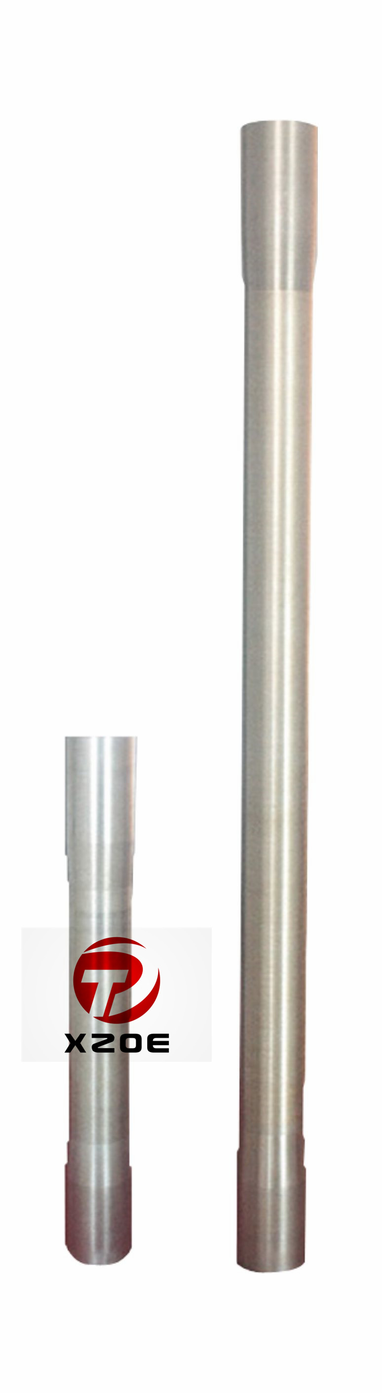
riser pup joint free sample

These J55, L80, N80Q & P110 pup joints are manufactured from seamless Grade J-55, L80 N80Q and P110 mechanical tubing. The API 5CT tubing pup joint is mainly used to adjust the height of the tubing strings. It is also used to adjust the depth of down-hole tools.

In offshore drilling operations in deep water, the operator will perform drilling operations through a drilling riser. The drilling riser extends between the subsea wellhead assembly at the seafloor and the drilling vessel. The drilling riser is made up of a number of individual joints or sections. These sections are secured to each other and run from a riser deploying floor. The drilling riser also normally has a number of auxiliary conduits that extend around the main central pipe. The auxiliary conduits supply hydraulic fluid pressure to the subsea blowout preventer and lower marine riser package. A recent type of drilling riser does not require auxiliary lines spaced around it. That type of drilling riser is built to withstand high pressure, and the blowout preventer is located on the drilling rig.
The central pipe of a drilling riser joint has a pin member on one end and a box member on the other end. The pin of one riser joint stabs into the box of the next riser joint. In one type of riser joint, flanges extend outward from the pin and box. The operator connects the flanges together with a number of bolts spaced around the circumference of the coupling. In another type of riser, individual segments or locking segments are spaced around the circumference of the box. A screw is connected to each locking segment. Rotating the screw causes the locking segment to advance into engagement with a profile formed on the end of a pin.
In these systems, a riser spider or support on a riser deploying floor moves between a retracted position into an engaged position to support previously made-up riser joints while the new riser joint is being stabbed into engagement with the string. Wave movement can cause the vessel to be moving upward and downward relative to the riser.
In both types of risers, workers use wrenches to make up the bolts or screws. Personnel employed to secure the screws or the bolts are exposed to a risk of injury. Also, making up the individual bolts is time consuming. Often when moving the drilling rig moving the drilling rig from one location to another, the riser has to be pulled and stored. In very deep water, pulling and rerunning the riser is very expensive. At least one automated system is shown in U.S. Pat. No. 6,330,918 for making up riser locking segment screws.
In this invention, each joint of riser pipe has a box on one end and a pin on an opposite end. The pin having an external grooved profile formed thereon. At least one locking element is carried by the box for movement from an unlocked position into a locked position in engagement with the profile of the pin of an adjacent riser joint. A ring in engagement with the locking element causes the locking element to move to the locked position in response to movement of the ring relative to the locking element.
FIG. 7 is a sectional view of the riser coupling and handling tool shown in FIG. 6, taken along the line 7-7 of FIG. 6, but showing the handling tool in a retracted position.
FIG. 8 is sectional view of the riser coupling and handling tool, taken along the line 8-8 of FIG. 7 and showing the handling tool in the retracted position.
Referring to FIG. 1, a drilling riser 11 is schematically shown extending from a floating platform 13 for drilling offshore wells. Riser 11 is supported in tension by tensioners 15 suspended from platform 13. Riser 11 is made up of a plurality of riser joints 17, each approximately 40-65 feet in length. Each riser joint 17 has a central tubular member 18 of a desired diameter. Typically, several auxiliary lines 19 are spaced around the exterior of central pipe 18 for supplying fluids to the subsea blowout preventer for various drilling and completion operations. Auxiliary lines 19 are considerably smaller in diameter than central pipe 18. If a surface blowout preventer is used, auxiliary lines 19 might be omitted.
Each riser joint 17 has an upper flange 20 adjacent its upper end and a lower flange 21 adjacent its lower end. Auxiliary lines 19 extend through and are supported by holes provided in each flange 20, 21. A lower marine riser package 23 is shown schematically at the lower end of riser 11. Lower marine riser package 23 includes a number of hydraulically actuated components, such as a blowout preventer, pipe rams, and a quick disconnect mechanism. Lower marine riser package 23 also has a hydraulic connector on its lower end that connects it to a subsea wellhead assembly 25.
According to FIGS. 4 and 5, each auxiliary line 19 has a lower end 47 that slides sealingly over an upper end 49 of the auxiliary line 19 of the next lower riser joint 17. Lower and upper ends 47, 49 could be reversed. Recesses 51 may be located on the exterior of cam ring 39 to avoid contact with auxiliary line ends 47, 49. As can be seen by comparing FIGS. 4 and 5, moving can ring 39 from the lower position in FIG. 4 to the upper position of FIG. 5 does not affect the engagement of auxiliary line lower and upper ends 47, 49.
A variety of different tools could be employed for moving cam ring 39 from the lower position to the upper position and vice versa. One such handling tool 53 is shown in FIGS. 6-9. Handling tool 53 is supported on a spider base plate 55, which is made up of two or more retractable plates that define a central circular opening 57, when in the inner position, through which riser joints 17 can pass.
A plurality of support braces 59 are mounted on spider 55 for radial sliding movement on spider base plate 55 relative to the axis of riser 11. Support braces 59 are spaced circumferentially around opening 57. Braces 59 are shown in an engaged position in FIG. 6 on the lower side of upper flange 20 for supporting the weight of the riser suspended below. Hydraulic cylinders 61 are shown in FIG. 7 for retracting each of the braces 59 to enable the riser to be lowered or raised. In the example shown, the cylinder portion of each hydraulic cylinder 61 is stationarily mounted to spider base plate 55 and its reciprocating rod is attached to an outer end of one of the braces 59. In the extended position, the inner end of each brace 59 is almost or may be in contact with central pipe 18. In the retracted position, the inner ends of braces 59 will be located radially outward of the perimeter of central opening 57.
Carriage 63 comprises a pair of spaced-apart vertical side plates that provide support for a vertically extending actuating piston 73. In this example, a movable cylinder 75 reciprocates relative to a fixed piston 73, but the reverse could be employed. Hydraulic fluid pressure will cause movable cylinder 75 to move between an upper and a lower position while piston 73 remains stationary. An engaging member or jaw 77 located on the inner side of each hydraulic cylinder 75 engages cam ring 39 to causes cam ring 39 to move upward and downward in unison with hydraulic cylinders 75. Jaw 77 is a channel member with upper and lower horizontal flanges that slide over the upper and lower sides of cam ring 39. The lower flange of jaw 77 will depress and release detent 43 (FIG. 3) from cam ring 39 when cam ring 39 is in the upper position to enable cam ring 39 to be pulled downward during break out of riser joints 17.
In operation, when making up riser 11 (FIG. 1) for lowering into the sea, the operator places spider base plate 55 in an inner position, defining central opening 57 for riser 11. The operator retracts braces 59 (FIG. 7) and jaws 77 (FIG. 8), and makes sure that cam ring 39 is in the lower position shown in FIG. 8. The operator then lowers a first riser joint 17 through opening 57 (FIG. 8) and connects it to lower marine riser package 23 (FIG. 1), which is normally stored below platform 13. The operator causes hydraulic cylinders 61 (FIG. 7) to move braces 59 inward, then lowers the first riser joint 17 until upper flange 20 is resting on braces 59, as shown in FIG. 8. The operator lowers a second riser joint 17 and lands it on the upper end of the first riser joint 17, as shown in FIG. 8.
The operator then applies pressure to hydraulic cylinders 69 to cause jaws 77 to engage cam ring 39, as shown in FIG. 9. The operator then supplies hydraulic pressure to actuating cylinders 75 to move cam ring 39 to the upper position shown in FIG. 6. When moving to the upper position, cam ring 39 will push locking segments 35 into locking engagement with profile 29. While doing so, the connection between the riser joints 17 will become preloaded. The operator then retracts hydraulic cylinders 69 to retract jaws 77 and moves actuating cylinders 75 back to a lower position. Once jaws 77 are released from cam ring 39, detents 43 (FIG. 3) will snap under cam ring 39 to make sure that it does not move downward.
When the operator is ready to install the next riser joint 17, he lifts the entire riser string from support braces 59, retracts braces 59 with hydraulic cylinders 61 (FIG. 7), and lowers riser 11 for the length of one riser joint 17 to repeat the cycle. The operator can break out the joints 17 of riser 11 by reversing the procedure.
FIGS. 10-17 illustrate a second embodiment. Riser joints 17 are constructed generally the same as in the first embodiment, except the coupling is inverted. The same numerals are employed for components that are substantially the same. During make up, box 31 is on the upper end of a riser joint 17 and faces upward. Pin 26 is on the lower end of the next riser joint 17 for stabbing into box 31. A cam ring 79 is moved from an upper position downward to push locking segments 35 into locking engagement with the profile on pin 26.
Referring to FIG. 14, an example of handling equipment for making up and breaking out the coupling of FIGS. 3-5 or FIGS. 10-13 is illustrated. The handling equipment includes a plurality of spider base plates 97. Base plates 97 comprise two or more segments that surround riser 11 and are moved from a retracted position (not shown) to an inner position, which is shown in FIG. 14. In the inner position, the inner partially circular edges of spider base plates 97 define a circular opening 98 through which the riser extends. Opening 98 is smaller in diameter than riser flanges 21. Spider base plate segments 97 are moved between the retracted and inner positions by hydraulic cylinders (not shown).
A plurality of makeup units 99 are mounted on spider base plates 97 around opening 98. Units 99 (only two shown), are oriented on radial lines extending from the axis of opening 98. Preferably, each makeup unit 99 comprises a pair of parallel upright support braces 101. An inner portion of each support brace 101 engages the lower side of one of the riser flanges 21 for supporting the string of riser. Support braces 101 may be rigidly mounted to spider base plates 97 and move in unison with them between the retracted and inner positions.
In the operation of the embodiment shown in FIGS. 14-16, spider base plates 97 are moved to the inner position to define opening 98, and riser joint 17 is lowered until its flange 21 is supported on support braces 101. The operator lowers a next riserjoint 17 and stabs its pin 26 into box 31 of the riserjoint 17 being supported by support braces 101. The operator then strokes positioning hydraulic cylinders 105, causing carriages 103 to move inward from the position shown in FIG. 14 to that shown in FIG. 15. In the inner position, engaging member 109 will engage cam ring 79.
Once in the locked position of FIG. 16, the operator supplies power to positioning hydraulic cylinders 105, causing each unit 99 to move to the retracted position of FIG. 14. The operator retracts actuating cylinders 115, which move arm engaging members 109 back to an upper position for the next coupling. The operator picks up the connected riser joints 17 with the derrick and drawworks (not shown), then retracts spider base plates 97 and support braces 101. The operator then lowers the riser joints 17 downward until the next coupling is reached.
In this manner, as long as the remaining hydraulic cylinders 105, 115 have sufficient capacity to support the riser string weight and to move cam ring 39 (FIG. 3) or cam ring 79 (FIG. 10), one or more of the hydraulic cylinders 105, 115 can be deleted from operations simply by actuating valves 135, 137 to a closed position. For example, in a preferred embodiment, three of the units 99 (FIG. 14) are adequate for the makeup and breakout of a riser coupling. Consequently, three hydraulic cylinders 105, 115 could be deactivated by closing valves 135, 137. Preferably, the three to be deactivated would not be all located next to each other so as to avoid an imbalance of force being applied. The system shown in FIG. 17 allows operation to continue in the event of leakage or failure of one or more of the cylinders 105, 115.
Referring to FIGS. 18 and 19, in this embodiment a riser is illustrated without auxiliary lines. The riser may be a high pressure drilling riser of the type for use with a surface blowout preventer. Each riser joint 136 has a riser box 139 that receives a riser pin 141 of the next riser joint stabbed in from above. A plurality of locking segments 143 are carried in windows within riser box 139. Each locking segment 143 has a profile 145 on its inner end for engaging a mating profile on riser pin 141.
A cam ring 147 is carried on the exterior of riser box 139 for axial movement. Cam ring 147 is held against rotation by splines or pins (not shown). Cam ring 147 slides between the upper position shown in FIG. 18 to a lower position. When doing so, the inner tapered side of cam ring 147 pushes against the outer tapered sides of locking segments 143 to move them to the locked position. In this embodiment, cam ring 147 has threads 149 on its exterior. An actuator ring 151 locates on the outer side of cam ring 147 and has threads on its interior that mate with threads 149. Rotating actuator ring 151 will cause cam ring 147 to move axially between upper and lower positions.
Each rack segment 153 has a plurality of gear teeth 157 formed along its lower edge. A spur gear 159 is mounted below each rack segment 153 in engagement with teeth 157. Spur gear 159 is rotated by a rotating source, such as a hydraulic motor 161. Hydraulic motor 161 is mounted to a support beam 163. A positioning hydraulic cylinder 165 will stroke hydraulic motor 161 and rack segment 153 between retracted and engaged positions relative to support beam 167. Support beam 163 is mounted on a spider base plate 167, which is not shown in FIG. 19. Spider base plate 167 moves radially between retracted and inner positions, and define an opening for the riser when in the inner position.
Each unit 152 has an arcuate support 169, each support 169 having a set of slips 171 Slips 171 comprise wedge-shaped segments carried in recesses and having teeth for gripping the exterior of riser box 139. Supports 169 are mounted to the inner ends of support beams 163 for engaging riser box 139 to support the weight of the riser. Other devices for supporting the riser string are feasible.
In the operation of the embodiments of FIGS. 18 and 19, riser joint 136 will be lowered through an opening in the riser deploying floor, and spider base plates 167 will be moved inward, as shown in FIG. 18, which causes slips 171 to engage and support the weight of the riser while the next riser joint is lowered in place. During this interval, units 152 are in the retracted position shown in FIG. 19. After pin 141 of the new riser joint stabs into box 139 of the riser joint 136 held by slips 171, the operator supplies power to positioning hydraulic cylinders 165 to move engaging member 155 into engagement with the outer diameter of cam ring 151. The operator then supplies power to hydraulic motors 161, which in turn causes spur gears 159 to rotate rack segments 153 a selected number of degrees. This rotation causes actuator ring 151 to turn relative to cam ring 147. Threads 149 cause cam ring 147 to move down, pushing each riser locking segment 143 into engagement with the profile on pin 141.
The invention has significant advantages. The embodiments shown do not employ bolts, which can be lost or damaged. Moreover, the system does not require the presence of personnel in the vicinity of the riser coupling on the riser deploying floor while it is being made up or broken out. The system is automated and fast.
While the invention has been shown in only a few of its forms, it should be apparent to those skilled in the art that it is not so limited but it is susceptible to various changes without departing from the scope of the invention. For example, although the handling tool in the embodiment of FIGS. 18 and 19 is shown in connection with a riser that does not employ auxiliary lines around its circumference, it could be utilized with a riser having auxiliary lines.

A pup joint is Casing, Pipe or Tubing shorter in length than a standard tubular string. This allows for the adjustment and installation of tools and various tubular components when placement downhole is critical for a specific project. A Spacer Pipe is another reference used to identify pup joints. Pup joint features consist of connections, lengths, weights and material grade.
Crossover pup joints are manufactured from seamless mechanical tube. As with all Crossover products, each piece is marked with a distinctive job number and heat number that is fully traceable. A complete range of sizes (1" to 4.5"), weights (standard or heavy wall), and grades (J-55, N-80, L-80, and P-110) are commonly available from stock in 2", 3", 4", 6", 10", and 12" lengths. Lengths up to 20" are available upon request.
Seamless pup joints with premium connections are available in API and exotic alloy grades. Premium ends are threaded by the manufacturer or authorized licensee.
Available with standard or special perforation spacings. Each joint has four rows of ⅜ inch holes drilled longitudinally along the tube. Optional patterns, hole size, and lengths furnished upon request.
Swages are generally Box x Pin with a transition on the outside diameter and the inside diameter of the swage to assure that there are no sharp corners to set up an area of stress risers. When stress risers occur, there is a chance that the part could fail due to the fact that the part would be prone to crack in these areas.
A blast joint is shorter in length than standard tubular joint. Built with a heavy wall pipe it is incorporated in the production string to facilitate production across any perforated interval and zone. Blast Joints are manufactured to the following specs connections, lengths, weights and material grade.
Crossover Blast Joints are heavy wall pin by box connectors used in tubing strings and are designed to minimize the effect of external erosive action caused by production fluids. Blast joints are located opposite the location of perforations in the production casing or just below the tubing hanger in sand frac designs. Crossover blast joints are manufactured from seamless mechanical tube in sizes ranging from 2 3/8” to 4 1/2” OD. Any length, grade of material, and threading is available at the customers request. Typical lengths are 10" and 20". Both API and Premium threads are available.
Crossover Coarse Thread Tubing Safety Joint provides for emergency recovery of the major portion of the tubing string should it become necessary to abandon the equipment below. Precision left-hand threads facilitate the release of the joint by right-hand tubing rotation. Equipment requiring right-hand rotation should not be used below the Safety joint.
Crossover Straight-Pull/Shear-Out Safety Joint is used between packers in dual and triple completions and in selective completions using Hydrostatic Single-String Packers. It is also used when rotational releasing is not desired. When ran above the upper packer in a single-string completion, however, the shear value should be adjusted to compensate for any hydraulic conditions that exist when the string is landed, or that are created by well treating operations. They are available in keyed and non-keyed configurations.
Crossover rotary shoes are manufactured from specially tempered steel to provide the ultimate in toughness and durability. They are used to cut a clearance between the fish and the wall of the well bore. Each shoe is tailored to fit a particular downhole need and normally is run on the bottom of one or more joints of washover pipe. Shoe design is dictated by whether it cuts on the bottom, on the OD, on the ID, or any combination of these. When hole sizes permit, additional clearances can be cut using side ribs, thus providing greater circulation.

When piping crosses a building joint, an expansion joint must be installed to prevent building movement from damaging the piping system. The expansion joint must be able to handle movements in all directions (X, Y, and Z planes). The ideal joint for this application is a MetraLoop. If there is a space constraint the Seismic Gator can be used. Seismic Gators develop much higher anchor loads than MetraLoops, see “How do I calculate in line bellows anchor loads”.
Although a building joint may resemble a seismic joint, it is not required to restrain the piping on each side of the building joint. We recommend using slide guides on each side of the MetraLoop.
In many cases the building joint expansion joint will be used to handle the thermal movement of the adjacent piping as well as the design movement of the build joint. In this case the thermal movement and the building movements must be added together to properly size the expansion joint.
Standard bellows expansion joints are designed to primarily handle compression resulting from pipe expansion. In the case of a pipe contracting due to a chilled system media, the expansion joint should be pre compressed at the factory to allow the extension of the joint when the pipe contracts.
MetraLoops are an ideal expansion joint for plastic pipe. This is due to the low loads the loop exerts on the pipe. Flanged ends are preferred to prevent cracking of thin wall threaded fittings.
An alternative solution to the Loop is the 711 Plus. The 711 Plus is a full face rubber expansion joint with control rods integrated into the flanges on the joint. The integrated control rods prevent excessive stress from being transferred from the expansion joint’s flanges to the plastic flanges.
1. For internally pressurized bellows the requirement for needing a liner is spelled out in EJMA (Expansion Joint Manufacturers Association) per the table below.
Please note: Externally pressurized expansion joints by design have a built-in liner. Examples of externally pressurized expansion joints include Metragator, HP, and HPFF.
For internally pressurized joints, a solid liner is used that will not interfere with the bellows as shown below. This type of liner can either be permanently welded in place or slipped into place.
It is common mistake to underestimate the anchor loads developed by an inline bellows joint. This is the case for both internally pressurized and externally pressurized joints. For inline bellows joint, the anchor load can be calculated by adding the three major loads together.
NFPA 13 specifies that the seismic joint (Metraloop) be installed 2 feet from the seismic separation. Additionally, the bracing to secure the piping to structure must be installed no more than 6 feet from the seismic separation.
The parameters provided in NFPA 13 are very conservative. The practical reality is that a seismic joint (Metraloop) will work just fine if installed farther than 2 feet from the seismic separation, likewise for the bracing being installed farther than 6 feet from the seismic separation. If this is the case, attention should be paid to make sure the piping is properly supported. Additionally, you should make sure that the piping configuration does not amplify the movement of the seismic joint, and if it does size the joint properly.
3. Review that the anchor locations are suable for the installation of an anchor. In line bellows expansion joints can develop high anchor loads. See How do I calculate in line bellows anchor loads?
The principal focus of this paper is to discuss and summarize, from the manufacturer"s perspective, the primary milestones in the development of the marine riser system used to drill in record water depths off the U.S. east coast.
This riser system is unique in that it used advanced designs, material technology, and quality control to enable safe operation in water depths beyond the capability of conventional drilling riser systems. Experience and research have led to design improvements that are now being incorporated in new riser systems that have the potential of expanding the frontiers to increasingly deeper water.

A rig is drilling in heavy seas and the station-keeping system fails. The rig starts to drift. The riser emergency disconnect sequence is initiated, but due to a malfunction, it does not disconnect and the rig starts to stretch and pull on the riser, blowout preventer (BOP) and conductor system. It is a worst-case scenario, but what happens next? Can well control be maintained?
Most deepwater drilling operations in the major exploration areas around the world are carried out using a low-pressure drilling riser connected to a dynamically positioned MODU or a moored rig. During exploratory drilling, the main concern for the operator is maintaining well control. The subsea BOP and the drilling mud carried by the drilling riser are the primary barriers for well control. The drilling riser mud column pressure balances the pore pressure and thus maintains well control.
In the event of insufficient mud weight, or mud loss from the system, the BOP control valves can be activated to shut the reservoir if there is a drilling kick. The integrity of the riser and conductor system is therefore very important from the standpoint of maintaining well control. This article discusses drilling riser integrity and the implications on well control in the event of extreme drift-off or drive-off and failure of the emergency disconnect system (EDS).
If the vessel dynamic positioning (DP) system does fail, the vessel may drift off station as a result of current, wind and wave loading, or a vessel drive-off could occur irrespective of environmental conditions. In such instances, the vessel operators primarily rely on vessel watch circles that define when to initiate emergency disconnect of the riser from the lower marine riser package (LMRP) and prevent undue loading on the wellhead.
Well integrity concerns can arise from failure of the riser to disconnect. This can occur due to malfunctioning of the control mechanism or high wellhead connector angles making it difficult to disengage.
When the drilling riser system experiences abnormal loading, such as large vessel offsets, the components could be expected to exceed their design and survival capacities. It is of interest to the field and vessel operator to know the weak points in the drilling riser and conductor system as this can identify the risk of well-control issues.
From a well-control perspective, it is preferable to have the drilling riser system weak point above the BOP. If riser failure occurs above the BOP, well control can still be maintained by remotely operating the BOP rams by an ROV or from a pre-programmed deadman trigger. Failure of the conductor system below the BOP is not a favorable scenario. Depending on the location and nature of failure, such an event could make the BOP function futile and hamper well control.
Analytical evaluation of riser system failure scenarios are assessed in a case study performed for the Gulf of Mexico. A failure analysis is conducted by simulation of a vessel drift-off using a non-linear riser model. This analysis considers that all components are manufactured fit-for-purpose, free from weld defects and comply with the intended design.
The components assessed for failure include the riser pipe, connectors, telescopic joint, tensioner cylinder and rods, upper and lower flex joints, BOP and LMRP connectors, wellhead connector, conductor and casings. The survival capacity to the rated capacity ratios for the critical components are given in Table 1.
The riser failure analysis described here was conducted for a 21-in. drilling riser in 5,000-ft water depth in the Gulf of Mexico (GOM). The purpose of this study was to simulate a scenario where the drilling riser fails to disconnect in an extreme offset condition. The objective was to evaluate which riser component fails first due to the extreme loading. The weak-point analysis case study is based on the survival capacities of the components, wherein loading from increasing vessel offset is simulated until failure is observed in at least one component.
The study was carried out using the non-linear time domain analysis program ANSYS Version 12.1 for modeling the drilling riser response. Non-linear material properties and hydrodynamic response of the riser was captured using the PIPE 288 element meant for offshore structures. The tensioner system was modeled using six non-linear axial springs and zero-stiffness hinges at the connectors.
The first part of this case study was to determine the expected modes of failure for each load-carrying component along the length of the riser. Each component was reviewed to determine mode of failure and structural capacity in each mode. The actual reserve capacities of the components beyond the normal operating limits were determined based on drawings, specifications, test data available for the components and discussions held with equipment vendors.
Non-linear analysis was conducted for a range of vessel offsets to determine the tension and bending loads at all critical locations. The loads were compared with individual component capacities to assess each component. The analysis shows that the riser tensioner reaches the down-stroke limit when the vessel offset reaches around 10% of water depth. All riser component loads/deformations are within design limits up to this point.
Once the tensioner cylinder locks out, the riser tension increases significantly. The lower flexible joint angle increases with vessel offset and then decreases as more bending is transferred into the conductor. This behavior is governed by soil stiffness. The capacity utilization of all the riser components as the vessel drifts off station is shown in Figure 2.
The riser pipe is the first component to exceed its survival load capacity. This occurs at around 14% vessel offset. It can be seen in Figurve 3 that the strain in the pipe wall of the pup joint increases exponentially after yielding, and further increases in tension will result in tensile failure in the riser pipe, with the weak point being directly below the thickened pup joints near the surface.
Based on the analysis results, system components that are most likely to exceed design criteria are the lower flex-joint in tension capacity, tensioner system stroke and riser strain. Discussions with the flexible joint vendor found that the flexible joint had additional reserve strength over the rated load capacity; hence, the riser pipe was found to be the weak point in the riser system. The failure mode of the pipe is yielding from tensile loading. The weak point is located in the riser standard joint at the transition to the pup joints.
The case study described above was conducted for a specific 21-in. low-pressure drilling riser connected to dynamically positioned MODU in 5,000-ft water depth. It should be noted that any variation from this set of conditions may result in a different response from the weak point assessment. Example differences that could affect the outcome include equipment design and capacities, tensioner stroke settings, conductor size and water depth.
The riser weak point is a function of the equipment capacities; therefore, an inclusive approach to equipment selection is required. In our case study, the tensile strength of the riser transition joint and the lower flexible joint (LFJ) tension capacity were ranked as the first two potential weak points. A slightly underrated LFJ would have designated the LFJ as the weak point located at the base of the riser stackup.
This finding is important because that separation at the transition joint would lead to collapse of the entire riser, whereas separation at the LFJ may keep the riser string hanging off the tensioner system.
The tensioner stroke limit is a critical parameter driving the weak point. The higher the tensioner stroke, higher vessel offsets are required for tensioner lock-out and hence more time for the DP system to recover and become operational. Thus, the riser tensile failure can be deferred by using a higher stroke range on the tensioner cylinders.
An additional sensitivity study conducted with an incorrectly centered drilling riser telescopic joint showed that the telescopic joint can be the first failure point in the riser system followed by the riser string. The telescopic joint stroke is generally longer than the tensioner stroke. To have a correctly centered telescopic joint, the tensioner stroke should reach the limit before the telescopic joint.
Many MODUs use the same drilling riser for different water depths. However, there is a marked difference in response between a 21-in. drilling riser operating in shallow waters and deepwater or ultra-deepwater. For deepwater application, the riser is heavier and under high tension. The riser angles are also small for any given offset. Thus, the conductor bending loads are small, and riser failure will be governed by the tensile loading.
At the start of this article, we asked what would happen to the drilling riser system in the event of uncontrolled vessel drift-off and failure of the emergency disconnect system, and whether well control would be maintained. These questions have been addressed based on a riser failure study and several other variations to the base case study.
The case study shows that, under uncontrolled drift-off, the tensioners first stroke out and lock, then the riser tension increases significantly as the riser is stretched until uncontrolled tensile failure occurs near the top of the riser string. Failure in the riser above the BOP is the best-case scenario for maintaining well control.
This part of the work also shows that a large number of riser joint connections and welds can become critical, demonstrating the need for high integrity of the whole string, not just a few components.
The weak point analysis is a good tool for operators to understand the weakest link in the riser system. The study, when conducted on a detailed level, can help to quantify extreme response in risers and understand risks to well integrity.
One main hurdle for conducting this study is the lack of ultimate capacity data for the riser components. Although the operating capacities for all the components are well documented by the manufacturers, there is insufficient transparency on the ultimate capacities.
The findings from this study are important from an operational and risk management perspective. In the wake of stricter regulations and greater than ever importance on safety, the riser failure assessment can provide added confidence to operators and drillers on their ability to maintain well control.
The present invention relates generally to marine riser systems and, in an embodiment described herein, more particularly provides an offshore universal riser system.
Risers are used in offshore drilling applications to provide a means of returning the drilling fluid and any additional solids and/or fluids from a borehole back to surface. Riser sections are sturdily built as they have to withstand significant loads imposed by weights they have to carry and environmental loads they have to withstand when in operation. As such, they have an inherent internal pressure capacity.
However, this capacity is not currently exploited to the maximum extent possible. Many riser systems have been proposed to vary the density of fluid in the riser but none have provided a universally applicable and easily deliverable system for varying types of drilling modes. They typically require some specific modification of the main components of a floating drilling installation, with the result that they are custom solutions with a narrow range of application due to costs and design limitations. For example, different drilling systems are required for different drilling modes such as managed pressure drilling, dual density or dual gradient drilling, partial riser level drilling, and underbalanced drilling.
An example of the most common current practice is illustrated by FIG. 1, which is proposed in U.S. Pat. No. 4,626,135. To compensate for movement of a floating drilling installation, a slip joint SJ (telescopic joint) is used at an upper end of a riser system. This slip joint consist of an inner barrel IB and an outer barrel OB that move relative to each other, thus allowing the floating structure S to move without breaking the riser R between the fixed point wellhead W and the moving point diverter D (which is where drilling fluid is returned from the top of the riser R).
A ball joint BJ (also known as a flex-joint) provides for some angular displacement of the riser R from vertical. The conventional method interprets any pressure in the riser R due to flow of pressurized fluids from wellhead W as an uncontrolled event (kick) that is controlled by closing the BOP (blowout preventer) either by rams around the tubulars therein, or by blind rams if no tubulars are present, or by shear rams capable of cutting the tubulars.
It is possible for the kick to enter the riser R, and then it is controlled by closing the diverter D (with or without tubulars present) and diverting the undesired flow through diverter lines DL. In the "135 patent the concept of an annular blow out preventer used as a gas handler to divert the flow of gas from a well control incident is described. This allows diversion of gas in the riser R by closing around the tubulars therein, but not when drilling, i.e., rotating the tubular.
In FIG. 1, seals between the outer barrel OB and inner barrel IB are subjected to much movement due to wave motion, and this causes a limitation in the pressure sealing capacity available for the riser R. In fact, the American Petroleum Institute (API) has established pressure ratings for such seals in its specification 16F, which calls for testing to 200 psi (pounds per square inch). In practice, the common upper limit for most designs is 500 psi.
There are some modifications that can be made to the slip joint SJ, an example of which is described in U.S. Patent Application No. US2003/0111799A1, to produce a working rating to 750 psi. In practice, the limitation on the slip joint SJ seals has also led to an accepted standard in the industry of the diverter D, ball joint BJ (also sometimes replaced by a unit known as a flex-joint) and other parts of the system (such as valves on the diverter line DL) having a typical industry-wide rating of 500 psi working pressure.
The outer barrel OB of the slip joint SJ (telescopic joint) also acts as an attachment point for a tension system that serves to keep the riser R in tension to prevent it from buckling. This means that a leak in the slip joint SJ seals involves significant downtime in having to lift the entire riser R from the subsea BOP (blowout preventer) stack in order to service the slip joint SJ. In practice this has meant that no floating drilling installation service provider or operating company has been willing to take the risk to continuously operate with any pressure in the riser R for the conventional system (also depicted in FIG. 3 a).
U.S. Patent Application No. 2005/0061546 and U.S. Pat. No. 6,913,092 have addressed this problem by proposing the locking closed of the slip joint SJ, which means locking the inner barrel IB to the outer barrel OB, thus eliminating movement across the slip joint seal. The riser R is then effectively disconnected from the ball joint BJ and diverter D as shown in FIG. 2.
The riser R is closed by the addition of a rotating blowout preventer 70 on top of the locked closed slip joint SJ. This effectively decouples the riser R from any fixed point below the rotary table RT.
This method has been used and allowed operations with a limit of 500 psi internal riser pressure, with the weak point still being the slip joint seals. However, decoupling the riser R from the fixed rig floor F means that it is only held by the tensioner system T1 and T2.
This means that the top of the riser R is no longer self centralizing. This causes the top of an RCD 80 (rotating control device) of the blowout preventer 10 to be off center as a result of ocean currents, wind or other movement of the floating structure. This introduces significant wear on the sealing element(s) of the RCD 80, which is detrimental to the pressure integrity of the riser system.
Also, the riser system of FIG. 2 introduces a significant safety hazard, since substantial amounts of easily damaged hydraulic hoses used in the operation of the RCD 80, as well as pressurized hose(s) 62 and safety conduit 64, are introduced in the vicinity of riser tensioner wires depicted as extending upwardly from the slip joint SJ to sheaves at the bottom of the tensioners T1, T2. These wires are under substantial loads (on the order of 50 to 100 tons each) and can easily cut through softer rubber goods (such as hoses). The "092 patent suggests the use of steel pipes, but this is extremely difficult to achieve in practice.
Furthermore, the installation and operation requires personnel to perform tasks around the RCD 80, a hazardous area with the relative movement between the floating structure S to the top of the riser R. All of the equipment does not fit through the rotary table RT and diverter housing D, thus making installation complex and hazardous. As a result, use of the system of FIG. 2 has been limited to operations in benign sea areas with little current, wave motion, and wind loads.
A summary of the evolution for the art for drilling with pressure in the riser is shown in FIGS. 3 ato 3 c. FIG. 3 ashows the conventional floating drilling installation set-up. This consists typically of an 18¾ inch subsea BOP stack, with a LMRP (Lower Marine Riser Package) added to allow disconnection and prevent loss of fluids from the riser, a 21 inch marine riser, and a top configuration identical in principle to the "135 patent discussed above. This is the configuration used by a large majority of today"s floating drilling installations.
In order to reduce costs, the industry moved towards the idea of using a SBOP (surface blowout preventer) with a floating drilling installation (for example, U.S. Pat. No. 6,273,193 as illustrated in FIG. 4), where the 21 inch riser is replaced with a smaller high pressure riser capped with a SBOP package similar to a non-floating drilling installation set-up as illustrated in FIG. 3 b. This design evolved to dispensing completely with the subsea BOP, thus removing the need for choke, kill, and other lines from the sea floor back to the floating drilling installation and many wells were drilled like this in benign ocean areas.
FIG. 4 depicts a riser 74, slip joint 78, collar 102, couplings 92, hydraulic tensioners 68, inner riser 66, load bearing ring 98, load shim 86, drill pipe 72, surface BOP 94, line 76, collar 106 and rotating control head 96. Since these elements are known in the art, they are not described further here.
In attempting to take the concept of a SBOP and high pressure riser further into more environmentally harsh areas, a subsea component for disconnection (known as an environmental safeguard ESG system) and securing the well in case of emergency was re-introduced, but not as a full subsea BOP. This is shown in FIG. 3 cwith another evolution of running the SBOP below the water line and tensioners above to provide for heave on floating drilling installations with limited clearance. The method of U.S. Pat. No. 6,913,092 is shown in FIG. 3 dfor comparison.
In trying to plan for substantially higher pressures as experienced in underbalanced drilling where the formation being drilled is allowed to flow with the drilling fluid to surface, the industry has favored designs utilizing an inner riser run within the typical 21 inch marine riser as described in U.S. Patent Application 2006/0021755 A1. This requires a SBOP as shown in FIG. 3 e.
Methods and systems as shown in U.S. Pat. Nos. 6,230,824 and 6,138,774 attempt to dispense totally with the marine riser. Methods and systems described in U.S. Pat. No. 6,450,262, U.S. Pat. No. 6,470,975, and U.S. Patent Application 2006/0102387A1 envision setting an RCD device on top of the subsea BOP to divert pressure from the marine riser, as does U.S. Pat. No. 7,080,685 B2. All of these patents are not widely applied as they involve substantial modifications and additions to existing equipment to be successfully applied.
FIG. 5 depicts the system described in U.S. Pat. No. 6,470,975. Illustrated in FIG. 5 are pipe P, bearing assembly 28, riser R, choke line CL, kill line KL, BOP stack BOPS, annular BOP"s BP, ram BOP"s RBP, wellhead W and borehole B. Since these elements are known in the art, further description is not provided here.
A problem with the foregoing systems that utilize a high pressure riser or a riserless setup is that one of the primary means of delivering additional fluids to the seafloor, namely the booster line BL that is a typical part of the conventional system as depicted in FIG. 3 a, is removed. The booster line BL is also indicated in FIGS. 1 and 2. So, the systems shown in FIGS. 3 band 3 c, while providing some advantages, take away one of the primary means of delivering fluid into the riser. Even when the typical booster line BL is provided, it is tied in to the base of the riser, which means that the delivery point is fixed.
There is also an evolution in the industry to move from conventional drilling to closed system drilling. These types of closed systems are described in U.S. Pat. Nos. 6,904,981 and 7,044,237, and require the closure and (by consequence) the trapping of pressure inside the marine riser in floating drilling installations. Also, the introduction of a method and system to allow continuous circulation as described in U.S. Pat. No. 6,739,397 allows a drilling circulation system to be operated at constant pressure as the pumps do not have to be switched off when making or breaking a tubular connection. This allows the possibility of drilling with a constant pressure downhole, which can be controlled by a pressurized closed drilling system. The industry calls this Managed Pressure Drilling.
With the conventional method of FIG. 3 a, no continuous pressure can be kept in the riser. In FIG. 6 a, fluid flow in the riser system of FIG. 3 ais schematically depicted. Note that the riser system is open to the atmosphere at its upper end. Thus, the riser cannot be pressurized, other than due to hydrostatic pressure of the fluid therein. Since the fluid (mud, during drilling) in the riser typically has a density equal to or only somewhat greater than that of the fluid external to the riser (seawater), this means that the riser does not need to withstand significant internal pressure.
Many ideas have been tried and patents have been filed, but the field application of technology to solve some of the shortcomings in the conventional set-up of FIG. 3 ahas been limited. All of these modify the existing system in a custom manner, thereby taking away some of the flexibility. There exist needs in the present industry to provide a solution to allow running a pressurized riser for the majority of floating drilling installations to allow closed system drilling techniques, especially managed pressure drilling, to be safely and expediently applied without any major modification to the floating drilling installation.
These needs include, but are not limited to: the capability to pressurize the marine riser to the maximum pressure capacity of its members; the capability to be safely installed using normal operational practices and operated as part of marine riser without any floating drilling installation modifications as required for surface BOP operations or some subsea ideas; providing full-bore capability like a normal marine riser section when required; providing the ability to use the standard operating procedures when not in pressurized mode; maintaining the weather (wind, current and wave) operating window of the floating drilling installation; providing a means for damping the pressure spikes caused by heave resulting in surge and swab fluctuations; providing a means for eliminating the pressure spikes caused by movement of the rotatable tubulars into and out of a closed system; and providing a means for easily modifying the density of fluid in the riser at any desired point. SUMMARY
In carrying out the principles of the present invention, a riser system and associated methods are provided which solve one or more problems in the art. One example is described below in which the riser system includes modular internal components which can be conveniently installed and retrieved. Another example is described below in which the riser system utilizes rotating and/or non-rotating seals about a drill string within a riser, to thereby facilitate pressurization of the riser during drilling.
The systems and methods described herein enable all the systems shown in FIGS. 3 ato 3 eto be pressurized and to have the ability to inject fluids at any point into the riser. Any modification to a riser system which lessens the normal operating envelope (i.e. weather, current, wave and storm survival capability) of the floating drilling installation leads to a limitation in use of that system. The riser systems shown in FIGS. 3 b, 3 dand 3 eall lessen this operating envelope, which is a major reason why these systems have not been applied in harsher environmental conditions. The system depicted in FIG. 3 cdoes not lessen this operating window significantly, but it does not allow for convenient installation and operation of a RCD. All of these limitations are eliminated by the systems and methods described below.
In order to reduce, or even optimally remove pressure spikes (negative or positive from a desired baseline) from within a pressurized riser, a damping system is provided. A beneficial damping system in an incompressible fluid system includes the introduction of a compressible fluid in direct contact with the incompressible fluid. This could be a gas, e.g., Nitrogen.
An improved annular seal device for use in a riser includes a latching mechanism, and also allows hydraulic connections between the annular seal device and pressure sources to be made within the riser, so that no hoses are internal to the riser. The latching mechanism may be substantially internal or external to the riser.
The present specification provides a more flexible riser system, in part by utilizing a capability to interface an internal annular seal device with any riser type and connection, and providing adapters that are pre-installed to take the annular seal device being used. These can also have wear sleeves to protect sealing surfaces when the annular seal device is not installed. If an annular seal design is custom made for installation into a particular riser type, it may be possible to insert it without an additional adapter. The principle being that it is possible to remove the entire annular seal device to provide the full bore requirement typical of that riser system and install a safety/wear sleeve to positively isolate any ports that are open and provide protection for the sealing surfaces when the annular seal device is not installed.
In one aspect, a riser system is provided which includes a valve module which selectively permits and prevents fluid flow through a flow passage extending longitudinally through a riser string, and wherein a first anchoring device releasably secures the valve module in the flow passage.
In another aspect, a method of pressure testing a riser string is provided which includes the steps of: installing a valve module into an internal longitudinal flow passage extending through the riser string; closing the valve module to thereby prevent fluid flow through the flow passage; and applying a pressure differential across the closed valve module, thereby pressure testing at least a portion of the riser string.
In yet another aspect, a method of constructing a riser system includes the steps of: installing a valve module in a flow passage extending longitudinally through a riser string, the valve module being operative to selectively permit and prevent fluid flow through the flow passage; and installing at least one annular seal module in the flow passage, the annular seal module being operative to prevent fluid flow through an annular space between the riser string and a tubular string positioned in the flow passage.
A drilling method is also provided which includes the steps of: connecting an injection conduit externally to a riser string, so that the injection conduit is communicable with an internal flow passage extending longitudinally through the riser string; installing an annular seal module in the flow passage, the annular seal module being positioned in the flow passage between opposite end connections of the riser string; conveying a tubular string into the flow passage; sealing an annular space between the tubular string and the riser string utilizing the annular seal module; rotating the tubular string to thereby rotate a drill bit at a distal end of the tubular string, the annular seal module sealing the annular space during the rotating step; flowing drilling fluid from the annular space to a surface location; and injecting a fluid composition having a density less than that of the drilling fluid into the annular space via the injection conduit.
Another drilling method is provided which includes the steps of: connecting a drilling fluid return line externally to a riser string, so that the drilling fluid return line is communicable with an internal flow passage extending longitudinally through the riser string; installing an annular seal module in the flow passage, the annular seal module being positioned in the flow passage between opposite end connections of the riser string; conveying a tubular string into the flow passage; sealing an annular space between the tubular string and the riser string utilizing the annular seal module; rotating the tubular string to thereby rotate a drill bit at a distal end of the tubular string, the annular seal module sealing the annular space during the rotating step; flowing drilling fluid from the annular space to a surface location via the drilling fluid return line, the flowing step including varying a flow restriction through a subsea choke externally connected to the riser string to thereby maintain a desired downhole pressure.
Yet another drilling method includes the steps of: installing a first annular seal module in an internal flow passage extending longitudinally through a riser string, the first annular seal module being secured in the flow passage between opposite end connections of the riser string; sealing an annular space between the riser string and a tubular string in the flow passage utilizing the first annular seal module, the sealing step being performed while the tubular string rotates within the flow passage; and then conveying a second annular seal module into the flow passage on the tubular string.
A further aspect is a method which includes the steps of: installing multiple modules in an internal flow passage extending longitudinally through a riser string, the modules being installed in the flow passage between opposite end connections of the riser string; inserting a tubular string through an interior of each of the modules; and then simultaneously retrieving the multiple modules from the flow passage on the tubular string.
Another drilling method includes the steps of: sealing an annular space between a tubular string and a riser string; flowing drilling fluid from the annular space to a surface location via a drilling fluid return line; and injecting a fluid composition having a density less than that of the drilling fluid into the drilling fluid return line via an injection conduit.
Yet another drilling method includes the steps of: installing an annular seal module in an internal flow passage extending longitudinally through a riser string, the annular seal module being secured in the flow passage between opposite end connections of the riser string; then conveying another annular seal module into the flow passage; and sealing an annular space between the riser string and a tubular string in the flow passage utilizing the multiple annular seal modules.
Another drilling method includes the steps of: installing an annular seal module in an internal flow passage extending longitudinally through a riser string, the annular seal module being secured in the flow passage between opposite end connections of the riser string; then conveying on a tubular string at least one seal into the annular seal module; and then sealing an annular space between the riser string and the tubular string in the flow passage utilizing the seal, the sealing step being performed while a drill bit on the tubular string is rotated.
FIG. 2 is an elevation view of a prior art floating drilling installation in which a slip joint is locked closed and a rotating control device maintains riser pressure and diverts mud flow through hoses into a mud pit, with the riser being disconnected from a rig floor;
FIG. 3 fis a schematic elevation view of a riser system and method embodying principles of the present invention as incorporated into the system of FIG. 3 a;
FIG. 3 gis a schematic elevation view of an alternate configuration of a riser system and method embodying principles of the present invention as incorporated into a DORS (deep ocean riser system);
FIG. 7 is a further detailed schematic elevation view of another alternate configuration of a riser system and method embodying principles of the present invention;
FIG. 8 is a schematic cross-sectional view of another alternate configuration of a riser system and method embodying principles of the present invention;
FIG. 9 is a schematic cross-sectional view of another alternate configuration of a riser system and method embodying principles of the present invention;
FIG. 10 is a schematic cross-sectional view of a riser injection system which may be used with any riser system and method embodying principles of the present invention;
FIG. 12 is a schematic cross-sectional view of another alternate configuration of the riser system and method embodying principles of the present invention, showing installation of a valve module in the riser system;
FIG. 14 is a schematic cross-sectional view of the riser system and method of FIG. 12, showing installation of an annular seal module in the riser system;
FIG. 16 is a schematic cross-sectional view of the riser system and method of FIG. 12, showing installation of another annular seal module in the riser system;
FIG. 18 is a schematic cross-sectional view of the riser system and method of FIG. 12, showing installation of a riser testing module in the riser system;
FIG. 19 is a schematic cross-sectional view of the riser system and method of FIG. 12, showing a configuration of the riser system during a riser pressure testing procedure;
FIG. 20 is a schematic cross-sectional view of the riser system and method of FIG. 12, showing conveyance of an annular seal module into the riser system on a drill string;
FIG. 21 is a schematic cross-sectional view of the riser system and method of FIG. 12, showing retrieval of an annular seal module from the riser system on a drill string;
FIG. 22 is a schematic cross-sectional view of the riser system and method of FIG. 12, showing a configuration of the riser system during drilling operations;
FIG. 23 is a schematic cross-sectional view of the riser system and method of FIG. 12, showing a riser flange connection, taken along line 23-23 of FIG. 18;
FIG. 27 is an isometric view of a riser section of the riser system and method of FIG. 12, showing an arrangement of various lines, valves and accumulator external to the riser;
FIG. 29 is a schematic cross-sectional view of a method whereby multiple annular seal modules may be installed in the riser system and method of FIG. 12;
FIG. 30 is a schematic partially cross-sectional view of a method whereby multiple modules may be retrieved in the riser system and method of FIG. 12;
FIG. 31 is a schematic partially cross-sectional view of a method whereby various equipment may be installed using the riser system and method of FIG. 12;
In the following description of the representative embodiments of the invention, directional terms, such as “above”, “below”, “upper”, “lower”, etc., are used for convenience in referring to the accompanying drawings. In general, “above”, “upper”, “upward” and similar terms refer to a direction toward an upper end of a marine riser, and “below”, “lower”, “downward” and similar terms refer to a direction toward a lower end of a marine riser.
An offshore universal riser system (OURS) 100 is disclosed which is particularly well suited for drilling deepwater in the floor of the ocean using rotatable tubulars. The riser system 100 uses a universal riser section which may be interconnected near a top of a riser string below the slip joint in a subsea riser system. The riser system 100 includes: a seal bore to take an inner riser string (if present) with a vent for outer riser, a nipple to receive pressure test adapters, an inlet/outlet tied into the riser choke line, kill line or booster line(s) as required, one or more integral Blow Out Preventers as safety devices, outlet(s) for pressurized mud return with a valve(s), an optional outlet for riser overpressure protection, one or more seal bores with adapters that can accept a variety of RCD designs, a provision for locking said RCD(s) in place, a seal bore adapter to allow all RCD utilities to be transferred from internal to external and vice versa. Externally, the universal riser section includes all the usual riser connections and attachments required for a riser section. Additionally the riser system 100 includes provision for mounting an accumulator(s), provision for accepting instrumentation for measuring pressure, temperature and any other inputs or outputs, e.g., riser level indicators; a line(s) taking pressurized mud to the next riser section above or slip joint; Emergency Shut Down system(s) and remote operated valve(s); a hydraulic


 8613371530291