
machinist rotary table free sample
A rotary table used in conjunction with a mill allows a machinist to produce virtually any part they can design. Sherline’s rotary table is a precision piece of equipment that has been designed to work with their vertical milling machines. However, it can be used on any mill whenever the small 4-inch size would be an advantage. The only limits are size, not complexity.
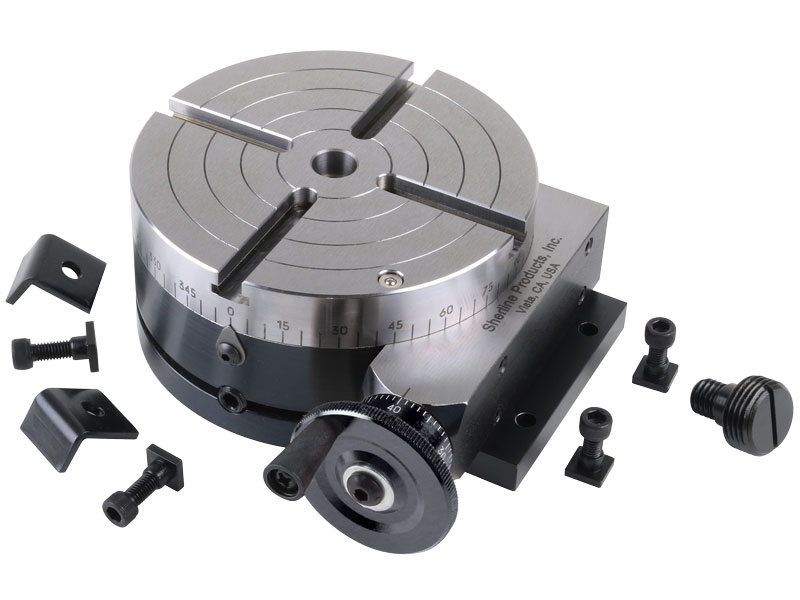
The table is 2″ high and 4″ (100mm) in diameter. The main components have been machined from solid bar stock steel, and the complete unit weighs seven pounds. The table has been engraved with a laser, giving sharp and precise lines every 5°, numbered every 15°. These lines are calibrated with the 72-tooth worm gear that is driven by the handwheel. The handwheel is divided into 50 parts, making each line on the handwheel 1/10°. This allows a circle to be divided into 3600 increments without interpolation. Seventy-two revolutions of the handwheel rotate the table one revolution.
The rotary tables can hold more weight when they are not under a continuous load. Click on the Video tab above to see examples of different weights and uses for our rotary tables.
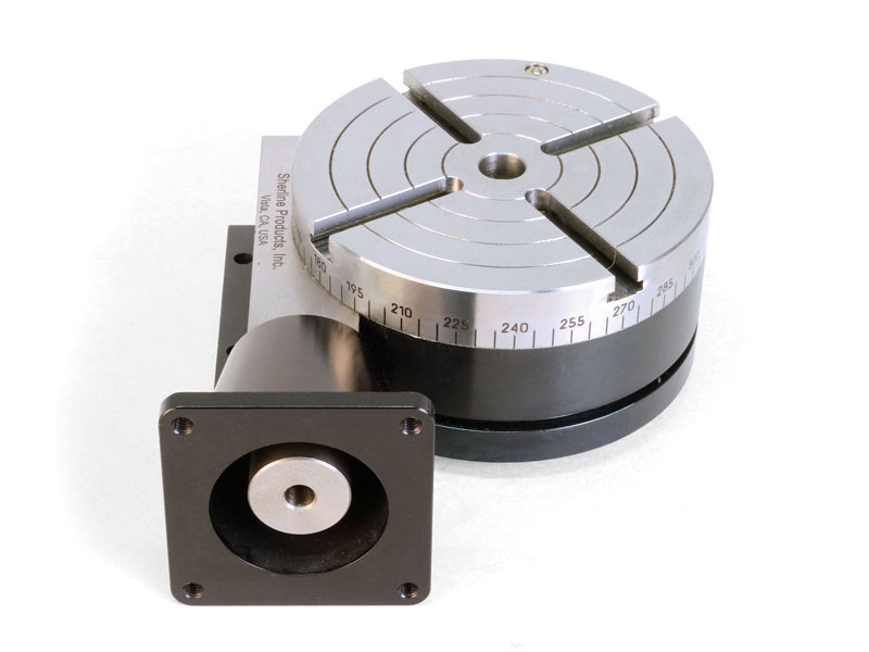
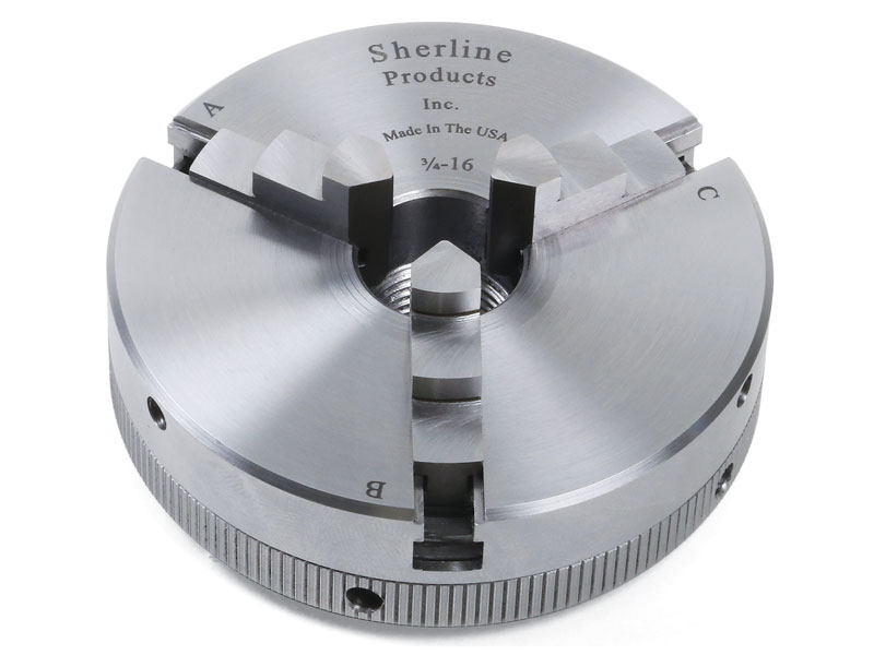
The table T-slots are identical to those used on the Sherline mill and lathe, making the vast line of Sherline tooling available for use with this product. Two hold-down clamps and T-nuts are provided with the table. Also included is an adapter that allows Sherline’s 3- and 4-jaw chucks to be screwed directly to the rotary table. An optional right-angle attachment is available (P/N 3701) to mount the table in the vertical position to increase its versatility further. With the table mounted vertically, an optional adjustable right-angle tailstock (P/N 3702) can be mounted to the mill table. It is used to support and stabilize the other end of long work held in a chuck or otherwise attached to the rotary table.

The rotary table is a great thing to have. I prefer to use it when making eccentric shafts which at my young age helps with impressing potential employers.
I used to use old valve springs and drill rod to make paint shakers and vibrating polishers with my table. Cut a 2" 304 SS to 6" L and turn 2" of it to 1". Then put it in the rotary table vertically and take ramped cuts with a 1" EM indicated with an offset of 1" and a LH cutter offset of .5 CW rotation. continue this down 2" and you now have a 1" shaft to key for the motor, a 2" journal for a heavy duty bearing, and a 1" journal eccentric lobe with a 1" stroke with which to shake things. If you make 4 of these and use them to shake a table indexed at 90 degrees you can shake up to 1000 Lbs of media/parts with little more than a 3 HP motor and a gear reduction.
Buy the biggest rotary table you can afford! Don"t worry about dividing plates, but do get a tail stock . Get an enco 4 jaw scroll chuck for it and go to town!
The stepper motor will have to be sized for your application. I used a small 3 rotary table and dont plan on using it for anything other than indexing so a high torque NEMA17 did the job. If youre working with a larger rotary table or want to be able to use it as a 4th axis in the mill you will want at least a NEMA23 size motor. You will have to reach out to the forum for help with selection.
The controller is going to have to survive swath and other nasty stuff so it will need to be in a box. You can use one like I did in my build http://www.homemodelenginemachinist.com/showthread.php?t=25783&page=2 or something as simple as a wooden box. Just keep in mind the environment that it will be being used in.
Well, if the table ratio is 40:1, doesn"t that come out to exactly 9 degrees per rotation of the handle? And having each degree on the hand wheel divided into 20 means each large mark is 3 degrees. So the vernier division of 0 - 2 would make that a 1 degree division before you get to the next large mark for 3 degrees. It sounds like fairly rational marking to me.
And having the table marked in quadrants rather than a full circle might be a matter of preference like a standard versus a direct reading dial on a cross slide. If you do more jobs like quarter rounding or carving oblong slots with radiused ends you"re customarily using just smaller portions of a circle so 287 degrees isn"t especially relevant.
It doesn"t sound like there"s any problem with the table to me, just a matter of understanding its characteristics and relating that to the job at hand. As it happens I have two devices, a rotary table with index plates and an indexer with a mounted chuck. One is a 72:1 ratio and one s 40:1. And depending on what division I want, one might be more convenient than the other for finding a hole plate with a rational number of holes.

A rotary table is a precision work positioning device used in metalworking. It enables the operator to drill or cut work at exact intervals around a fixed (usually horizontal or vertical) axis. Some rotary tables allow the use of index plates for indexing operations, and some can also be fitted with dividing plates that enable regular work positioning at divisions for which indexing plates are not available. A rotary fixture used in this fashion is more appropriately called a dividing head (indexing head).
The table shown is a manually operated type. Powered tables under the control of CNC machines are now available, and provide a fourth axis to CNC milling machines. Rotary tables are made with a solid base, which has provision for clamping onto another table or fixture. The actual table is a precision-machined disc to which the work piece is clamped (T slots are generally provided for this purpose). This disc can rotate freely, for indexing, or under the control of a worm (handwheel), with the worm wheel portion being made part of the actual table. High precision tables are driven by backlash compensating duplex worms.
The ratio between worm and table is generally 40:1, 72:1 or 90:1 but may be any ratio that can be easily divided exactly into 360°. This is for ease of use when indexing plates are available. A graduated dial and, often, a vernier scale enable the operator to position the table, and thus the work affixed to it with great accuracy.
Rotary tables are most commonly mounted "flat", with the table rotating around a vertical axis, in the same plane as the cutter of a vertical milling machine. An alternate setup is to mount the rotary table on its end (or mount it "flat" on a 90° angle plate), so that it rotates about a horizontal axis. In this configuration a tailstock can also be used, thus holding the workpiece "between centers."
With the table mounted on a secondary table, the workpiece is accurately centered on the rotary table"s axis, which in turn is centered on the cutting tool"s axis. All three axes are thus coaxial. From this point, the secondary table can be offset in either the X or Y direction to set the cutter the desired distance from the workpiece"s center. This allows concentric machining operations on the workpiece. Placing the workpiece eccentrically a set distance from the center permits more complex curves to be cut. As with other setups on a vertical mill, the milling operation can be either drilling a series of concentric, and possibly equidistant holes, or face or end milling either circular or semicircular shapes and contours.
with the addition of a compound table on top of the rotary table, the user can move the center of rotation to anywhere on the part being cut. This enables an arc to be cut at any place on the part.
Additionally, if converted to stepper motor operation, with a CNC milling machine and a tailstock, a rotary table allows many parts to be made on a mill that otherwise would require a lathe.
Rotary tables have many applications, including being used in the manufacture and inspection process of important elements in aerospace, automation and scientific industries. The use of rotary tables stretches as far as the film and animation industry, being used to obtain accuracy and precision in filming and photography.

Years ago, before I learned CNC, I owned a Phase II 8″ horizontal/vertical rotary table that I purchased from Kap Pullen’s Getmachinetools.com store. He has them at a good price, BTW, and he’s a darned nice fellow to deal with as well as being a frequent HSM contributor. Anyway, its a nice little table, but I hadn’t done a whole lot with it for quite a while after purchasing it. As is so often the case, one day, a project landed on my doorstep and I was glad to have it.
Before I could get started, however, I had to make some accessories for it. Basically, I needed some T-Nuts to fit the table, as well as a little fixture that makes it easy to hold a plate up off the table through a hole in the center so you can machine it. The latter, what I call a “plate machining fixture”, was inspired by something similar I saw the Widgitmaster of CNCZone fame using to make Dremel clamps for his mini-router:
I turned the round spigot using the 4-jaw on the lathe. I’m making the fixture out of MIC-6 aluminum plate, which is pre-ground very flat on the sides. This is a 5 inch by 3 inch piece. I’ve clamped it to the rotab using my T-nuts and the regular mill clamps and step blocks. It is sitting on parallels to make sure I don’t cut into the table. You can also see how I’ve clamped the rotary table to the mill table using a big cast iron V-block I have. You can never have to many blocks with precision faces hanging around!
Having a 4-jaw chuck on your rotary table is mighty handy! Because it’s a 4-jaw, you can dial in the workpiece by adjusting the jaws until it is perfectly concentric with the table’s axis of rotation. The best way is to make an adapter plate that attaches to the back of the chuck in the same way that your lathe does so you can exchange lathe tooling with the rotab. Here is an example:
For the example, the chuck is threaded onto the adaptor plate, and then the holes in the adapter plate’s flange are used to bolt down to T-nuts on the table.
In my case, I bought a 4-jaw from Shars brand new, and simply drilled some through-holes in the chuck to mount to the table directly without an adapter plate:
First, you want to make sure your part is properly centered on the table. To do that, I clamp the table down on the mill table (no special place is needed), put my Indicol indicator holder on the mill spindle, and find some round feature on the part to indicate on. For example, on the plate milling fixture above, indicate on the round boss, or on the center hole. Spin the table and bump the part in until spinning the table doesn’t move the indicator.
Second, locate the center of rotation directly under the mill spindle. You can simply use the X and Y table handwheels to do this. Use that Indicol to indicate off of a circular feature you want centered under the spindle. Turn the indicol around on the spindle and adjust the handwheels until the indicator stays put relative to the spindle position. A Blake Coaxial indicator will make this last even simpler.
When you’re rounding partially by cranking a part around on the rotary table, it’s really easy to go a little too far and screw things up. The answer is to drill the end points to make the exact stopping point on the rotab a lot less sensitive:
Centering with a Blake indicator is really fast, but what if you don’t have a Blake, or worse, what if your mill is too small to accomodate one? Here is a nice solution I found on a German site. This fellow has made an ER collect fixture for his rotary table, and has taken care that when installed on the table, the axis of the collet is aligned with the table’s axis. He can then place a dowel or other straight pin in the collet and line up until it will go into a similarly sized collet on the spindle. Nice trick! It’s similar to how Widgitmaster showed me to align a drill chuck on a QCTP to the lathe centerline with a dowel pin held in the lathe chuck.

Our product range includes single and multiple axes, tilt/rotating tables, and indexing and high-speed spindles. Additionally, we offer customized solution tables for customer requests or OEM projects.
Even for EDM machines that have been in use for decades, we will work with you to determine the ideal rotary indexing table and/or rotating/indexing spindle solution.
Our state-of-the-art rotary indexing tables and customizable reference and clamping systems provide endless application possibilities and highly efficient solutions.


 8613371530291