
haas 4th axis rotary table free sample
The system of rotary/indexer and Servo Control unit is defined as a semi-fourth axis. This means that the table cannot do simultaneous interpolation with other axes. Linear moves or spirals are generated by having an axis of the mill move at the same time the rotary table moves. Refer to “Simultaneous Rotation and Milling” on page 31 for details. This method requires a host machine capable of closing a relay (or switch). Most CNC machine tools are equipped with spare M codes, which can be used to close a relay. Indexing commands are stored only in the Servo Control program memory. Each pulse of the host machine relay triggers the Servo Control to index to its next programmed position. After finishing the index, the Servo Control signals that it has finished and is ready for the next pulse.This method can be used with machine tools that have no controls.
When the Servo Control executes a G94, a 250 millisecond delay is required before starting the next step. This may cause the mill axis to move before the table rotates, leaving a flat spot in the cut. If this is a problem, add a 0 to 250 milliseconds dwell (G04) after the M-Code in the mill program to prevent mill axis movement.
By adding a dwell, the rotary unit and the mill start moving at the same time. It may be necessary to alter the feed rate on the mill to avoid timing issues at the end of the spiral. Do not adjust the feed rate on the rotary control; use the mill with its finer feed rate adjustment. If the undercut appears to be in the X-Axis direction, increase the mill feed rate by 0.1. If the undercut appears in the radial direction, decrease the mill feed rate.
If timing is off by several seconds, such that the mill completes its movement before the rotary and there are several spiral moves one after another (as in retracing a spiral cut), the mill may stop. The reason is the mill sends a cycle start signal (for next cut) to the rotary control before it has completed its first move, but the rotary control does not accept another start command until it finishes the first.
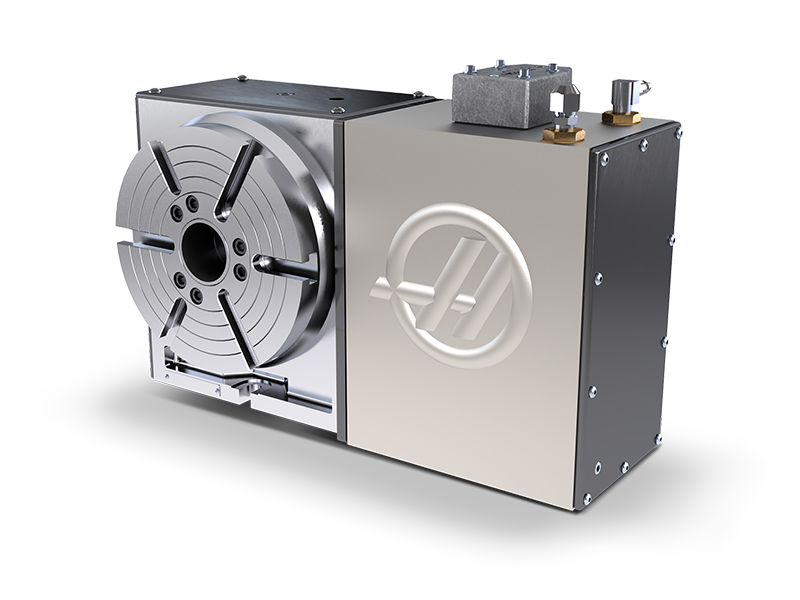
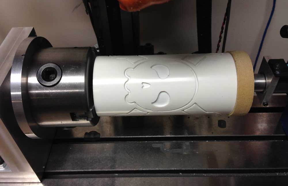
The fastest way to increase the productivity of your Haas mill is to add a Haas single or dual-axis rotary product. You can reduce or totally eliminate multiple setups, and easily handle machining multi-sided parts.
With a full line of Haas rotary products, including many specialised units designed for maximum productivity, Haas continues to lead the way to higher productivity through automation.
All Haas rotary products are designed to integrate seamlessly with the control on your Haas mill. This means true simultaneous 4-axis or 5-axis motion, synchronized with the axes of your mill. Rotary setup is a simple plug-and-play process through the Haas Control, with on-screen instructions, and diagrams that are intuitive and easy to use. It’s possible to install a Haas rotary on other makes of mill as we also offer the Haas Servo Control. Activated by a single M-code, the Servo Control is easy to set up, and fully programmable.
Adding a rotary axis to your CNC mill is the fastest way to boost throughput and increase accuracy. Because Haas began as a rotary table manufacturer in the 1980s, we are able to provide the simplest and most cost-effective entry into 4-axis and 5-axis machining available.
Going from 3-axis machining to 4-axis and 5-axis machining can be intimidating. This short video shows how easy it is to transition from basic 3-axis milling to full 5-axis design and production.
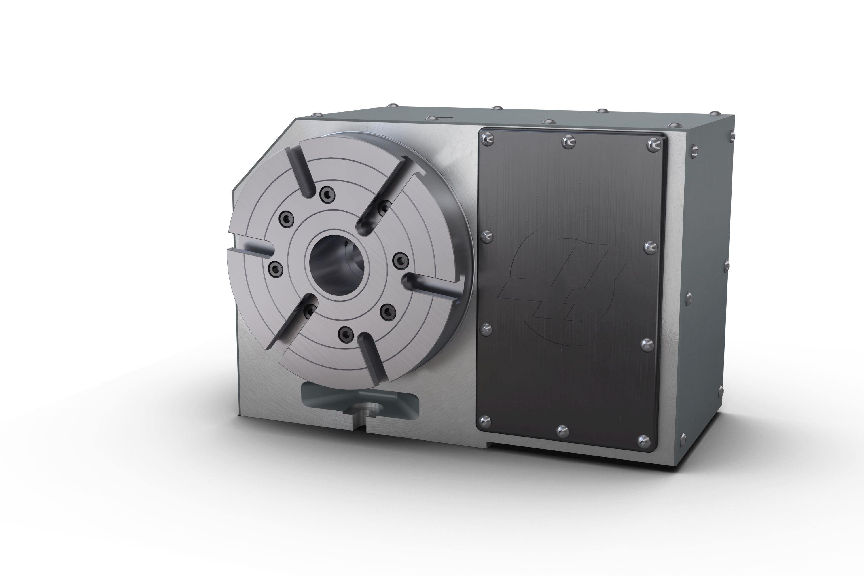
Haas offers a wide selection workholding solutions for your 4-axis and 5-axis clamping needs, from compact air-collet closers to quick-change fixture plates to manual scroll chucks.
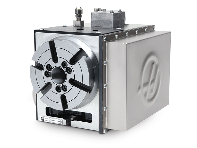
Constructed of heavy-duty materials and designed for dependable day-in, day-out operation, Haas rotary products are the benchmark by which all others are measured. We manufacture all critical components in-house at our state-of-the-art California facility. At the core of every Haas rotary table is a large-diameter, aluminium-bronze worm gear meshing with a ground alloy steel worm (hardened to 60 Rc) submerged in a synthetic oil bath.
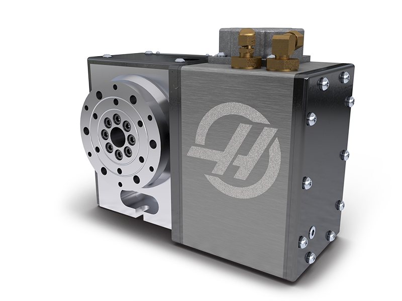
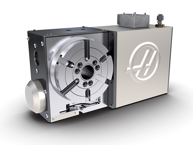
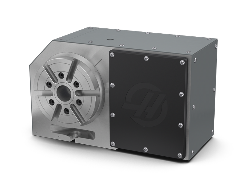
Haas HRT160SS is a high-speed 4-axis rotary table, with a cycloidal drive that provides a maximum speed of 500° per second. That’s nearly four times the speed of the standard HRT160. The compact size and high speed of the HRT160SS make it the perfect complement to the Haas DT-1 Drill/Tap Centre and moreover other high-speed Haas machines. The cycloidal rotary drive system provides a great combination of speed, accuracy, and durability.
Requires a Haas mill with 4th-axis drive and NGC software version 100.21.000.1150 or later. Stand-alone operation requires a Haas SCOL rotary control box with software version 26.22 or higher.
High-speed 4-axis rotary table – 160 mm (6.3″) Super-Speed Servo Rotary Table with 500 deg/sec indexing. Requires Haas mill with 4th-axis drive. Mills built before 1/1/2011 require software version 17.06C or later; mills built after 1/1/2011 require software version 18.01A or later. Not available for stand-alone operation.
The cycloidal rotary drive system was designed for machine tools and robotics. The drive provides a great combination of speed, accuracy, and durability. The rugged design provides long service life, with little or no maintenance. By the same token the cycloidal rotary drive can be back driven to absorb energy from an impact. Furthermore, the shock-load capacity is 5 times the rated torque of the gearbox. Should damage occur the entire gearbox is a simple drop-in replacement.
In order to participate in the auction, all BIDDERS must provide AUCTIONEER a 25% deposit in cash, cashier’s check, or company check accompanied by a bank letter of guarantee of unqualified payment to AUCTIONEER, or a wire transfer (with a wire transfer fee included) of BIDDER’S maximum expected spending inclusive of taxes and fees. Credit cards are not acceptable form of payment and will not be accepted.The final payment in full of BIDDER’S invoice must be received by AUCTIONEER within the first banking day 24 hours after the auction or BIDDER will be in default of AGREEMENT. AUCTIONEER will charge BIDDERS a taxable surcharge BUYERS PREMIUM on AUCTIONEER’S invoice to BIDDER. BIDDER shall provide proof satisfactory to AUCTIONEER of BIDDER’Sentitlement to claim exemption from sales tax. BIDDER’S proof of any claimed tax exemption must be representative of the same industry as the LOTS purchased. In the absence of proof satisfactory to AUCTIONEER, BIDDER shall pay all taxes. AUCTIONEER is not responsible for any Department of Motor Vehicle fees, taxes, registration, licensing, penalties, smog certificate, or any other fees. Certain vehicles as announced and/or noted in the auction catalog or on BIDDER’S invoice will be sold “AS IS” with a Bill of Sale only. Each titled item will be charged a $75 title transfer fee. If available to AUCTIONEER, titles will be sent to BIDDER approximately 7-30 business days after receipt of payment from BIDDER to AUCTIONEER. Sales tax on Motor Vehicles is the responsibility of BIDDER to be remitted to BIDDER’S appropriate state Department of Motor Vehicles. All vehicles are sold “AS IS, WHERE IS, WITH NO WARRANTIES EXPRESSED OR IMPLIED”. It is the BIDDER’S responsibility to inspect the vehicle to verify accurate description, model, year, mileage, condition and any and all details pertaining to the vehicle. AUCTIONEER is not responsible for any inaccuracies regarding LOTS of any kind INCLUDING THE DESCRIPTIONS ON THE FINAL INVOICE.
Should any pits, floor bolts or hazards of any type exist after removal of equipment, it is BIDDER’Sresponsibility, at BIDDER’S cost, to reasonably safe guard these areas using generally accepted safety practices, such as safety tapes, pipes or bars welded in place or suitable safety barriers acceptable to AUCTIONEER. All floor bolts and/or anchoring fasteners are to be cut flush to the floor and the area left broom clean and all debris removed. It is the responsibility of BIDDER to be sure that power to the LOTSis off and then to safely disconnect all electrical wiring and utility piping from the LOTSand to cap at the first electrical or air junction of the LOTS.
Seriously why doesn"t Haas follow right hand rule. when I started at the shop im at now they had two vf2 with the small haas 5th axis trunnions(TR200Y). They both rotate backwards i.e. positive rotation on A axis brings the bottom of trunnion up toward operator and the platter faces toward back of the machine. But now I Have to program for our larger 5th axis trunnion(TRT160) on the VF4 and positive rotation is opposite of what are smaller VF2 machines do. What do you guys suggest? As of now after reading this post from 12 years ago my plan is to just make a copy of my current post, CD and MD then rename and reverse it in the MD.
As an aside to anyone who might read this thread, I"m learning this might not strictly be a Fusion 360 issue per se. Someone on the Practical Machinist forums suggested I right a simultaneous rotary movement by hand to test how smooth it ran, and long story short, I wrote this in MDI:
The first G1 is roughly half the feed I want in theory (21.5 ipm) and the second and third G1 are the roughly the full feed I wanted (43 ipm), assuming my part diameter is 1.181 (not including my tool/toolpath diameter). There were no stops between the first and second G1, and there was a stop and start between the second and third G1, but those were otherwise smooth. This means that the machine will run perfectly smooth at the higher feed rate provided there is only one line of code, and at half the feed rate, it will run smooth in spite of many lines of code (like I mentioned in an earlier post where I tried the toolpath at half feed rate). With programmed higher feed but 50% feed on the machine override, the toolpath is smoother and more connected, but not quite as good as programming 50% feed. This leads me to believe the smoothness of the toolpath is tied to the feed at the machine in addition to the lines of code. I also accidentally programmed a feed twice as high as I wanted in MDI, which worked out to be faster than the rotary could theoretically handle, and even that was smooth since it was only one line of code.
So, I"m kinda lost. I don"t think it"s really a Fusion 360 problem so much as a Haas trying to figure out all these lines of Inverse Time Feed code, but I don"t know why that would change depending on the feed rate, either programmed or in the override.


 8613371530291