
rotary table for cnc milling machine free sample

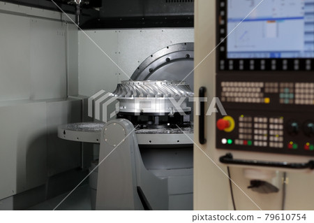
The 4-axis CNC milling machine cutting the sample parts with ball endmill tools. The 3-axis machining center attach the rotary table for cutting the sample parts.
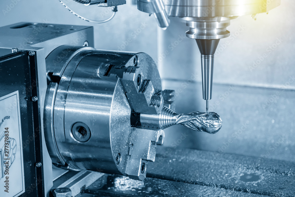
With this extension, your CNC milling machine gets the 4th axis. That allows you, for example, to mill round parts or create engravings on rounded surfaces.
This rotary axis is made to order for us by a German precision mechanic. In this price segment, this rotation axis for CNC milling machines is unrivalled in Europe!
There are many rotary tables on the market. If possible, they have to be inexpensive. You can get a lot of them! Usefulness? That is where the wheat is separated from the chaff. For example, there are many CNC turntables with the cheapest belt transmission. The disadvantages are obvious: slippage due to the belt. If not in the belt drive itself, then on the load or idle side of the belt. Perhaps useful for engraving work. For milling, however, usually not or limited in the choice of material (aluminium 3D milling not possible).
Made with the highest quality made in Germany with high-precision, a ground worm drive and holding torque of over 20Nm using only high-quality components. That is the reason you can machine round parts with the lowest tolerances.
That means you can use the CNC router for 3D 360° machining in almost all materials. Even round engravings on Plexiglas are possible without any problems with this CNC accessory. That means for our CNC machine users: Round surface milling of plastic parts, wooden parts, aluminium parts or round parts made of brass, as well as engravings of all kinds.
This website is using a security service to protect itself from online attacks. The action you just performed triggered the security solution. There are several actions that could trigger this block including submitting a certain word or phrase, a SQL command or malformed data.

The 4-axis CNC milling machine cutting the sample parts with ball endmill tools. The 3-axis machining center attach the rotary table for cutting the sample parts.
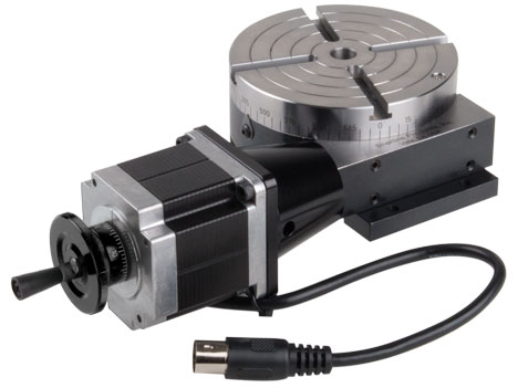
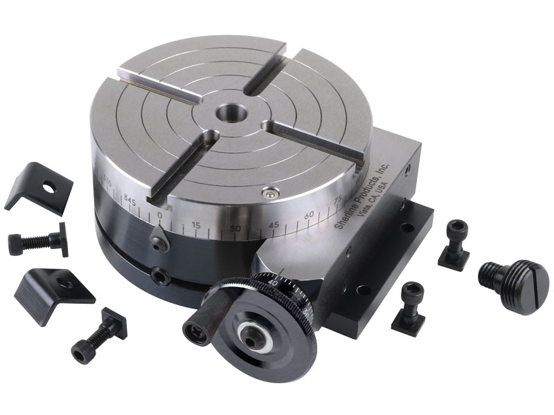
Sherline has taken its P/N 3700 manual 4″ rotary table and applied a stepper motor mount with dampened coupling in place of the handwheel. The mount accepts a NEMA #23 frame-size stepper motor for CNC control. This allows the table to be used as a 4th axis with CNC systems that have the capability to drive a rotary axis.
The rotary tables can hold more weight when they are not under a continual load. Click on the Video tab above to see examples of different weights and uses for our rotary tables.

Years ago, before I learned CNC, I owned a Phase II 8″ horizontal/vertical rotary table that I purchased from Kap Pullen’s Getmachinetools.com store. He has them at a good price, BTW, and he’s a darned nice fellow to deal with as well as being a frequent HSM contributor. Anyway, its a nice little table, but I hadn’t done a whole lot with it for quite a while after purchasing it. As is so often the case, one day, a project landed on my doorstep and I was glad to have it.
Before I could get started, however, I had to make some accessories for it. Basically, I needed some T-Nuts to fit the table, as well as a little fixture that makes it easy to hold a plate up off the table through a hole in the center so you can machine it. The latter, what I call a “plate machining fixture”, was inspired by something similar I saw the Widgitmaster of CNCZone fame using to make Dremel clamps for his mini-router:
I turned the round spigot using the 4-jaw on the lathe. I’m making the fixture out of MIC-6 aluminum plate, which is pre-ground very flat on the sides. This is a 5 inch by 3 inch piece. I’ve clamped it to the rotab using my T-nuts and the regular mill clamps and step blocks. It is sitting on parallels to make sure I don’t cut into the table. You can also see how I’ve clamped the rotary table to the mill table using a big cast iron V-block I have. You can never have to many blocks with precision faces hanging around!
Having a 4-jaw chuck on your rotary table is mighty handy! Because it’s a 4-jaw, you can dial in the workpiece by adjusting the jaws until it is perfectly concentric with the table’s axis of rotation. The best way is to make an adapter plate that attaches to the back of the chuck in the same way that your lathe does so you can exchange lathe tooling with the rotab. Here is an example:
For the example, the chuck is threaded onto the adaptor plate, and then the holes in the adapter plate’s flange are used to bolt down to T-nuts on the table.
In my case, I bought a 4-jaw from Shars brand new, and simply drilled some through-holes in the chuck to mount to the table directly without an adapter plate:
First, you want to make sure your part is properly centered on the table. To do that, I clamp the table down on the mill table (no special place is needed), put my Indicol indicator holder on the mill spindle, and find some round feature on the part to indicate on. For example, on the plate milling fixture above, indicate on the round boss, or on the center hole. Spin the table and bump the part in until spinning the table doesn’t move the indicator.
Second, locate the center of rotation directly under the mill spindle. You can simply use the X and Y table handwheels to do this. Use that Indicol to indicate off of a circular feature you want centered under the spindle. Turn the indicol around on the spindle and adjust the handwheels until the indicator stays put relative to the spindle position. A Blake Coaxial indicator will make this last even simpler.
When you’re rounding partially by cranking a part around on the rotary table, it’s really easy to go a little too far and screw things up. The answer is to drill the end points to make the exact stopping point on the rotab a lot less sensitive:
Centering with a Blake indicator is really fast, but what if you don’t have a Blake, or worse, what if your mill is too small to accomodate one? Here is a nice solution I found on a German site. This fellow has made an ER collect fixture for his rotary table, and has taken care that when installed on the table, the axis of the collet is aligned with the table’s axis. He can then place a dowel or other straight pin in the collet and line up until it will go into a similarly sized collet on the spindle. Nice trick! It’s similar to how Widgitmaster showed me to align a drill chuck on a QCTP to the lathe centerline with a dowel pin held in the lathe chuck.

One of the most reliable ways machine tool builders maintain workpiece stability is to build a sturdy, heavy frame and a solid bed to reduce the miniscule movements during machining that can cause tool deflection or chatter. However, five-axis machines have a somewhat less-stable worktable design. This is because of the rotation they must provide to position part at different angles.
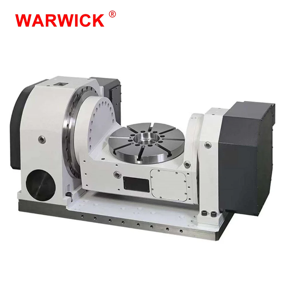
According to Makino, different five-axis configurations have different benefits and challenges to consider, being that tilting the worktable along the A or B axes can compromise rigidity. For example, at certain positions, a swinging trunnion table can introduce leverage that amplifies micro-movements in the workpiece when the cutting tool makes contact, possibly resulting in deflection and chatter. While this loss of rigidity can be frustrating, the benefits of the complex contouring and single-setup machining are often more than enough to justify the investment. However, Makino recently developed the D200Z, which it says is designed to eliminate the need for a compromise. The company displayed the machine at Amerimold 2018, where it demonstrated how the CNC vertical machining center (VMC) achieves five-axis movement through a set of two integral rotating tables, one of which is tilted at a 44.5-degree angle.
According to the company, the permanent 44.5-degree tilt is a critical aspect of this rotary-table design. The tilted plate rotates about the B axis, while the rotary table attached to it rotates along the C axis, together enabling full five-axis machining and 3+2 machining. While a trunnion design involves making wide swings that drastically alter the center of gravity of the table, the D200Z can rotate fully around both axes within a comparatively small area. This improves stability by maintaining a center of gravity entirely within the physical diameter of the table’s bearings. The primary limitations are the size and mass of the workpiece. If it is larger than 165 pounds (75 kg), the benefits of the tilted rotary table begin to decrease compared to larger trunnions or articulated spindles.
Machine rigidity is particularly important in moldmaking applications. High-speed machining to precise tolerances requires anticipating chatter or deflection to avoid scrapping an expensive mold core or cavity. “The table design ensures that the center of gravity is always within the capture range of the bearings,” says Bill Howard, Makino product line manager. “Therefore, regardless of the desired angle or rotary position, the design provides and maintains stiffness and rigidity, as well as ensures excellent kinematics and motion control.” By balancing the need for maintaining rigidity, the D200Z is designed to reduce chatter and deflection in mold machining, as well as other applications that require high precision or have complex part geometries.
Additionally, the tilted rotary table is said to ensure sufficient clearance for the spindle to access critical part features. With a free-standing rotary surface that only attaches to the rest of the machine from the bottom-center of the table, the spindle is designed to easily access five sides of a part, and the cutting tool can reach deep into pockets for molds. The table’s geometric simplicity also simplifies chip evacuation, as moving to a vertical position enables chips to fall into a conveyor, available as a standard feature.
The compact work area also reduces the machine’s footprint, leaving room for attached tool changers or automation cells. Further, the small work area and tilted table reduce the distance operators have to reach in order to load and unload parts, reducing the physical toll and increasing the ergonomics for the user.
Additionally, the compact workspace increases manufacturing speed. Because the machine tool is capable of achieving full five-axis movement and positioning in a small work area, it requires relatively small movements to reach desired orientations. The small movements translate into fast positioning for the workpiece.
Mr. Howard asserts that anyone used to working with five-axis CNC machines should have no problem programming this one. “I would think that anyone familiar with any CAD/CAM system that generates and evaluates tool paths for five-axis machines would have no difficulty programming the D200Z,” he says.
Once seen as a specialty machine tool, the CNC Swiss-type is increasingly being used in shops that are full of more conventional CNC machines. For the newcomer to Swiss-type machining, here is what the learning curve is like.

The item has been restored to working order by the eBay seller or a third party. This means the item was inspected, cleaned, and repaired to full working order and is in excellent condition. This item may or may not be in original packaging. See seller’s listing for full details.See all condition definitionsopens in a new window or tab

Centroid OEM Machine Tool Manufactures offer a wide variety of Centroid CNC equipped machine tools.. click to to find a Centroid equipped CNC machine tools..
Small Milling Machine CNC Control system: $18,385M400 3 axis with 1Kw AC Brushless Yaskawa servo motors and drivesMedium Milling Machine CNC control system: $22,175M400 3 axis with 2Kw AC Brushless Yaskawa servo motors and drivesLarge Milling Machine CNC Control system: $25,760M400 3 axis with 4.4Kw AC Brushless Yaskawa servo motors and drives
Small Slant Bed Lathe CNC control system: $15,450T400 2 axis with 1Kw AC Brushless Yaskawa servo motors and drivesMedium Slant Bed Lathe CNC control system: $18,795T400 2 axis with 2.2Kw, 2.2kw w/brake AC Brushless Yaskawa servo motors and drivesLarge Slant Bed or VTL CNC control system: $21,597T400 2 axis with 4.4Kw, 4.4 Kw w brake AC Brushless Yaskawa servo motors and drives
Knee Mills, Bed Mills, Routers:M400S $13,709 IN STOCK! Ready to Ship, use order #StockSFlat Bed Lathes, Small Slant Bed Lathes: T400S $13,279,click for pdf quote
Auto part set, Auto tool set, 3D contouring, 4th and 5th axis machining, Available in OEM configurations, Professional Installation with Service & Training and DIY CNC kits for both new machines and retrofit upgrades.
From the May issue of Modern Machine Shop Magazine " A CNC retrofit provides improved reliability and functionality compared to an older machine’s original control, and this is helpful in a number of ways. For example, a more intuitive control interface can help speed setups and minimize the chance for programming and/or setup mistakes, which could possibly damage or scrap a high-value work piece. Similarly, shops are also more confident in quoting work for large, expensive parts knowing the new control won’t hiccup partway through an operation and cause the part to be damaged. Shops also are better-positioned to take in “hot” jobs that require fast turnaround due to the retrofitted machine’s improved"... click here to see the complete article in PDF.
CENTROID Boss series II retrofit customer testimonial"The quality and workmanship of the CENTROID equipment was outstanding and very professional. CENTROID was able to custom tailor the control to allow us to continue to use our rotary milling arrangement as before and even expanded our capability. The short story is that we ended up with a four axis CNC mill for less than half the cost of the three axis Haas. This includes the work that was done by our staff."

(2) DELL PC: with Gibbs CAM 3D solid machining software and AutoCAD/LT Note: Please e-mail cad files in .IGS,.X_T,.XMT,.PAR,.SLDPRT,.DXF, or .DWG formats
You can use this royalty-free photo "The 4-axis CNC milling machine cutting the sample parts ." for personal and commercial purposes according to the Standard or Extended License. The Standard License covers most use cases, including advertising, UI designs, and product packaging, and allows up to 500,000 print copies. The Extended License permits all use cases under the Standard License with unlimited print rights and allows you to use the downloaded stock images for merchandise, product resale, or free distribution.

CNC 101: The term CNC stands for "computer numerical control", and the CNC machining definition is that it is a subtractive manufacturing process that typically employs computerized controls and machine tools to remove layers of material from a stock piece—known as the blank or workpiece—and produces a custom-designed part. This process is suitable for a wide range of materials, including metals, plastics, wood, glass, foam, and composites, and finds application in a variety of industries, such as large CNC machining, machining of parts and prototypes for telecommunications, and CNC machining aerospace parts, which require tighter tolerances than other industries. Note there is a difference between the CNC machining definition and the CNC machine definition—one is a process and the other is a machine. A CNC machine (sometimes incorrectly referred to as a C and C machine) is a programmable machine that is capable of autonomously performing the operations of CNC machining.
CNC machining as a manufacturing process and service is available worldwide. You can readily find CNC machining services in Europe, as well as in Asia, North America, and elsewhere around the globe.
Subtractive manufacturing processes, such as CNC machining, are often presented in contrast to additive manufacturing processes, such as 3D printing, or formative manufacturing processes, such as liquid injection molding. While subtractive processes remove layers of material from the workpiece to produce custom shapes and designs, additive processes assemble layers of material to produce the desired form and formative processes deform and displace stock material into the desired shape. The automated nature of CNC machining enables the production of high precision and high accuracy, simple parts and cost-effectiveness when fulfilling one-off and medium-volume production runs. However, while CNC machining demonstrates certain advantages over other manufacturing processes, the degree of complexity and intricacy attainable for part design and the cost-effectiveness of producing complex parts is limited.
While each type of manufacturing process has its advantages and disadvantages, this article focuses on the CNC machining process, outlining the basics of the process, and the various components and tooling of the CNC machine. Additionally, this article explores various mechanical CNC machining operations and presents alternatives to the CNC machining process.
Are you between jobs right now or an employer looking to hire? We"ve got you covered with our in-depth collections of resources for industrial job seekers and employers looking to fill roles. If you have an open position, you can also fill out our form for a chance to have it featured in the Thomas Monthly Update newsletter.
Evolving from the numerical control (NC) machining process which utilized punched tape cards, CNC machining is a manufacturing process which utilizes computerized controls to operate and manipulate machine and cutting tools to shape stock material—e.g., metal, plastic, wood, foam, composite, etc.—into custom parts and designs. While the CNC machining process offers various capabilities and operations, the fundamental principles of the process remain largely the same throughout all of them. The basic CNC machining process includes the following stages:
The CNC machining process begins with the creation of a 2D vector or 3D solid part CAD design either in-house or by a CAD/CAM design service company. Computer-aided design (CAD) software allows designers and manufacturers to produce a model or rendering of their parts and products along with the necessary technical specifications, such as dimensions and geometries, for producing the part or product.
Designs for CNC machined parts are restricted by the capabilities (or inabilities) of the CNC machine and tooling. For example, most CNC machine tooling is cylindrical therefore the part geometries possible via the CNC machining process are limited as the tooling creates curved corner sections. Additionally, the properties of the material being machined, tooling design, and workholding capabilities of the machine further restrict the design possibilities, such as the minimum part thicknesses, maximum part size, and inclusion and complexity of internal cavities and features.
When specifying parts to a machine shop, it"s important to include any necessary tolerances. Though CNC machines are very accurate, they still leave some slight variation between duplicates of the same part, generally around + or - .005 in (.127 mm), which is roughly twice the width of a human hair. To save on costs, buyers should only specify tolerances in areas of the part that will need to be especially accurate because they will come into contact with other parts. While there are standard tolerances for different levels of machining (as shown in the tables below), not all tolerances are equal. If, for example, a part absolutely cannot be larger than the measurement, it might have a specified tolerance of +0.0/-0.5 to show it can be slightly smaller, but no larger in that area.
The formatted CAD design file runs through a program, typically computer-aided manufacturing (CAM) software, to extract the part geometry and generates the digital programming code which will control the CNC machine and manipulate the tooling to produce the custom-designed part.
CNC machines used several programming languages, including G-code and M-code. The most well-known of the CNC programming languages, general or geometric code, referred to as G-code, controls when, where, and how the machine tools move—e.g., when to turn on or off, how fast to travel to a particular location, what paths to take, etc.—across the workpiece. Miscellaneous function code, referred to as M-code, controls the auxiliary functions of the machine, such as automating the removal and replacement of the machine cover at the start and end of production, respectively.
Before the operator runs the CNC program, they must prepare the CNC machine for operation. These preparations include affixing the workpiece directly into the machine, onto machinery spindles, or into machine vises or similar workholding devices, and attaching the required tooling, such as drill bits and end mills, to the proper machine components.
The CNC program acts as instructions for the CNC machine; it submits machine commands dictating the tooling’s actions and movements to the machine’s integrated computer, which operates and manipulates the machine tooling. Initiating the program prompts the CNC machine to begin the CNC machining process, and the program guides the machine throughout the process as it executes the necessary machine operations to produce a custom-designed part or product.
CNC machining processes can be performed in-house—if the company invests in obtaining and maintaining their own CNC equipment—or outsourced to dedicated CNC machining service providers.
CNC machining is a manufacturing process suitable for a wide variety of industries, including automotive, aerospace, construction, and agriculture, and able to produce a range of products, such as automobile frames, surgical equipment, airplane engines, gears, and hand and garden tools. The process encompasses several different computer-controlled machining operations—including mechanical, chemical, electrical, and thermal processes—which remove the necessary material from the workpiece to produce a custom-designed part or product. While chemical, electrical, and thermal machining processes are covered in a later section, this section explores some of the most common mechanical CNC machining operations including:
Drilling is a machining process which employs multi-point drill bits to produce cylindrical holes in the workpiece. In CNC drilling, typically the CNC machine feeds the rotating drill bit perpendicularly to the plane of the workpiece’s surface, which produces vertically-aligned holes with diameters equal to the diameter of the drill bit employed for the drilling operation. However, angular drilling operations can also be performed through the use of specialized machine configurations and workholding devices. Operational capabilities of the drilling process include counterboring, countersinking, reaming, and tapping.
Milling is a machining process which employs rotating multi-point cutting tools to remove material from the workpiece. In CNC milling, the CNC machine typically feeds the workpiece to the cutting tool in the same direction as the cutting tool’s rotation, whereas in manual milling the machine feeds the workpiece in the opposite direction to the cutting tool’s rotation. Operational capabilities of the milling process include face milling—cutting shallow, flat surfaces and flat-bottomed cavities into the workpiece—and peripheral milling—cutting deep cavities, such as slots and threads, into the workpiece.
Turning is a machining process which employs single-point cutting tools to remove material from the rotating workpiece. In CNC turning, the machine—typically a CNC lathe machine—feeds the cutting tool in a linear motion along the surface of the rotating workpiece, removing material around the circumference until the desired diameter is achieved, to produce cylindrical parts with external and internal features, such as slots, tapers, and threads. Operational capabilities of the turning process include boring, facing, grooving, and thread cutting. When it comes down to a CNC mill vs. lathe, milling, with its rotating cutting tools, works better for more complex parts. However, lathes, with rotating workpieces and stationary cutting tools, work best for faster, more accurate creation of round parts.
Close cousins to lathes, CNC spinning lathe machines involve a lathe set with a blank (a metal sheet or tube) that rotates at high speeds while a metal spinning roller shapes the workpiece into a desired shape. As a “cold” process, CNC metal spinning forms pre-formed metal—the friction of the spinning lathe contacting the roller creates the force necessary to shape the part.
Swiss machining, also known as swiss screw machining, uses a specialized type of lathe that allows the workpiece to move back and forth as well as rotate, to enable closer tolerances and better stability while cutting. Workpieces are cut right next to the bushing holding them instead of farther away. This allows for less stress on the part being made. Swiss machining is best for small parts in large quantities, like watch screws, as well as for applications with critical straightness or concentricity tolerances. You can find out more about this topic in our guide on how swiss screw machines work.
5 axis CNC machining describes a numerically-controlled computerized manufacturing system that adds to the traditional machine tool’s 3-axis linear motions (X, Y, Z) two rotational axes to provide the machine tool access to five out of six part sides in a single operation. By adding a tilting, rotating work holding fixture (or trunnion) to the work table, the mill becomes what is called a 3+2, or an indexed or positional, machine, enabling the milling cutter to approach five out of six sides of a prismatic workpiece at 90° without an operator having to reset the workpiece.
It is not quite a 5-axis mill, however, because the fourth and fifth axes do not move during machining operations. Adding servomotors to the additional axes, plus the computerized control for them – the CNC part –would make it one. Such a machine- which is capable of full simultaneous contouring- is sometimes called a “continuous” or “simultaneous” 5-axis CNC mill. The two additional axes can also be incorporated at the machining head, or split – one axis on the table and one on the head.
To handle a CNC lathe, a machinist should have completed a set amount of coursework and earned appropriate certification from an accredited industrial training organization. CNC turning machining training programs will usually involve multiple classes or sessions, offering a gradual instruction process broken up into several steps. The importance of adhering to safety protocols is reinforced throughout the training process.
Beginning CNC lathe classes might not include hands-on experience, but they may include familiarizing students with the command codes, translating CAD files, tool selection, cutting sequences, and other areas. A beginner CNC lathe course may include:
Later CNC lathe training typically involves actual lathe operation, as well as machine adjustments, program editing, and the development of new command syntax. This type of lathe machine training can include courses on:
As indicated above, there is a wide range of machining operations available. Depending on the machining operation being performed, the CNC machining process employs a variety of software applications, machines, and machine tools to produce the desired shape or design.
The CNC machining process employs software applications to ensure the optimization, precision, and accuracy of the custom-designed part or product. Software applications used include:
CAD: Computer-aided design (CAD) software are programs used to draft and produce 2D vector or 3D solid part and surface renderings, as well as the necessary technical documentation and specifications associated with the part. The designs and models generated in a CAD program are typically used by a CAM program to create the necessary machine program to produce the part via a CNC machining method. CAD software can also be used to determine and define optimal part properties, evaluate and verify part designs, simulate products without a prototype, and provide design data to manufacturers and job shops.
CAM: Computer-aided manufacturing (CAM) software are programs used extract the technical information from the CAD model and generate machine program necessary to run the CNC machine and manipulate the tooling to produce the custom-designed part. CAM software enables the CNC machine to run without operator assistance and can help automate finished product evaluation.
Depending on the machining operation being performed, the CNC machining process employs a variety of CNC machines and machine tools to produce the custom-designed part or product. While the equipment may vary in other ways from operation to operation and application to application, the integration of computer numerical control components and software (as outlined above) remains consistent across all CNC machining equipment and processes.
Drilling employs rotating drill bits to produce the cylindrical holes in the workpiece. The design of the drill bit allows for the waste metal—i.e., chips—to fall away from the workpiece. There are several types of drill bits, each of which is used for a specific application. Types of drill bits available include spotting drills (for producing shallow or pilot holes), peck drills (for reducing the amount of chips on the workpiece), screw machine drills (for producing holes without a pilot hole), and chucking reamers (for enlarging previously produced holes).
Typically the CNC drilling process also utilizes CNC-enabled drill presses, which are specifically designed to perform the drilling operation. However, the operation can also be performed by turning, tapping, or milling machines.
Milling employs rotating multi-point cutting tools to shape the workpiece. Milling tools are either horizontally or vertically oriented and include end mills, helical mills, and chamfer mills.
The CNC milling process also utilizes CNC-enabled milling machinery, referred to as mill machines or mills, which can be horizontally or vertically oriented. Basic mills are capable of three-axis movements, with more advanced models accommodating additional axes. The types of mills available include hand milling, plain milling, universal milling, and omniversal milling machines.
Turning employs single-point cutting tools to remove material from the rotating workpiece. The design of the turning tool varies based on the particular application, with tools available for roughing, finishing, facing, threading, forming, undercutting, parting, and grooving applications.
The CNC turning process also utilizes CNC-enabled lathes or turning machines. The types of lathes available include turret lathes, engine lathes, and special-purpose lathes.
Companies that specialize in manufacturing CNC machines often offer a desktop series of smaller, lightweight machines. Desktop CNC machines, although slower and less precise, handle soft materials well, such as plastic and foam. They’re also better for smaller parts and light to moderate production. Machines featured in a tabletop series resemble the larger industry standard, but their size and weight make them better suited to small applications. A desktop CNC lathe, for example, that features two axes and can handle parts up to six inches in diameter, would be useful for jewelry and mold-making. Other common desk CNC machines include plotter-sized laser cutters and milling machines.
With smaller lathes, it’s important to differentiate between a benchtop CNC lathe machine and a desktop lathe. Benchtop CNC lathes are generally more affordable, but also smaller and somewhat limited in the applications they can handle. A standard CNC benchtop lathe generally includes the motion controller, cables, and basic software. A standard CNC desktop lathe, with a similar basic package, costs slightly more.
The optimal material for selection to apply to a CNC manufacturing application is largely dependent on the particular manufacturing application and its specifications. Most materials can be machined provided that they can withstand the machining process—i.e., have sufficient hardness, tensile strength, shear strength, and chemical and temperature resistance.
The workpiece material and its physical properties are used to determine the optimal cutting speed, cutting feed rate, and depth of cut. Measured in surface feet per minute, the cutting speed refers to how fast the machine tool cuts into or removes material from the workpiece. The feed rate—measured in inches per minute—is a measure of how fast the workpiece is fed towards the machine tool, and the cut depth is how deep the cutting tool cuts into the workpiece. Typically, the workpiece will first undergo an initial phase in which it is roughly machined to the approximate, custom-designed shape and dimensions, and then undertake a finishing phase in which it experiences slower feed rates and shallower cut depths to achieve its more precise and accurate specifications.
The wide range of capabilities and operations offered by the CNC machining process help it to find application in a variety of industries, including automotive, aerospace, construction, and agriculture, and enable it to produce a range of products, such as hydraulic components, screws, and shafts. Despite the versatility and customizability of the process, the manufacturing of some parts—e.g., large or heavy components—present greater challenges than others. Table 1, below, outlines some of the challenges of machining large parts and heavy components.
Although CNC machining demonstrates advantages over other manufacturing processes, it may not be appropriate for every manufacturing application, and other processes may prove more suitable and cost-effective. While this article focuses on the mechanical CNC machining processes which employ machine tools to produce the custom-designed part or product, CNC controls can be integrated into a variety of machines. Other mechanical CNC machining processes include ultrasonic machining, waterjet cutting, and abrasive jet machining.
Besides mechanical processes, chemical, electrochemical, and thermal machining processes are also available. Chemical machining processes include chemical milling, blanking, and engraving; electrochemical machining processes include electrochemical deburring and grinding; and thermal machining processes include electron beam machining, laser cutting, plasma arc cutting, and electrical discharge machining (EDM).
Outlined above are the basics of the CNC machining process, various CNC machining operations and their required equipment, and some of the considerations that may be taken into account by manufacturers and machine shops when deciding whether CNC machining is the most optimal solution for their particular manufacturing application.
To find more information on domestic commercial and industrial suppliers of custom manufacturing services and equipment, visit the Thomas Supplier Discovery Platform, where you will find information on over 500,000 commercial and industrial suppliers.
To control CNC machines we use commands called CNC G Codes. Although Different manufactures of the machine tool may adopt their own use for certain G Codes there is a core group that is common on every machine tool. These standards are used on CNC Lathes, Milling machines, routers and more recently by 3D printers (in a very basic form). Today we are going to examine this group and how they are used to control the machines.
This command is used when the tool is not touching the part to rapid move, normally used when going home for a tool change and returning with a new tool. Some machinists like to rapid as close to the part as possible but I advise giving yourself at least 1mm clearance. Keep your hand on the feed knob and come in slow for the first time run. It is in this mode you will do the most damage if you didn’t get your tool set up right.
G00 is the rapid travel command in G Code. It is used when the cutter or tool is not removing material so that the time it takes to machine the part is as quick as can be. The top speed is set by the machine parameters and therefore is only controllable by the operator using a rapid override control.
You don’t need to add this command on every line, as long as there is no other movement G-Code active, for example, you only need to add it after a G02, G03 or a G00 command.
When programming a profile it is easier to use cutter compensation G41 and G42 then you do not need to allow for the radius of the cutter when plotting your tool paths, you can simply use the dimensions on the drawing and the machine will offset the cutter to achieve the correct dimensions.
When using G02 with G01 and G03 (Counter clockwise arc) any shape can be machined. These three G Codes are the foundation of G Code programming and are the three you will use when cutting material.
Sometimes we need to pause the cutter for a brief moment, for that we add a dwell to the code to stop the machine from continuing reading the program for a specified amount of time.
While drilling with a flat bottom drill and the surface of the bore has a chattered finish, we can stop moving the drill in Z-Axis with it still rotating for half a second to clean up the surface.
The feed rate does not need to be specified again after a dwell command as the machine still knows that one was defined before the dwell on the G01 block.
Although it is only needed once in the program it is good practice to add this information after every tool change. This makes it safer to run from any position in the program.
For example, you might want to repeat the finishing cutter pass to remove more material after measurement. To define the unit of measurement again will stop the machine from accidentally being in the wrong system and moving unexpectedly.
G90 selects the absolute positioning system. In this mode, all movements of the spindle are taken from the datum position. For example, if X100.0 is read by the control then the tool will move to 100mm in the plus direction from the datum. If X150.0 was the next positional movement it would move the tool another 50mm in that direction.
G91 selects the incremental positioning system. When G91 is active all movements of the spindle are taken from its last known position. For example, If X100.0 is read then the tool will move 100mm in the plus direction of the position that the tool is already in. If X150.0 was read after this move, The tool will move another 150mm in the plus direction.
Without using cutter compensation when programming we would have to allow for the diameter of the tool when writing the cutting paths. We can program to the dimensions of the component by using cutter compensation.
Multiple repetitive cycles enable the programmer to remove a lot of material with just a few lines of g-code, often reusing the profile as a subroutine. These repetitive cycles allow the machine to take care of the tool paths which speeds up the programming process. To learn more about each individual multiple repetitive cycle,
Canned cycles enable us to write g-code to drill and bore many holes with minimum lines of g-code. They allow us to give all the information on a single line, then the following lines are positional.

2022 best desktop CNC router with 2x3 4th axis rotary table is an entry level CNC machine kit designed for for craftsman, home shop, hobby, small business, advertising, woodworking, arts, gifts, crafts, sign making, and mold making.
STG6090 desktop CNC router kit is an entry level CNC router machine with 2x3 rotary table for hobbyists, small business, home business, small shop, home shop and craftsman. The rotary 4th axis CNC router table adopts whole cast iron machine bed, cast aluminum gantry with dustproof system, under impact resistance beam more stronger with higher machining precision. The 4th roatry axis CNC router machine adopts high quality ball screw and high accuracy segmentation to achieve the final high precision machining result. It adopts high precision all steel linear guide rail to ensure the machine frame more stability and durability. The desktop CNC router kit adopts high power driver system and stepper motor to drive the machine to run smoothly with higher efficiency. The spindle motor adopt high-speed water frequency conversion brushless motors from domestic famous manufacturer, not only can cut vigorously, but also can carve with higher precision. NCStudio, DSP, and Mach3 CNC controllers are optional with high stability and high efficiency for the desktop CNC router kits, they are easy to learn and use. It has good software compatibility, it is compatible with the Artcam, Type3, Ucancam, JDPaint and other CAD/CAM softwares for 2D/3D routing. The desktop CNC router is equipped with a 4th axis rotary table for 3D carving. It is also known as 4th axis CNC router, rotary axis CNC router, desktop CNC machine, benchtop CNC router, benchtop CNC machine, tabletop CNC machine, tabletop CNC router.
The 4th axis CNC router kit adopts Mach3 or advanced DSP numerical control system and large liquid crystal display brings out much convenient operation and simpler maintenance.
2. The machine adopts water-cooling spindle, suitable for all kinds material (wood, aluminum, copper, stone, plastic and foam ). The water cooling spindle adopts water cycle to cooling the spindle, so the cooling effect is very good, almost no noise and long life time.
4. Guide rail: Taiwan Hiwin square rails (the world famous rail and guide manufacturer), self-lubricating sliding block. This will ensure equal force in all directions and accuracy and strength of the 4th axis CNC router table.
The 4th axis desktop CNC router machine has a wide range of 2D/3D applications for small business, small shop, home business, home shop and craftsman:
The 4th axis desktop CNC router can be used for wood, stone, plastic, acrylic, double color boards, PVC, ABS, aluminum composite panels and other soft metals, etc.
We provide English manual or video guide that will show how to setup and use the machine. Whether you are a beginner or an expert, you can quickly learn to operate. If you still have any problems, please contact us directly via calling or mailing.
Yes, in order to give you a suitable entry level CNC kit, please tell me the max working area, materials for processing and the thickness for the materials to be cut. Then an affordable CNC router machine will be recommended to fit your requirements.
The whole production procedure will be under regular inspection and strict quality control. The complete machine will be tested to make sure they can work very well before being out of factory. The testing video and pictures will be available before delivery.
Our MOQ is 1 set CNC router kit. We could send the machine to your country port directly, please tell us your port name. There will be best shipping freight and machine price for you.
We will arrange the delivery as the terms we both agreed with after the confirmation by the buyer. For standard machines, it would be 7-10 days. For special ordered machines, it would be 15 to 30 days depends on the factory arrangement.
Waterproof plastic film package with foam protection in each corner. Plywood case package with steel belt. It save space as much as possible for container loading.
All the CNC routers can be shipped worldwide by sea, by air or by international express logistics via DHL, FEDEX, UPS. You are welcome to get a free quotation by filling up the form with name, email, detailed address, product and requirements, we will shortly contact you with the full information including the most suitable delivery method (fast, secure, discreet) and freight.


 8613371530291