
rotary table drilling free sample
Special features?Some rotary tables cannot be used to rotatethe string, in which case the top drive isused. Some rotary tables are hydralically-driven to rotate with a low torque and lowspeed only. Above: Rotary table installed new.
The Oil Rig Online International Drilling Systems Academy Training Specialists 1.2 Rotary Table – Page 1 INTRODUCTION The large gap in the centre of the rotary bush- For this reason this way of drilling is mostlyThe rotary table used to be the way to drill in ings is referred to as the “bowl” due to its abandoned and replaced by top drives whichthe old days. There are still many rigs in the appearance. The bowl is where the slips are are covered in a later module.industry that use this technique, especially set to hold up the drill string during connec-on smaller land rigs where they don’t have tions and pipe trips as well as the point the drill On more modern rigs the rotary tables areenough space in the mast to house the travel- string passes through the floor into the well used for support use only. This means that ining block, hook, swivel and top drive. The bore. The rotary bushings connect to the Kelly the process of installing the drill bit or making/rotary tables installed on the modern rigs are bushings with either four pins or a square box breaking up pipe the rotary table can be used.now called rotary support tables and are connection to actually induce the spin required These so called rotary support tables do notdifferent in design and power/speed output. for drilling. The biggest downside of this meth- have the same capacity as the standard rotary od of drilling is that one can drill only one joint table; these usually have a maximum speed ofMost rotary tables are chain driven. These at the time plus back rimming is not possible. 25 rpm instead of 150 rpm.chains resemble very large bicycle chains.The chains require constant oiling while in Below: Gearbox rotary table with severely damaged teeth. The design of the rotary table knows four dif-operation to prevent excessive wear. Virtually ferent ways of powering the table. Electric (ACall rotary tables are equipped with rotary locks, or DC), hydraulic power or mechanically pow-one for each direction. Engaging the lock can ered by either the drawworks or on compoundeither prevent the rotary from turning in one rigs driven by the main engine’s power train.particular direction or from turning at all. Thisis commonly used by crews which don’t want Below: Rotary table installed new with anti-slip mats.to use a second pair of tongs to make up orbreak out pipe.
The rotary bushings are located at the centreof the rotary table. These bushings usuallyconsist of the master bushing and the insertbowls. These can generally be removed in twoseparate pieces to facilitate large items, i.e. Right: Pinion from gearboxdrill bits, to pass through the rotary table. severely damaged.
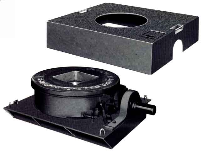
The Oil Rig Online International Drilling Systems Academy Training Specialists 1.2 Rotary Table – Page 2 Rotary Table Checklist • Ensure that safety matting fits around Drawings from the Rotary Table Checklist• Check the condition of the air brake the rotary table. housing. • Measure and record any wear on the• Check the condition of the chain and master bushings and inserts; record the sprockets (maximum chain stretch 3% position of the slips inside the drill pipe as per API RP 7F (2003) section A.3.5). inserts of the master bushings.• Ensure that the electrical cables and • Function-test the manual locking system junction boxes have an EX raating of the rotary table in both directions. required for zone 1. • Review the backlash measurement• Inspect the condition and operation of records. the gearbox; check the oil for possible contamination with water.• Review any oil analysis reports and record the frequency of the oil sampling. Cross-sectional model of rotary table air brake• Function test the rotary table at 120 rpm for 30 minutes in a clockwise rotation; check for heat development.• Function test in an anticlockwise rotation at slow speed (20 RPM) for a short period.• when function testing, allow time for the unit to warm through. Then check the noise and vibration levels. Do not run in reverser for prolonged periods.• Check the condition of the main bearing. Above: Rotary table and master bushing.• Ensure that the DC and/or AC motors draw cooling air form outside the hazard- ous areas and that spark arrestors are fitted on the discharge side of the DC motors or discharge outside the haszard- ous area. Example of wear limit on tapered bowls
The Oil Rig Online International Drilling Systems Academy Training Specialists 1.2 Rotary Table – Page 3Above: Cracks found on the outer sideof the master bushings.
The Oil Rig Online International Drilling Systems Academy Training Specialists 1.2 Rotary Table – Page 4Above: Cracks in the lugs of the split-typemaster bushings.
Above: Rotary table with clearly worn master bushings and master bushing drill pipe inserts.
Left: The pin and the slots of the rotary master bushings need to be measured to ensure that they are within the OEM maximum wear limits.
The Oil Rig Online International Drilling Systems Academy Training Specialists 1.2 Rotary Table – Page 5 Left: Measure the neck of the master bushing inserts to ensure they are still within the OEM maximum wear limits.
The Oil Rig Online International Drilling Systems Academy Training Specialists 1.2 Rotary Table – Page 6Above: Disassembled bearing of the rotary table. Top Right: The bearings and bearing raceNote, the lack of lubricaton and the condition of the for this rotary table are completely destroyed.balls and the bearing race.
The Oil Rig Online International Drilling Systems Academy Training Specialists 1.2 Rotary Table – Page 7 Below: Brake housings are often found badly corroded.
Above: Damaged race and balls Above Right: Air-operated brake of the rotary table within the rotary table bearing. a new housing installed. Due to the brake’s location, corrosion on the brake housings is often severe, and they need regular replacement.
The Oil Rig Online International Drilling Systems Academy Training Specialists 1.2 Rotary Table – Page 8Above: Older totary tables are often driven byDC motors that need spark arrestors fitted to thecooling-air outlets.
Above: Damaged race and balls Above: Rotary table DC motor equipped within the rotary table bearing. new spark arrestors. Note, the purge alarm sensor in between the spark arrestors.
The Oil Rig Online International Drilling Systems Academy Training Specialists 1.2 Rotary Table – Page 9Above Left: New hydraulically-driven rotary tableinstalled and the tracks of the Iron Roughnect on top.
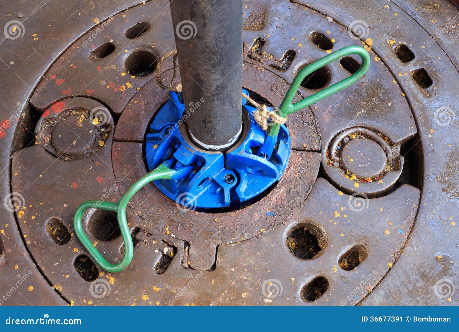
Above: Bowl locks must be in good working order, expecially on rigs which do not use a top drive. The lociks are vedry important, despecially when high-torque levels are encountered due to deviated drilling operationsl
The Oil Rig Online International Drilling Systems Academy Training Specialists 1.2 Rotary Table – Page 10

Cameron rotary tables range from 27 1/2 in to 60 1/2 in and feature a large oil capacity that adds to the unit"s durability. The rotary table includes a forged-steel fabricated housing and a heat-treated forged-steel turntable. Each rotary table is supplied with spiral-bevel, induction-hardened gears and two independent ratchet-type locks, with lever access from the top to lock the table in position.

In this simple diagram of a drilling rig, #20 (in blue) is the rotary table. The drill string, while the rotary table rotates it. (Note: Force is not actually applied from the top (as to push) but rather the weight is at the bottom of the drill string like a pendulum on a string.)
A rotary table is a mechanical device on a drilling rig that provides clockwise (as viewed from above) rotational force to the drill string to facilitate the process of drilling a borehole. Rotary speed is the number of times the rotary table makes one full revolution in one minute (rpm).
The rotary table is also called a turntable. Most rotary tables are chain driven. These chains resemble very large bicycle chains. The chains require constant oiling to prevent burning and seizing. Virtually all rotary tables are equipped with a rotary lock". Engaging the lock can either prevent the rotary from turning in one particular direction, or from turning at all. This is commonly used by crews in lieu of using a second pair of tongs to makeup or break out pipes. The rotary bushings are located at the center of the rotary table. These can generally be removed in two separate pieces to facilitate large items, e.g. drill bits, to pass through the rotary table. The large gap in the center of the rotary bushings is referred to as the "bowl" due to its appearance. The bowl is where the slips are set to hold up the drill string during connections and pipe trips as well as the point the drill string passes through the floor into the wellbore. The rotary bushings connect to the kelly bushings to actually induce the spin required for drilling.
Most recently manufactured rigs no longer feature rotary drives. These newer rigs have opted for top drive technology. In top drive, the drill string is turned by mechanisms located in the top drive that is attached to the blocks. There is no need for the swivel because the top drive does all the necessary actions. The top drive does not eliminate the kelly bar and the kelly bushings.

Rotary drilling uses a sharp, rotating drill bit to dig down through the Earth’s crust. Much like a common hand-held drill, the spinning of the drill bit allows for penetration of even the hardest rock.
The idea of using a rotary drill bit is not new. Archeological records show that as early as 3000 B.C., the Egyptians may have been using a similar technique. Leonardo Di Vinci, as early as 1500, developed a design for a rotary drilling mechanism that bears much resemblance to technology used today. Despite these precursors, rotary drilling did not rise in use or popularity until the early 1900s.
Although rotary drilling techniques had been patented as early as 1833, most of these early attempts at rotary drilling consisted of little more than a mule, attached to a drilling device, walking in a circle. It was the success of the efforts of Anthony Lucas and Patillo Higgins in drilling their 1901 Spindletop well in Texas that catapulted rotary drilling to the forefront of petroleum drilling technology.
While the concept for rotary drilling – using a sharp, spinning drill bit to delve into rock – is quite simple, the actual mechanics of modern rigs are quite complicated. In addition, technology advances so rapidly that new innovations are being introduced constantly.
The basic rotary drilling system consists of four groups of components – the prime movers, hoisting equipment, rotating equipment and circulating equipment – that all combine to make rotary drilling possible.
The prime movers in a rotary drilling rig are those pieces of equipment that provide the power to the entire rig. Steam engines provided the power to the early drill rigs. Gas and diesel engines became the norm after World War II. Recently, while diesel engines still compose the majority of power sources on rotary rigs, other types of engines also are in use; more so in the oil and gas industry than in the water well sector. Natural gas or gasoline engines commonly are used, as are natural gas- or gasoline-powered reciprocating turbines, which generate electricity on-site. The resulting electricity is used to power the rig itself. The energy from these prime movers is used to power the rotary equipment, the hoisting equipment and the circulating equipment, and, on large rigs, may be used as well to provide incidental lighting, water and compression requirements not directly associated with drilling.
The hoisting equipment on a rotary rig consists of the tools used to raise and lower whatever other equipment may go into or come out of the well. The most visible part of the hoisting equipment is the derrick, which serves as a support for the cables (drilling lines) and pulleys (drawworks) that serve to lower or raise the equipment in the well.
For instance, in rotary drilling, the wells are made with long strings of drill pipe extending from the surface down to the drill bit. If a drill bit needs to be changed, either due to wear and tear or a change in the subsurface rock, the whole string of pipe must be raised to the surface.
The rotating equipment on a rotary drilling rig consists of the components that actually serve to rotate the drill bit, which, in turn, sends the hole deeper and deeper into the ground. The rotating equipment consists of a number of different parts, all of which contribute to transferring power from the prime mover to the drill bit itself. The prime mover supplies power to the rotary, which is the device that turns the drill pipe, which, in turn, is attached to the drill bit. A component called the swivel, which is attached to the hoisting equipment, carries the entire weight of the drill string, but allows it to rotate freely.
Below the drill pipe are drill collars, which are heavier, thicker and stronger than normal drill pipe. The drill collars help to add weight to the drill string, right above the bit, to ensure there is enough downward pressure to allow the bit to drill through hard rock. The number and nature of the drill collars on any particular rotary rig can be altered depending on the down-hole conditions experienced while drilling.
The final component of rotary drilling consists of the circulating system. There are a number of main objectives of this system, including cooling and lubricating the drill bit, removing debris and cuttings, and coating the walls of the well with a mud type-cake. The circulating system consists of drilling fluid, which is circulated down through the well hole throughout the drilling process.
The components of the circulating system include drilling fluid pumps, compressors, related plumbing fixtures, and specialty injectors for the addition of additives to the fluid flow stream.
Rotary drilling, as opposed to percussion drilling, cuts by rotating a bit at the bottom of the hole. In addition to rotation, downward pressure must be exerted and continued as the bit cuts it way through the formation.
Part of the art of rotary drilling is to match the bit type and pull-down pressure with the formation, and the use of drilling fluids to maintain circulation to keep the hole clear of cuttings and the bit lubricated and cool. A rotating table turns the drill string via a kelly bar passing through the table and attached to the top joint of the drill string.
When beginning a new hole, and oftentimes during drilling operations, pull-down pressure from the drill rig is applied. This pull-down force is achieved by a screw, cable or chain arrangement, or by hydraulic motors. Hydraulically powered pull-down actions usually are found on more recently manufactured drill rigs, with screw, cable and chain pull-down arrangements more commonly found on older rotary rigs.
The driller controls the pull-down pressure and, thus, the speed of penetration. It must be noted that part of the art of rotary drilling is the matching of pull-down pressure to the formation. Excessive pull-down pressure can damage drill bits, drill pipe and the trueness of the borehole. Thus, applying more pull-down pressure is not always the best drilling practice.
The International School of Well Drilling (ISWD) was established in May 2002 to serve the needs of the water well, environmental and geotechnical sectors of the drilling industry. Since opening, ISWD has trained students both nationally and internationally. These students have included those seeking to enter the drilling industry, and those currently employed at a junior level in the industry, as well as industry regulators and licensed well drillers seeking to further their knowledge.
Since 2005, the ISWD’s focus has shifted to offering training to those already in the water well drilling industry. Continuing education as a requirement for license renewal is required in 27 states. The remaining states are likely to join the majority over time. ISWD is proud to offer continuing education credits for the well drilling industry online.

Drilling involves pipe handling operations in a wellbore, and this in turn requires a false rotary table, a vital cog in the overall success of the operations. At ShalePumps, the need for constant improvement has resulted in an extensive range of precision engineered equipment, of which the false rotary table occupies the limelight.
This hydraulically driven false rotary table is guaranteed to seamlessly engage the tubulars in the wellbore. Pivotal to drilling operations are the sequence of engaging and lowering tubulars into the wellbore. The false rotary table manufactured at our facility is a fine example of harmony between design, materials and precision engineering.
Featuring a mighty load capacity of 1.3 million pounds operating at a maximum speed of 20 rpm, the false rotary table assists the drilling operations in continuous long drawn operations. Pipe handling requires the seamless and sturdy operation of the false rotary table.
ShalePumps, backed by substantive body of experience and knowhow has developed this high performance false rotary table to ably support drilling operations by incorporating a blend of advanced materials and precision engineering. With a guaranteed long life and trouble free run, the ShalePumps false rotary table spins other models out of reckoning.

There are many different ways to drill a domestic water well. One is what we call the “mud rotary” method. Whether or not this is the desired and/or best method for drilling your well is something more fully explained in this brief summary.
One advantage of drilling with compressed air is that it can tell you when you have encountered groundwater and gives you an indication how much water the borehole is producing. When drilling with water using the mud rotary method, the driller must rely on his interpretation of the borehole cuttings and any changes he can observe in the recirculating fluid. Mud rotary drillers can also use borehole geophysical tools to interpret which zones might be productive enough for your water well.
The mud rotary well drilling method is considered a closed-loop system. That is, the mud is cleaned of its cuttings and then is recirculated back down the borehole. Referring to this drilling method as “mud” is a misnomer, but it is one that has stuck with the industry for many years and most people understand what the term actually means.
The water is carefully mixed with a product that should not be called mud because it is a highly refined and formulated clay product—bentonite. It is added, mixed, and carefully monitored throughout the well drilling process.
The purpose of using a bentonite additive to the water is to form a thin film on the walls of the borehole to seal it and prevent water losses while drilling. This film also helps support the borehole wall from sluffing or caving in because of the hydraulic pressure of the bentonite mixture pressing against it. The objective of the fluid mixture is to carry cuttings from the bottom of the borehole up to the surface, where they drop out or are filtered out of the fluid, so it can be pumped back down the borehole again.
When using the mud rotary method, the driller must have a sump, a tank, or a small pond to hold a few thousand gallons of recirculating fluid. If they can’t dig sumps or small ponds, they must have a mud processing piece of equipment that mechanically screens and removes the sands and gravels from the mixture. This device is called a “shale shaker.”
Before the well casing and screens are lowered into the borehole, the recirculating fluid is slowly thinned out by adding fresh water as the fluid no longer needs to support sand and gravel. The driller will typically circulate the drilling from the bottom up the borehole while adding clear water to thin down the viscosity or thickness of the fluid. Once the fluid is sufficiently thinned, the casing and screens are installed and the annular space is gravel packed.
Gravel pack installed between the borehole walls and the outside of the well casing acts like a filter to keep sand out and maintain the borehole walls over time. During gravel packing of the well, the thin layer of bentonite clay that kept the borehole wall from leaking drilling fluid water out of the recirculating system now keeps the formation water from entering the well.
Mud rotary well drillers for decades have found ways to make this particular system work to drill and construct domestic water wells. In some areas, it’s the ideal method to use because of the geologic formations there, while other areas of the country favor air rotary methods.
Some drilling rigs are equipped to drill using either method, so the contractor must make the decision as to which method works best in your area, for your well, and at your point in time.
To learn more about the difference between mud rotary drilling and air rotary drilling, click the video below. The video is part of our “NGWA: Industry Connected” YouTube series:
Gary Hix is a Registered Professional Geologist in Arizona, specializing in hydrogeology. He was the 2019 William A. McEllhiney Distinguished Lecturer for The Groundwater Foundation. He is a former licensed water well drilling contractor and remains actively involved in the National Ground Water Association and Arizona Water Well Association.

Explore the various drilling rig parts rotary table products available for wholesale at Alibaba.com. Get a drilling rig parts rotary table for drilling water wells, water exploration holes, geological exploration, coal mines, and other kinds of mining. Some drilling rig parts rotary table options use caterpillar tread to move. Others use rubber tires, while others require a separate means of transport. Caterpillar tread propulsion can climb up to 25 degrees inclination. Some products in the range are capable of drilling over 200 meters, while others are only used for open-pit mining with depths of around 3 meters. Drilling can be done vertically downwards, horizontally, or in a slanting direction. Drilling speed depends on the power of the machine and the general hardness of the surface. The hole diameter can vary from 90mm to 200mm.
drilling rig parts rotary table options also include an air compressor, a mud pump, drilling rods of various sizes, connectors, and a drilling tower. Drilling is done using drill bits of various shapes, sizes, and compositions. You can choose between diamond bits, alloy ring-shaped bits, 3-wing alloy bits, PDC bits, and hammer bits. Each drill bit uses different drilling methods, including rotary, percussion, blast hole, and core drilling.
Smaller products have a lifting power of around 25 kilonewtons and weigh about 2,500kgs. They’re ideal for small-scale drillings such as farms and homes. Larger ones are faster with more power, making them ideal for commercial use. Browse through Alibaba.com and find a drilling rig parts rotary table that’s ideal for your work scope. Buy mine drilling rigs for your wholesale business at competitive prices. Chinese wholesalers provide you with customization options and great after-sales services.

One or more valves installed at the wellhead to prevent the escape of pressure either in the annular space between the casing and the drill pipe or in open hole (for example, hole with no drill pipe) during drilling or completion operations. See annular blowout preventer and ram blowout preventer.†
The arrangement of piping and special valves, called chokes, through which drilling mud is circulated when the blowout preventers are closed to control the pressures encountered during a kick.†
A centrifugal device for removing sand from drilling fluid to prevent abrasion of the pumps. It may be operated mechanically or by a fast-moving stream of fluid inside a special cone-shaped vessel, in which case it is sometimes called a hydrocyclone.†
A centrifugal device, similar to a desander, used to remove very fine particles, or silt, from drilling fluid. This keeps the amount of solids in the fluid to the lowest possible level.†
The hoisting mechanism on a drilling rig. It is essentially a large winch that spools off or takes in the drilling line and thus raises or lowers the drill stem and bit.†
The cutting or boring element used in drilling oil and gas wells. Most bits used in rotary drilling are roller-cone bits. The bit consists of the cutting elements and the circulating element. The circulating element permits the passage of drilling fluid and uses the hydraulic force of the fluid stream to improve drilling rates.†
The heavy seamless tubing used to rotate the bit and circulate the drilling fluid. Joints of pipe 30 feet long are coupled together with tool joints.†
A wire rope hoisting line, reeved on sheaves of the crown block and traveling block (in effect a block and tackle). Its primary purpose is to hoist or lower drill pipe or casing from or into a well. Also, a wire rope used to support the drilling tools.†
The heavy square or hexagonal steel member suspended from the swivel through the rotary table. It is connected to the topmost joint of drill pipe to turn the drill stem as the rotary table turns.†
A device fitted to the rotary table through which the kelly passes. It is the means by which the torque of the rotary table is transmitted to the kelly and to the drill stem. Also called the drive bushing.†
A portable derrick capable of being erected as a unit, as distinguished from a standard derrick, which cannot be raised to a working position as a unit.†
A series of open tanks, usually made of steel plates, through which the drilling mud is cycled to allow sand and sediments to settle out. Additives are mixed with the mud in the pit, and the fluid is temporarily stored there before being pumped back into the well. Mud pit compartments are also called shaker pits, settling pits, and suction pits, depending on their main purpose.†
A trough or pipe, placed between the surface connections at the well bore and the shale shaker. Drilling mud flows through it upon its return to the surface from the hole.†
A diesel, Liquefied Petroleum Gas (LPG), natural gas, or gasoline engine, along with a mechanical transmission and generator for producing power for the drilling rig. Newer rigs use electric generators to power electric motors on the other parts of the rig.†
A mud pit in which a supply of drilling fluid has been stored. Also, a waste pit, usually an excavated, earthen-walled pit. It may be lined with plastic to prevent soil contamination.†
The hose on a rotary drilling rig that conducts the drilling fluid from the mud pump and standpipe to the swivel and kelly; also called the mud hose or the kelly hose.†
The principal component of a rotary, or rotary machine, used to turn the drill stem and support the drilling assembly. It has a beveled gear arrangement to create the rotational motion and an opening into which bushings are fitted to drive and support the drilling assembly.
A series of trays with sieves or screens that vibrate to remove cuttings from circulating fluid in rotary drilling operations. The size of the openings in the sieve is selected to match the size of the solids in the drilling fluid and the anticipated size of cuttings. Also called a shaker.†
Wedge-shaped pieces of metal with teeth or other gripping elements that are used to prevent pipe from slipping down into the hole or to hold pipe in place. Rotary slips fit around the drill pipe and wedge against the master bushing to support the pipe. Power slips are pneumatically or hydraulically actuated devices that allow the crew to dispense with the manual handling of slips when making a connection. Packers and other down hole equipment are secured in position by slips that engage the pipe by action directed at the surface.†
A relatively short length of chain attached to the tong pull chain on the manual tongs used to make up drill pipe. The spinning chain is attached to the pull chain so that a crew member can wrap the spinning chain several times around the tool joint box of a joint of drill pipe suspended in the rotary table. After crew members stab the pin of another tool joint into the box end, one of them then grasps the end of the spinning chain and with a rapid upward motion of the wrist "throws the spinning chain"-that is, causes it to unwrap from the box and coil upward onto the body of the joint stabbed into the box. The driller then actuates the makeup cathead to pull the chain off of the pipe body, which causes the pipe to spin and thus the pin threads to spin into the box.†
A vertical pipe rising along the side of the derrick or mast. It joins the discharge line leading from the mud pump to the rotary hose and through which mud is pumped going into the hole.†
A rotary tool that is hung from the rotary hook and traveling block to suspend and permit free rotation of the drill stem. It also provides a connection for the rotary hose and a passageway for the flow of drilling fluid into the drill stem.†
The large wrenches used for turning when making up or breaking out drill pipe, casing, tubing, or other pipe; variously called casing tongs, rotary tongs, and so forth according to the specific use. Power tongs are pneumatically or hydraulically operated tools that spin the pipe up and, in some instances, apply the final makeup torque.†
The top drive rotates the drill string end bit without the use of a kelly and rotary table. The top drive is operated from a control console on the rig floor.†

The present invention relates in general to the art of drilling oil and gas wells and, more particularly, to the measurement of rotary torque and RPM for oil and gas drilling rigs.
In the drilling of oil and gas wells with rotary rigs, and, in particular, the drilling of deep wells, the drill pipe is subjected to considerable stress. The stress is imposed by the weight of the drill string, by the resistance of the strata to the rotation of the drill pipe and to the cutting action of the drill bit in the different strata. Care must be taken to control the amount of torque imposed on the drill string, otherwise twist-offs may occur which would result in expensive fishing jobs to retrieve the last portion of the drill string.
The measurement of rotary torque is used to observe pipe sticking, indicate bit wear and optimize drilling. The counting of total revolutions of the drill string can give wear-life data to help prevent failure while drilling. RPM, used with rotary torque, weight on bit and rate of penetration, can be used to calculate factors that give valuable drilling data. The present invention provides a system for the transmission of rotary torque and real time revolutions from the rotary table/Kelly combination of an oilfield or other rotary drilling rig. Real time revolutions allow the RPM to be calculated.
The prior art measurement of rotary torque and revolving speed utilizes two, usually separate, transducer systems. Rotations are sensed by proximity switches which are closed each revolution. This method is commonly used, however, the switches often get in the way of the driller. Another commonly used method is to use a take-off point in the rotary chain drive and an electrical tachometer-generator. This method has the drawbacks of having to scale the output voltage and/or frequency in order to determine true revolutions. Either method is commonly used by wiring the transducer to the readout mechanism. Rotary torque is often measured by means of tension measurement in the rotary drive chain, accessible only from beneath the rig floor and rotary table.
In U.S. Pat. No. 3,664,184 to Norman D. Dyer, patented May 23, 1972, a rotary torque indicator for well drilling apparatus is shown and described as follows. The device is used to indicate torque applied by the rotary table to the drill string during drilling of oil and gas wells. An intermediate adapter between the Kelly bushing and the rotary table in one embodiment has two parts. The lower part of the adapter includes a standard male square drive that fits into the square drive of the rotary table, and is thus rotated by the rotary table. The upper part of the adapter includes a female square drive arranged to receive the male square drive on the Kelly. The Kelly transmits torque from the adapter assembly to the drill pipe. The upper part is connected to the lower part by either hydraulic cylinders or by linkage with strain gauge. The upper part rotates with the lower part, but is moveable relative thereto to indicate relative torque between the upper and lower parts. An R.F. transmitter connected to the hydraulic cylinder or strain gauge provides a torque signal to a remote R.F. receiver. An alternative embodiment has a unitized adapter assembly. Still another alternative embodiment uses a torque sensor and R.F. transmitter directly on the Kelly drive bushing without utilization of an intermediate bushing.
In U.S. Pat. No. 3,691,825 to Norman D. Dyer, patented Sept. 19, 1972, a rotary torque indicator for well drilling apparatus is shown and described as follows. This device is used to indicate torque applied by the rotary table to the drill string during drilling of oil and gas wells. An intermediate adapter between the Kelly bushing and the rotary table in one embodiment has two parts. The lower part of the adapter includes a standard male square drive that fits into the square drive of the rotary table, and is thus rotated by the rotary table. The upper part of the adapter includes a female square drive arranged to receive the male square drive on the Kelly. The Kelly transmits torque from the adapter assembly to the drill pipe. The upper part is connected to the lower part by either hydraulic cylinders or by linkage with a strain gauge. The upper part rotates with the lower part, but is moveable relative thereto to indicate relative torque between the upper and lower parts. An R.F. transmitter connected to the hydraulic cylinder or strain gauge provides a torque signal to a remote R.F. receiver. An alternative embodiment has a unitized adapter assembly. Still another alternative embodiment uses a torque sensor and R.F. transmitter directly on the Kelly drive bushing without utilization of an intermediate bushing.
The present invention provides a system for measuring the rotary torque and RPM of a rotary drill string. An intermediate adapter is positioned between the Kelly and the rotary table. A strain gauge is attached to the intermediate adapter to measure torsional deformation and provide an indication of rotary torque. Transmission of torque data is accomplished by radio frequency transmission utilizing a transmitter on the intermediate adapter. A receiver is mounted to the side of the drill rig floor to receive and demodulate the torque signal. The intermediate adapter is rotating at the same rate as the drill string. Detection of revolutions of the drill string is accomplished at the edge of the drill rig platform or elsewhere with a stationary sensor which doubles as the torque receiver. A highly directional torque transmitter antenna mounted on the adapter is used with the major lobe parallel to the rig floor and perpendicular to the drill pipe. By detecting the envelope of the radio frequency field strength, each rotation is marked by a peak. This enables continuous torque and RPM monitoring. The foregoing and other features and advantages of the present invention will become apparent from a consideration of the following detailed description of the invention when taken in conjunction with the accompanying drawings.
Referring now to the drawings and, in particular, to FIG. 1, an embodiment of the present invention is illustrated in conjunction with an oil well drilling rig 10 and a rotary drill string 11 used in an oil well drilling operation. A well bore 12 is shown having a casing 13. The rotary drill string 11 is provided with a drill bit 14 at its lower end. The drill string 11 is rotated by a rotary table 15 mounted in the derrick 16. Drilling mud is pumped from a mud pit 17 through line 18 by pump 19. The mud is pumped into the drill string 11 and is discharged out of the bit 14 into the well bore 12. The mud continues upward in the well bore 12 and is returned from the top of the casing 13 by a mud flowline 20 to the mud pit 17. An openable and closeable blowout preventer or rotary drill head of any suitable conventional type is provided at the upper end of the casing 13.
The drill string 11 is attached to the lower end of the drive Kelly 21. An intermediate adapter 22 is positioned between the Kelly 21 and the rotary table 15. Enlarged views of the intermediate adapter 22 are shown in FIGS. 2 and 3. The adapter 22 rotates with the drill string/Kelly combination and transmits all of the torque from the rotary table 15 to the Kelly 21. The mechanical portion is a one-piece adapter with one end 23 that fits into the square rotary table drive bushing. The other end 24 accepts the square shoulder of the Kelly drive. Between the two ends is a tubular section 25 that allows the Kelly 21 to pass through. The material and thickness of this tubular section 25 must be chosen so that the torque range transmitted through the adapter 22 is sufficient to achieve a measurable elastic strain deformation yet be totally safe from structural failure. This type of Kelly adapter is described in U.S. Pat. Nos. 3,664,184 and 3,691,825 by Norman Dyer.
For a one-piece adapter, a strain gauge torsional sensor is used. A two-piece unit engaged to compress a load cell may also be used to indicate torque, as described in the Dyer patents. Since all torque is transmitted through the adapter 22 calibration is independent of the rig it is installed in. This is an advantage over other types of sensors. Transmission of signals is accomplished by radio frequency telemetry, allowing maximum freedom from physical interconnections. Prior art methods of RPM and torque measurement require sensors mounted in physically inconvenient locations, i.e. under the drilling rig floor, and required semi-permanent wiring or hydraulic connections. Calibration of the prior art sensors is required and must be done on location where standards to calibrate against are frequently unavailable. The present invention allows easy installation at any time and is calibrated independently of the installation, so that calibration to a standard for torque is possible, and output in true revolutions can be determined without having to obtain ratios and scale factors as must now be done for prior art tachometer-generators commonly used.
The transmission of the torque and RPM information from the adapter 22 to a receiver 27 is illustrated in FIG. 4. A top view of the floor of the drilling rig 16 is illustrated. The analog strain value is converted to a frequency and the frequency is used to f-m modulate the carrier frequency. The radio frequency chosen is based on interference, regulations and acceptable antenna dimensions. The transmitter may be low powered since the usual distance to be transmitted is less than 100 feet. The receiver 27 mounted to the side of the drill rig floor will receive and demodulate the torque and RPM signal. Since the adapter 22 is rotating at the same rate as the drill string and rotary table, simultaneous torque detection and revolutions of the rotary table are obtained. The revolutions may be detected at the edge of the drill rig platform with a stationary sensor which doubles as the torque receiver. A highly directional torque transmitter antenna is mounted on the adapter with the major lobe lying parallel to the rig floor and perpendicular to the drill pipe. By detecting the envelope of the R.F. (radio frequency) field strength, each rotation is marked by a peak. This enables continuous torque and RPM monitoring.
It would also be possible to provide an antenna system mounted in the Kelly so that its phase angle would be constantly changing relative to the receiver. The receiver would monitor the phase cancellations and reinforcements and determine the occurrence of each revolution. It is also possible to monitor revolutions only, by not modulating the R.F. signal from the Kelly assembly. In this case, the Kelly adapter is not necessary and the electronics (transmitter and antenna) may be mounted directly to the Kelly or Kelly bushing. From indications of each rotation, conventional rate meters may be used to indicate rotary rate in RPM. Such meters may be a SWACO Div. of Dresser Industries Combination Pump Stroke Rate Meter/Counter, which has the capability of determining RPM of an input signal closure rate.
2.The drilling rig is a bulk rotary table drill, which is mainly used for middle Quaternary, fine grained strata and soft rock layers. The main uses are: the hydrogeological conditions at the bottom of the exploration and survey; the drilling and drilling for the agricultural irrigation, the industrial water use, the underground tunnel ventilation, the bridge and other engineering drilling.
3. When drilling rigs, mud flushing fluid (positive circulation) and rotary table are used to drive the drilling tools to rotate. Winch system decompression drilling, lifting drilling, underground pipe, impact sampling, stand rig etc..


 8613371530291