
arduino rotary table price

Sherline’s CNC driver box comes equipped with an A-axis output cable ready to drive a 4th rotary axis. This rotary table is all you need to turn your Sherline CNC mill into a 4-axis machine. Just plug the A-axis cable from the external driver box or the built-in driver box in your Sherline computer into the matching plug on the stepper motor. The EMC2 software is already set up to handle G-code for the A-axis, and numbers entered after the letter “A” in your code are interpreted in degrees.
The same end result can be obtained by ordering a CNC ready rotary table and a stepper motor and attaching the motor, but this single part number does the same thing, making it easier to order and saving you the trouble of installing the motor on the rotary table.
This project is an upgrade to the electronic rotary table we built in a previous project. That project covers the electronics and software more in depth.

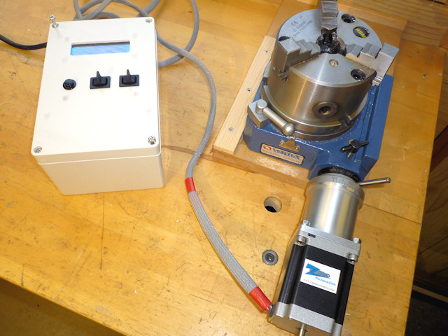
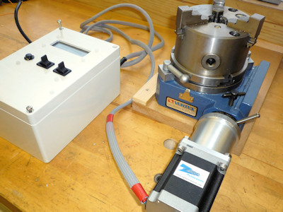
I recently read an article in Model Engineers Workshop Magazine (December 2016 issue 249) for adding a stepper motor drive to a rotary table. I don′t use my small Vertex rotary table very often but I thought this might be a useful project to learn a little about stepper motors and digital control of machinery. The article by Carl Wilson describes how to use an Arduino micro-controller to control the rotary division process. Much of the coding is contained in another article in Digital Machinist by Gary Liming. So no original thinking by me here, just a rehash of other engineers good work. All the links and useful information can be found in the Glossary at the end.
Prepping the table can be as simple as doing nothing, a complete strip down and re-build with thrust washers and the like or somewhere in between. There are a few articles on the web giving details (see glossary). Software setup and programming the Arduino is the quickest part and if you use Gary Liming′s software without alteration, the programming takes just a few seconds. Assembling the electronics is mainly about fitting the bits into the box and requires a bit of inginuity to fix things in place. The boards are fairly flimsy and things, like the display, tend not to be square or flat, I found.
The stepper motor mounting I made from three parts and assembled with Loctite and screws. I have no doubt there are other ways of making this or a suitable motor mount could be found ready made and adapted to fit the table. You will probably want to test things as you you go along rather than leave everything to the end. I discovered I had a faulty motor driver, easier to deal with whilst still uncased. I don′t think it makes makes any difference which order things are done.
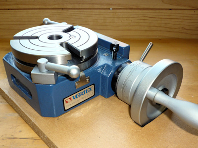
This is covered elsewhere on the web in some detail so I have just made a few notes that may be of interest. Dismantling the table is quite straightforward, just look for allen headed grub screws at the bottom of deep holes. The notes refer to my 4" Vertex table.
Start off by removing the handle, the table locking clamps and the worm engagement lock. The handle is just one screw but watch out for the shaft key which is small and easily lost. Photo (2) shows the board I made to store the table with a cutout for the handle. The stepper motor will also need a similar storage solution. I used pliers and some cardboard to protect the finish to unscrew the table clamp handles. Remove the engagement lever and collar, two grub screws and it slides off, this is the part that the motor connector will attach to, it has three ready tapped holes for when used with division plates.
Remove the cam shaft securing and adjusting collar (4), four cap screws. Remove the grub screw that sets the worm engagement depth, found at the bottom of a deep hole (5). The worm shaft and cam bearing can now be removed as one unit, rotate the table and it will push the spindle out.
Turn the table upside down and remove the table bearing and adjustment plate (6), four cap screws. The table can now be removed, mine was pretty clean (7) not having been used much, there wasn′t even that much grease. Now that everything is apart it can all be cleaned re-greased and re-assembled. The worm drive shaft can be slid out of the cam adjuster by removing the collar, it is a ground shaft with an oilway and a very good fit in the cam adjuster.
Other than adjustment to remove backlash I didn′t make any changes to my rotary table, it was in fact pretty good before I started. If you have an older well used table it may take a bit more cleaning to remove old grease and any swarf that may have found it′s way inside.
Other parts worth note are the cam shaft retainer / bearing (4) and the table retainer / bearing (6). These both feature four cap screws which bolt the item in place and four grub screws which act as jack-screws to prevent clamping the rotating part. When reassembling it is worth adjusting these carefully to limit the table lifting whilst still turning freely and likewise to prevent the cam shaft moving in and out. I noticed with the table bearing / retainer that there was a noticeable stiff spot so it is worth rotating the table through a full 360° whilst adjusting. The cam shaft could be locked in place if you think there is no need to disengage the worm gear. Last bit is to set the worm engagement, this is controlled by a grub screw at the side (5) which engages with a slot in the cam shaft to prevent rotation. If you undo the grub screw and fully engage the worm it will be very difficult to turn, tighten the grub screw just enough so that the worm turns easily with a minimum of backlash.
Not much to this really but first you will need to go to the Arduino website and download the Integrated Development Environment (IDE) software. This is basically a fairly lightweight program that runs on your PC (Windows, Mac or Linux) and allows you to edit programs (sketches in Arduino speak) and upload to the Arduino board. You will also need to download Gary Liming′s software. Once the software is downloaded installation is straightforward. The Arduino IDE is self-installing from an exe file in Windows. Gary Liming′s programs come as a zip file which needs un-zipping to a folder. Once unzipped, double click on the "Stepindex23.ino" file and it will start the Arduino IDE and load the program.
All being well you should now have a screen like something like those above. Click on the image to read the text. Affix the LCD shield to the Uno making sure that all the pins are in the right places and none of the connectors is bent. Plug the Uno into the PC using a USB cable, often supplied with the board. The Uno will be powered by the USB connection. First thing to do is go to the "Tools" menu (10) and set the type of board. All being well the software should then report that it is talking to the Uno, bottom right of the IDE, something like "Arduino/Genuino UNO on COM4". You should also be able to click on the "Port" section of the menu to assign a COM port. If this isn′t working and the Port section is greyed out it may be driver related.
Arduino micro-controllers are mainly programmed using the C++ programming language or at least a subset of C++, so the programs are fairly understandable for basic editing. The first few lines of the program (11) are used to set parameters used later. These can be adjusted now, the program is well commented, or left until later when everything is assembled. You may wish to alter gear ratios or even remove some items. There is more help in the readme files that come in the program zip-file. If you are a C++ programmer the world is your oyster, the menu items can be moved around or even removed if you don′t need a particular function. You may wish to experiment with some of the delay timings to help de-bounce the keys but this is probably better done during final testing.
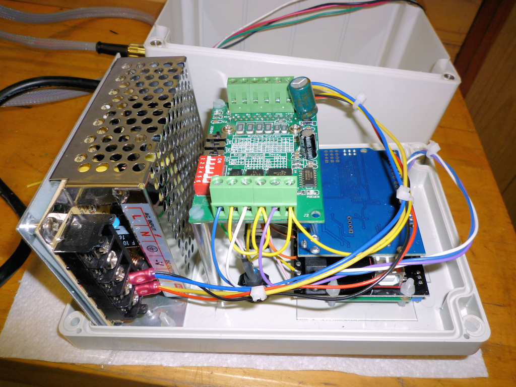
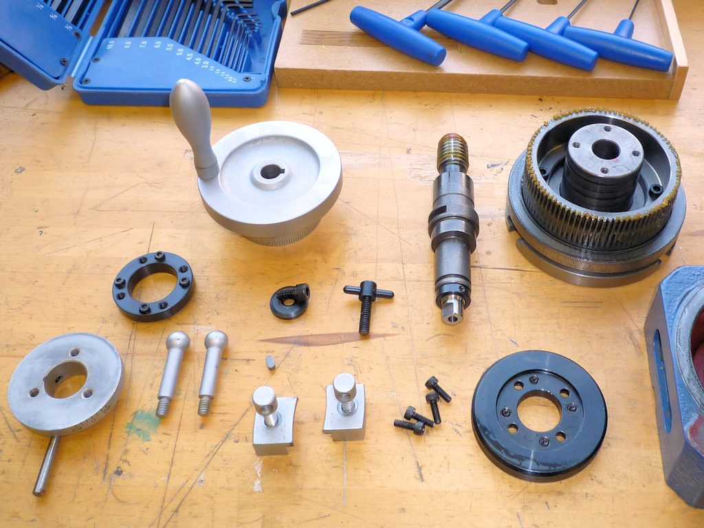
The parts are shown (12) above and are the Arduino Uno, the LCD shield, the cable gland, TB6560 stepper driver, switches, plug, socket and power supply. The circuit boards are all pretty flimsy and the mounting holes are very close to the edges. The LCD shield has a seperate smaller board for the LCD soldered on top and the two boards were not particularly parallel. There is also a multi-turn variable resistor on the board which cunningly sticks up higher than the LCD face. If you are adept with a soldering iron it can be re-positioned on the other side of the PCB. I solved the non-flush pot problem by using a 1.5mm clear polycarbonate sheet between the box lid and LCD with a small cutout for the variable resistor.
I fitted as much as I could to the box lid, only the mains in and stepper out are fitted to the box. The display needs a cutout in the lid as do the three switches and a number of 3mm holes for various mounting screws. Once I had worked out the position of all the bits I marked the inside of the box lid for the position of the LCD and switch cutouts. I set this up on the mill and used a 5mm slot drill to remove the cutouts, the ABS machines very easily. I fixed the lid to an off-cut of MDF with woodscrews through the mounting holes, I also used double sided tape to make sure nothing moved. A couple of T-nuts and studs fixed the MDF to the mill table (13). With hindsight the double sided tape was overkill, it took me longer to get it off the lid than it did to do the machining. The corners of the switch cutouts I filed square, I drilled the various mounting bolt holes by hand as I did for the other round holes opening them up as necessary with a taper reamer and file.
I made the two flat plates and then fitted the motor, flexible coupling and rotary table together to measure the shortest length of tube that would work. The dimensions for the motor mounting plate were copied from the motor spec sheet.
I used another bit of 3" x ¼" bar to turn the plate that bolts to the rotary table. I drilled a 10mm hole in the centre of the plate and used a length of studding to hold it (22). The studding has two nuts locked to it which fit against the back of the chuck jaws and a nut and washer clamp the plate against the front of the jaws, there is a centre in the outboard end of the studding for support. I used a trepanning tool to remove the corners and then turned the O.D. to to size.
When the R.T. mounting plate is the correct diameter add a step 3mm deep with 38.1mm diameter to create a short spigot to fit the tube bore. Remove from the mandrel (studding) and mount holding the just turned spigot (23), bore out the centre hole to 21mm to fit the R.T. collar. To finish this part it need the three mounting holes drilled to match the table. I clamped the table index ring to the plate, they should be the same diameter, then spotted through with a drill that just cleared the threads in the index ring. Unclamp and drill the holes 5mm, there is no other alignment so keep the holes small, don"t use an M5 clearance drill.
The three parts are "glued" together, I used Loctite 603 which is a high strength oil tolerant retainer. Check alignment before joining, it will depend on the orientation of the holes in the index collar on the R.T. probably easier to join the tube to the table end first and then bolt it in place. The motor mount can then be aligned so that it is square when in use. I had an interesting experience when I first tried assembly. applied the Loctite placed suitable weight on top and left overnight. The following day removed the weight picked it up and it came apart. Apparently Loctite "goes off" still mine was a few years old! If you want to add screws it is probably easier to do this after assembly, I used 3 M3 C/S screws in each end, a bit belt and braces as either screws or adhesive alone will probably do the job.
Not much to this really, first bolt the connector to the rotary table. Slide in the flexible coupling and tighten onto the table drive, I aligned it so that the grub screw would tighten into the keyway. Fit the motor using four M5 capscews, nuts and shakeproof washers. Tighten the coupling onto the motor shaft and thats the mechanical bit done.
To test I went through each menu item in turn and made sure it did what it was supposed to. I discovered that clockwise and anti-clockwise were reversed but this can be adjusted in the software. I also discovered that I had wired one switch back to front and needed to reverse the leads fortunately just swapping a couple of push on connectors. Found that the motor vibrated rather heavily, haven′t got to the cause of that yet. I also set the table to zero on it′s scale and checked that the angle turned matched what the display said for a full 360° - it did.
With a bit of work on the software, to slow the motor down, I don′t see why the table could not be operated under power, to mill say a semi-circular slot. WIll also need a bit of work on the switch de-bounce software for this to ensure reliability, as it is it is easy to double press keys. Nice little project a good introduction to both the Arduino and to stepper motors neither of which I had used before.
As I had to take everything apart I added a reset button (29) by soldering leads to the back of the shield button in the same way as for the other buttons. Caused me some aggravation as the first button I found in my "bits that will be useful one day box" remained steadfastly open-circuit when pressed, still it was probably 30 years old! Last but not least a short video (30) which shows the table spinning quietly in run mode and then vibrating in step and angle mode. It makes me think this might be software generated as that is the only difference between the modes.
Model Engineers Workshop Forum- thread discussing the original magazine article and various points arising including some useful information about variations in the Arduino hardware, particularly the LCD shield.
Gary Liming′s Website- describes the making of the original step-indexer which could be used in place of a rotary table and outlines the software in a bit more detail.
Arduino Home Page- has all the information about the Arduino project. You can download the IDE (Integrated Development Environment) from here which you will need to program the micro-controller board.
CH340G driver- Some boards use the CH340G USB/serial chip as a cheaper alternative to the FTDI chip, this is the driver download link. The FTDI standard driver is installed when you setup the Arduino IDE.
Model Engine Maker Forum- thread covering the preparation of a Vertex rotary table ready for automation. This was done by John "Bogstandard" Moore in readiness for the Division Master system but the mechanics are the same.
The list above is for the major parts required for the project. The suppliers are those I used and the prices were correct in January 2017. (Please note the links to some of these items seem to change weekly, apologies if they don′t work) I make no particular recommendation as to the suppliers it is just where I found the bits needed, it is likely that better/cheaper/different parts are available from myriad locations on the web. In addition to the bits listed you will need - hook-up wire, solder, nuts, bolts, spacers, cable ties, crimp connectors and sleeving. Please note that the above table doesn"t display well on a small screen, try rotating to landscape to view!
Many of the links in the Glossary and particularly the Parts List table have gone missing over time so I have tried to update them with currently available parts and information. In fact none of the parts are particularly critical and a bit of web searching will find suitable replacements. The Model Engineer Forum link is still active and one of the later additions is the replacement of the switches with a cheaply available numeric keypad. I haven"t carried out this mod but it looks quite interesting.

Along 3 years I have been trying several leg mechanism, at first I decided to do a simple desing with tibial motor where placed on femur joint.This design had several problems, like it wasn"t very robust and the most importat is that having the motor (with big mass) that far from the rotating axis, caused that in some movements it generate unwanted dynamics to the robot body, making controlability worse.New version have both motors of femur/tibial limb at coxa frame, this ends with a very simple setup and at the same time, the heaviest masses of the mechanism are centered to the rotating axis of coxa limb, so even though the leg do fast movements, inertias won"t be strong enough to affect the hole robot mass, achieving more agility.Inverse Kinematics of the mechanismAfter building it I notice that this mechanism was very special for another reason, at the domain the leg normally moves, it acts as a diferential mecanism, this means that torque is almost all the time shared between both motor of the longer limbs. That was an improvent since with the old mechanism tibial motor had to hold most of the weight and it was more forced than the one for femur.To visualize this, for the same movement, we can see how tibial motor must travel more arc of angel that the one on the new version.In order to solve this mechanism, just some trigonometry is needed. Combining both cosine and sine laws, we can obtain desired angle (the one between femur and tibia) with respect to the angle the motor must achieve.Observing these equations, with can notice that this angle (the one between femur and tibia) depends on both servos angles, which means both motors are contributing to the movement of the tibia.Calibration of servosAnother useful thing to do if we want to control servo precisely is to print a calibration tool for our set up. As shown in the image below, in order to know where real angles are located, angle protactor is placer just in the origin of the rotating joint, and choosing 2 know angles we can match PWM signal to the real angles we want to manipulate simply doing a lineal relation between angles and PWM pulse length.Then a simple program in the serial console can be wrtten to let the user move the motor to the desired angle. This way the calibration process is only about placing motor at certain position and everything is done and we won"t need to manually introduce random values that can be a very tedious task.With this I have achieved very good calibrations on motors, which cause the robot to be very simetrial making the hole system more predictable. Also the calibration procedure now is very easy to do, as all calculations are done automatically. Check Section 1 for the example code for calibration.More about this can be seen in the video below, where all the building process is shown as well as the new leg in action.SECTION 1:In the example code below, you can see how calibration protocol works, it is just a function called calibrationSecuence() which do all the work until calibration is finished. So you only need to call it one time to enter calibration loop, for example by sending a "c" character thought the serial console.Also some useful function are used, like moving motor directly with analogWrite functions which all the calculations involved, this is a good point since no interrupts are used.This code also have the feature to calibrate the potentiometer coming from each motor.#define MAX_PULSE 2500 #define MIN_PULSE 560 /*---------------SERVO PIN DEFINITION------------------------*/ int m1 = 6;//FR int m2 = 5; int m3 = 4; int m4 = 28;//FL int m5 = 29; int m6 = 36; int m7 = 3;//BR int m8 = 2; int m9 = 1; int m10 = 7;//BL int m11 = 24; int m12 = 25; int m13 = 0;//BODY /*----------------- CALIBRATION PARAMETERS OF EACH SERVO -----------------*/ double lowLim[13] = {50, 30, 30, 50, 30, 30, 50, 30, 30, 50, 30, 30, 70}; double highLim[13] = {130, 150, 150, 130, 150, 150, 130, 150, 150, 130, 150, 150, 110}; double a[13] = { -1.08333, -1.06667, -1.07778, //FR -1.03333, 0.97778, 1.01111, //FL 1.03333, 1.05556, 1.07778, //BR 1.07500, -1.07778, -1.00000, //BL 1.06250 }; double b[13] = {179.0, 192.0, 194.5, //FR 193.0, 5.5, -7.5, //FL 7.0, -17.0, -16.0, //BR -13.5, 191.5, 157.0, //BL -0.875 }; double ae[13] = {0.20292, 0.20317, 0.19904 , 0.21256, -0.22492, -0.21321, -0.21047, -0.20355, -0.20095, -0.20265, 0.19904, 0.20337, -0.20226 }; double be[13] = { -18.59717, -5.70512, -2.51697, -5.75856, 197.29411, 202.72169, 185.96931, 204.11902, 199.38663, 197.89534, -5.33768, -32.23424, 187.48058 }; /*--------Corresponding angles you want to meassure at in your system-----------*/ double x1[13] = {120, 135, 90, 60, 135 , 90, 120, 135, 90, 60, 135, 90, 110}; //this will be the first angle you will meassure double x2[13] = {60, 90, 135, 120, 90, 135, 60, 90, 135, 120, 90, 135, 70};//this will be the second angle you will meassure for calibration /*--------You can define a motor tag for each servo--------*/ String motorTag[13] = {"FR coxa", "FR femur", "FR tibia", "FL coxa", "FL femur", "FL tibia", "BR coxa", "BR femur", "BR tibia", "BL coxa", "BL femur", "BL tibia", "Body angle" }; double ang1[13] = {0, 0, 0, 0, 0, 0, 0, 0, 0, 0, 0, 0, 0}; double ang2[13] = {0, 0, 0, 0, 0, 0, 0, 0, 0, 0, 0, 0, 0}; float xi[500]; float yi[500]; float fineAngle; float fineL; float fineH; int motorPin; int motor = 0; float calibrationAngle; float res = 1.0; float ares = 0.5; float bres = 1.0; float cres = 4.0; float rawAngle; float orawAngle; char cm; char answer; bool interp = false; bool question = true; bool swing = false; int i; double eang; int freq = 100; // PWM frecuency can be choosen here. void connectServos() { analogWriteFrequency(m1, freq); //FR coxa digitalWrite(m1, LOW); pinMode(m1, OUTPUT); analogWriteFrequency(m2, freq); //femur digitalWrite(m2, LOW); pinMode(m2, OUTPUT); analogWriteFrequency(m3, freq); //tibia digitalWrite(m3, LOW); pinMode(m3, OUTPUT); analogWriteFrequency(m4, freq); //FL coxa digitalWrite(m4, LOW); pinMode(m4, OUTPUT); analogWriteFrequency(m5, freq); //femur digitalWrite(m5, LOW); pinMode(m5, OUTPUT); analogWriteFrequency(m6, freq); //tibia digitalWrite(m6, LOW); pinMode(m6, OUTPUT); analogWriteFrequency(m7, freq); //FR coxa digitalWrite(m7, LOW); pinMode(m7, OUTPUT); analogWriteFrequency(m8, freq); //femur digitalWrite(m8, LOW); pinMode(m8, OUTPUT); analogWriteFrequency(m9, freq); //tibia digitalWrite(m9, LOW); pinMode(m9, OUTPUT); analogWriteFrequency(m10, freq); //FR coxa digitalWrite(m10, LOW); pinMode(m10, OUTPUT); analogWriteFrequency(m11, freq); //femur digitalWrite(m11, LOW); pinMode(m11, OUTPUT); analogWriteFrequency(m12, freq); //tibia digitalWrite(m12, LOW); pinMode(m12, OUTPUT); analogWriteFrequency(m13, freq); //body digitalWrite(m13, LOW); pinMode(m13, OUTPUT); } void servoWrite(int pin , double angle) { float T = 1000000.0f / freq; float usec = float(MAX_PULSE - MIN_PULSE) * (angle / 180.0) + (float)MIN_PULSE; uint32_t duty = int(usec / T * 4096.0f); analogWrite(pin , duty); } double checkLimits(double angle , double lowLim , double highLim) { if ( angle >= highLim ) { angle = highLim; } if ( angle <= lowLim ) { angle = lowLim; } return angle; } int motorInfo(int i) { enc1 , enc2 , enc3 , enc4 , enc5 , enc6 , enc7 , enc8 , enc9 , enc10 , enc11 , enc12 , enc13 = readEncoders(); if (i == 0) { rawAngle = enc1; motorPin = m1; } else if (i == 1) { rawAngle = enc2; motorPin = m2; } else if (i == 2) { rawAngle = enc3; motorPin = m3; } else if (i == 3) { rawAngle = enc4; motorPin = m4; } else if (i == 4) { rawAngle = enc5; motorPin = m5; } else if (i == 5) { rawAngle = enc6; motorPin = m6; } else if (i == 6) { rawAngle = enc7; motorPin = m7; } else if (i == 7) { rawAngle = enc8; motorPin = m8; } else if (i == 8) { rawAngle = enc9; motorPin = m9; } else if (i == 9) { rawAngle = enc10; motorPin = m10; } else if (i == 10) { rawAngle = enc11; motorPin = m11; } else if (i == 11) { rawAngle = enc12; motorPin = m12; } else if (i == 12) { rawAngle = enc13; motorPin = m13; } return rawAngle , motorPin; } void moveServos(double angleBody , struct vector anglesServoFR , struct vector anglesServoFL , struct vector anglesServoBR , struct vector anglesServoBL) { //FR anglesServoFR.tetta = checkLimits(anglesServoFR.tetta , lowLim[0] , highLim[0]); fineAngle = a[0] * anglesServoFR.tetta + b[0]; servoWrite(m1 , fineAngle); anglesServoFR.alpha = checkLimits(anglesServoFR.alpha , lowLim[1] , highLim[1]); fineAngle = a[1] * anglesServoFR.alpha + b[1]; servoWrite(m2 , fineAngle); anglesServoFR.gamma = checkLimits(anglesServoFR.gamma , lowLim[2] , highLim[2]); fineAngle = a[2] * anglesServoFR.gamma + b[2]; servoWrite(m3 , fineAngle); //FL anglesServoFL.tetta = checkLimits(anglesServoFL.tetta , lowLim[3] , highLim[3]); fineAngle = a[3] * anglesServoFL.tetta + b[3]; servoWrite(m4 , fineAngle); anglesServoFL.alpha = checkLimits(anglesServoFL.alpha , lowLim[4] , highLim[4]); fineAngle = a[4] * anglesServoFL.alpha + b[4]; servoWrite(m5 , fineAngle); anglesServoFL.gamma = checkLimits(anglesServoFL.gamma , lowLim[5] , highLim[5]); fineAngle = a[5] * anglesServoFL.gamma + b[5]; servoWrite(m6 , fineAngle); //BR anglesServoBR.tetta = checkLimits(anglesServoBR.tetta , lowLim[6] , highLim[6]); fineAngle = a[6] * anglesServoBR.tetta + b[6]; servoWrite(m7 , fineAngle); anglesServoBR.alpha = checkLimits(anglesServoBR.alpha , lowLim[7] , highLim[7]); fineAngle = a[7] * anglesServoBR.alpha + b[7]; servoWrite(m8 , fineAngle); anglesServoBR.gamma = checkLimits(anglesServoBR.gamma , lowLim[8] , highLim[8]); fineAngle = a[8] * anglesServoBR.gamma + b[8]; servoWrite(m9 , fineAngle); //BL anglesServoBL.tetta = checkLimits(anglesServoBL.tetta , lowLim[9] , highLim[9]); fineAngle = a[9] * anglesServoBL.tetta + b[9]; servoWrite(m10 , fineAngle); anglesServoBL.alpha = checkLimits(anglesServoBL.alpha , lowLim[10] , highLim[10]); fineAngle = a[10] * anglesServoBL.alpha + b[10]; servoWrite(m11 , fineAngle); anglesServoBL.gamma = checkLimits(anglesServoBL.gamma , lowLim[11] , highLim[11]); fineAngle = a[11] * anglesServoBL.gamma + b[11]; servoWrite(m12 , fineAngle); //BODY angleBody = checkLimits(angleBody , lowLim[12] , highLim[12]); fineAngle = a[12] * angleBody + b[12]; servoWrite(m13 , fineAngle); } double readEncoderAngles() { enc1 , enc2 , enc3 , enc4 , enc5 , enc6 , enc7 , enc8 , enc9 , enc10 , enc11 , enc12 , enc13 = readEncoders(); eang1 = ae[0] * enc1 + be[0]; eang2 = ae[1] * enc2 + be[1]; eang3 = ae[2] * enc3 + be[2]; eang4 = ae[3] * enc4 + be[3]; eang5 = ae[4] * enc5 + be[4]; eang6 = ae[5] * enc6 + be[5]; eang7 = ae[6] * enc7 + be[6]; eang8 = ae[7] * enc8 + be[7]; eang9 = ae[8] * enc9 + be[8]; eang10 = ae[9] * enc10 + be[9]; eang11 = ae[10] * enc11 + be[10]; eang12 = ae[11] * enc12 + be[11]; eang13 = ae[12] * enc13 + be[12]; return eang1 , eang2 , eang3 , eang4 , eang5 , eang6 , eang7 , eang8 , eang9 , eang10 , eang11 , eang12 , eang13; } void calibrationSecuence( ) { //set servos at their middle position at firstt for (int i = 0; i <= 12; i++) { rawAngle , motorPin = motorInfo(i); servoWrite(motorPin , 90); } // sensorOffset0 = calibrateContacts(); Serial.println(" "); Serial.println("_________________________________SERVO CALIBRATION ROUTINE_________________________________"); Serial.println("___________________________________________________________________________________________"); Serial.println("(*) Don"t send several caracter at the same time."); delay(500); Serial.println(" "); Serial.println("Keyboard: "x"-> EXIT CALIBRATION. "c"-> ENTER CALIBRATION."); Serial.println(" "i"-> PRINT INFORMATION. "); Serial.println(" "); Serial.println(" "n"-> CHANGE MOTOR (+). "b" -> CHANGE MOTOR (-)."); Serial.println(" "m"-> START CALIBRATION."); Serial.println(" "q"-> STOP CALIBRATION."); Serial.println(" "); Serial.println(" "r"-> CHANGE RESOLUTION."); Serial.println(" "p"-> ADD ANGLE. "o"-> SUBTRACT ANGLE. "); Serial.println(" "s"-> SAVE ANGLE."); delay(500); Serial.println(" "); Serial.println("---------------------------------------------------------------------------------------------------"); Serial.print("SELECTED MOTOR: "); Serial.print(motorTag[motor]); Serial.print(". SELECTED RESOLUTION: "); Serial.println(res); while (CAL == true) { if (Serial.available() > 0) { cm = Serial.read(); if (cm == "x") { Serial.println("Closing CALIBRATION program..."); CAL = false; secuence = false; startDisplay(PAGE); angleBody = 90; anglesIKFR.tetta = 0.0; anglesIKFR.alpha = -45.0; anglesIKFR.gamma = 90.0; anglesIKFL.tetta = 0.0; anglesIKFL.alpha = -45.0; anglesIKFL.gamma = 90.0; anglesIKBR.tetta = 0.0; anglesIKBR.alpha = 45.0; anglesIKBR.gamma = -90.0; anglesIKBL.tetta = 0.0; anglesIKBL.alpha = 45.0; anglesIKBL.gamma = -90.0; } else if (cm == "i") { // + Serial.println(" "); Serial.println("---------------------------------------------------------------------------------------------------"); Serial.println("---------------------------------------------------------------------------------------------------"); Serial.println("(*) Don"t send several caracter at the same time."); delay(500); Serial.println(" "); Serial.println("Keyboard: "x"-> EXIT CALIBRATION. "c"-> ENTER CALIBRATION."); Serial.println(" "i"-> PRINT INFORMATION. "); Serial.println(" "); Serial.println(" "n"-> CHANGE MOTOR (+). "b" -> CHANGE MOTOR (-)."); Serial.println(" "m"-> START CALIBRATION."); Serial.println(" "q"-> STOP CALIBRATION."); Serial.println(" "); Serial.println(" "r"-> CHANGE RESOLUTION."); Serial.println(" "p"-> ADD ANGLE. "o"-> SUBTRACT ANGLE. "s"-> SAVE ANGLE."); Serial.println(" "); delay(500); Serial.println(" "); Serial.println("---------------------------------------------------------------------------------------------------"); Serial.println(" "); Serial.print("SELECTED MOTOR: "); Serial.print(motorTag[motor]); Serial.print(". SELECTED RESOLUTION: "); Serial.println(res); Serial.println("Actual parameters of the motor: "); Serial.print("High limit: "); Serial.print(highLim[motor]); Serial.print(" Low limit: "); Serial.print(lowLim[motor]); Serial.print(" Angle 1: "); Serial.print(ang1[motor]); Serial.print(" Angle 2: "); Serial.println(ang2[motor]); Serial.println("---------------------------------------------------------------------------------------------------"); } else if (cm == "m") { // + secuence = true; } else if (cm == "s") { // + } else if (cm == "n") { // + motor++; if (motor >= 13) { motor = 0; } Serial.print("SELECTED MOTOR: "); Serial.println(motorTag[motor]); } else if (cm == "b") { // + motor--; if (motor < 0) { motor = 13 - 1; } Serial.print("SELECTED MOTOR: "); Serial.println(motorTag[motor]); } else if (cm == "r") { // + if (res == ares) { res = bres; } else if (res == bres) { res = cres; } else if (res == cres) { res = ares; } Serial.print("SELECTED RESOLUTION: "); Serial.println(res); } } if (secuence == true) { Serial.print("Starting secuence for motor: "); Serial.println(motorTag[motor]); for (int i = 0; i <= 30; i++) { delay(20); Serial.print("."); } Serial.println("."); while (question == true) { unsigned long currentMicros = micros(); if (currentMicros - previousMicros >= 100000) { previousMicros = currentMicros; if (Serial.available() > 0) { answer = Serial.read(); if (answer == "y") { question = false; interp = true; secuence = true; } else if (answer == "n") { question = false; interp = false; secuence = true; } else { Serial.println("Please, select Yes(y) or No(n)."); } } } } answer = "t"; question = true; if (interp == false) { Serial.println("___"); Serial.println(" | Place motor at 1ts position and save angle"); Serial.println(" | This position can be the higher one"); rawAngle , motorPin = motorInfo(motor); calibrationAngle = 90; //start calibration at aproximate middle position of the servo. while (secuence == true) { /* find first calibration angle */ if (Serial.available() > 0) { cm = Serial.read(); if (cm == "p") { // + Serial.print(" | +"); Serial.print(res); Serial.print(" : "); calibrationAngle = calibrationAngle + res; servoWrite(motorPin , calibrationAngle); Serial.println(calibrationAngle); } else if (cm == "o") { // - Serial.print(" | -"); Serial.print(res); Serial.print(" : "); calibrationAngle = calibrationAngle - res; servoWrite(motorPin , calibrationAngle); Serial.println(calibrationAngle); } else if (cm == "r") { // + if (res == ares) { res = bres; } else if (res == bres) { res = cres; } else if (res == cres) { res = ares; } Serial.print("SELECTED RESOLUTION: "); Serial.println(res); } else if (cm == "q") { // quit secuence secuence = false; Serial.println(" | Calibration interrupted!!"); } else if (cm == "s") { // save angle ang1[motor] = calibrationAngle; secuence = false; Serial.print(" | Angle saved at "); Serial.println(calibrationAngle); } } } if (cm == "q") { Serial.println(" |"); } else { secuence = true; Serial.println("___"); Serial.println(" | Place motor at 2nd position and save angle"); Serial.println(" | This position can be the lower one"); } while (secuence == true) { /* find second calibration angle */ if (Serial.available() > 0) { cm = Serial.read(); if (cm == "p") { // + Serial.print(" | +"); Serial.print(res); Serial.print(" : "); calibrationAngle = calibrationAngle + res; servoWrite(motorPin , calibrationAngle); Serial.println(calibrationAngle); } else if (cm == "o") { // - Serial.print(" | -"); Serial.print(res); Serial.print(" : "); calibrationAngle = calibrationAngle - res; servoWrite(motorPin , calibrationAngle); Serial.println(calibrationAngle); } else if (cm == "r") { // + if (res == ares) { res = bres; } else if (res == bres) { res = cres; } else if (res == cres) { res = ares; } Serial.print("SELECTED RESOLUTION: "); Serial.println(res); } else if (cm == "q") { // quit secuence secuence = false; Serial.println(" | Calibration interrupted!!"); } else if (cm == "s") { // save angle ang2[motor] = calibrationAngle; secuence = false; Serial.print(" | Angle saved at "); Serial.println(calibrationAngle); } } } /*--------------------start calibration calculations------------------*/ if (cm == "q") { Serial.println("___|"); Serial.println("Calibration finished unespected."); Serial.println(" Select another motor."); Serial.print("SELECTED MOTOR: "); Serial.print(motorTag[motor]); Serial.print(". SELECTED RESOLUTION: "); Serial.println(res); } else { Serial.println("___"); Serial.println(" |___"); Serial.print( " | | Interpolating for motor: "); Serial.println(motorTag[motor]); secuence = true; //real angle is calculated interpolating both angles to a linear relation. a[motor] = (ang2[motor] - ang1[motor]) / (x2[motor] - x1[motor]); b[motor] = ang1[motor] - x1[motor] * (ang2[motor] - ang1[motor]) / (x2[motor] - x1[motor]); Serial.println(" | |"); } interp = true; } /*---------------------------make swing movement to interpolate motor encoder-----*/ if (interp == true and secuence == true) { delay(200); double x; int k = 0; int stp = 180; swing = true; i = 0; orawAngle , motorPin = motorInfo(motor); previousMicros = 0; while (swing == true) { // FIRST unsigned long currentMicros = micros(); if (currentMicros - previousMicros >= 10000) { // save the last time you blinked the LED previousMicros = currentMicros; x = x2[motor]; calibrationAngle = a[motor] * x + b[motor]; servoWrite(motorPin , calibrationAngle); rawAngle , motorPin = motorInfo(motor); if ((i % 3) == 0) { yi[k+1] = x; xi[k] = rawAngle; Serial.print(" | | Real ang: "); Serial.print(x); Serial.print(" -> Servo ang: "); Serial.print(calibrationAngle); Serial.print(" Enc: "); Serial.println(rawAngle); k++; } if (i >= stp) { swing = false; } i++; } } swing = true; i = 0; while (swing == true) { // moving unsigned long currentMicros = micros(); if (currentMicros - previousMicros >= 10000) { // save the last time you blinked the LED previousMicros = currentMicros; x = x2[motor] + float(i) * (x1[motor] - x2[motor]) / stp; calibrationAngle = a[motor] * x + b[motor]; servoWrite(motorPin , calibrationAngle); rawAngle , motorPin = motorInfo(motor); if ((i % 6) == 0) { yi[k+1] = x; xi[k] = rawAngle; Serial.print(" | | Real ang: "); Serial.print(x); Serial.print(" -> Servo ang: "); Serial.print(calibrationAngle); Serial.print(" Enc: "); Serial.println(rawAngle); k++; } if (i >= stp) { swing = false; } i++; } } swing = true; i = 0; while (swing == true) { // SECOND unsigned long currentMicros = micros(); if (currentMicros - previousMicros >= 10000) { // save the last time you blinked the LED previousMicros = currentMicros; x = x1[motor]; calibrationAngle = a[motor] * x + b[motor]; servoWrite(motorPin , calibrationAngle); rawAngle , motorPin = motorInfo(motor); if ((i % 3) == 0) { yi[k+1] = x; xi[k] = rawAngle; Serial.print(" | | Real ang: "); Serial.print(x); Serial.print(" -> Servo ang: "); Serial.print(calibrationAngle); Serial.print(" Enc: "); Serial.println(rawAngle); k++; } if (i >= stp) { swing = false; } i++; } } swing = true; i = 0; while (swing == true) { // moving unsigned long currentMicros = micros(); if (currentMicros - previousMicros >= 10000) { // save the last time you blinked the LED previousMicros = currentMicros; x = x1[motor] + float(i) * (x2[motor] - x1[motor]) / stp; calibrationAngle = a[motor] * x + b[motor]; servoWrite(motorPin , calibrationAngle); rawAngle , motorPin = motorInfo(motor); if ((i % 6) == 0) { yi[k+1] = x; xi[k] = rawAngle; Serial.print(" | | Real ang: "); Serial.print(x); Serial.print(" -> Servo ang: "); Serial.print(calibrationAngle); Serial.print(" Enc: "); Serial.println(rawAngle); k++; } if (i >= stp) { swing = false; } i++; } } swing = true; i = 0; while (swing == true) { // FIRST unsigned long currentMicros = micros(); if (currentMicros - previousMicros >= 10000) { // save the last time you blinked the LED previousMicros = currentMicros; x = x2[motor]; calibrationAngle = a[motor] * x + b[motor]; servoWrite(motorPin , calibrationAngle); rawAngle , motorPin = motorInfo(motor); if ((i % 3) == 0) { yi[k+1] = x; xi[k] = rawAngle; Serial.print(" | | Real ang: "); Serial.print(x); Serial.print(" -> Servo ang: "); Serial.print(calibrationAngle); Serial.print(" Enc: "); Serial.println(rawAngle); k++; } if (i >= stp) { swing = false; } i++; } } swing = true; i = 0; while (swing == true) { // moving unsigned long currentMicros = micros(); if (currentMicros - previousMicros >= 10000) { // save the last time you blinked the LED previousMicros = currentMicros; x = x2[motor] + float(i) * (x1[motor] - x2[motor]) / stp; calibrationAngle = a[motor] * x + b[motor]; servoWrite(motorPin , calibrationAngle); rawAngle , motorPin = motorInfo(motor); if ((i % 6) == 0) { yi[k+1] = x; xi[k] = rawAngle; Serial.print(" | | Real ang: "); Serial.print(x); Serial.print(" -> Servo ang: "); Serial.print(calibrationAngle); Serial.print(" Enc: "); Serial.println(rawAngle); k++; } if (i >= stp) { swing = false; } i++; } } swing = true; i = 0; while (swing == true) { // SECOND unsigned long currentMicros = micros(); if (currentMicros - previousMicros >= 10000) { // save the last time you blinked the LED previousMicros = currentMicros; x = x1[motor]; calibrationAngle = a[motor] * x + b[motor]; servoWrite(motorPin , calibrationAngle); rawAngle , motorPin = motorInfo(motor); if ((i % 3) == 0) { yi[k+1] = x; xi[k] = rawAngle; Serial.print(" | | Real ang: "); Serial.print(x); Serial.print(" -> Servo ang: "); Serial.print(calibrationAngle); Serial.print(" Enc: "); Serial.println(rawAngle); k++; } if (i >= stp) { swing = false; } i++; } } Serial.println(" | | Interpolation finished!"); /*-------Calculate linear interpolation of the encoder from 60 meassures done in swing------*/ double sx = 0; double sy = 0; double sx2 = 0; double sy2 = 0; double sxy = 0; double xmean = 0; double ymean = 0; int n = 300; for (int i = 0 ; i < n ; i++) { sx += xi[i+10]; sy += yi[i+10]; sx2 += xi[i+10] * xi[i+10]; sy2 += yi[i+10] * yi[i+10]; sxy += xi[i+10] * yi[i+10]; } ae[motor] = (n * sxy - sx * sy) / (n * sx2 - sx * sx); //sxy / sx2; // be[motor] = (sy - ae[motor] * sx) / n; //ymean - ae[motor] * xmean; Serial.println(" | | Moving back to ZERO position."); // turn the motor back to middle position swing = true; i = 0; while (swing == true) { unsigned long currentMicros = micros(); if (currentMicros - previousMicros >= 10000) { // save the last time you blinked the LED previousMicros = currentMicros; x = x1[motor] + float(i) * (90 - x1[motor]) / 60; calibrationAngle = a[motor] * x + b[motor]; servoWrite(motorPin , calibrationAngle); rawAngle , motorPin = motorInfo(motor); eang = ae[motor] * rawAngle + be[motor]; if ((i % 4) == 0) { Serial.print(" | | Servo ang: "); Serial.print(calibrationAngle); Serial.print(" -> Real ang: "); Serial.print(x); Serial.print(" -> Encoder ang: "); Serial.println(eang); } if (i >= 60) { swing = false; } i++; } } Serial.println("___|___|"); Serial.println(" | "); Serial.println("___"); Serial.println(" | Calibration finished satisfactory. Results data:"); Serial.print(" | HIGH lim: "); Serial.print(highLim[motor]); Serial.print(" LOW lim: "); Serial.println(lowLim[motor]); Serial.print(" | angle 1: "); Serial.print(ang1[motor]); Serial.print(" angle 2 "); Serial.println(ang2[motor]); Serial.print(" | Regression Motor a: "); Serial.print(a[motor], 5); Serial.print(" b: "); Serial.println(b[motor], 5); Serial.print(" | Regression Encoder a: "); Serial.print(ae[motor], 5); Serial.print(" b: "); Serial.println(be[motor], 5); Serial.println(" |"); Serial.println(" | ______________________________________________________________"); Serial.println(" | | |"); Serial.println(" | | This code won"t be able to save the updated parameters |"); Serial.println(" | | once the robot is shutted down. |"); Serial.println(" | | |"); Serial.println(" | | Please, write down the results |"); Serial.println(" | | and save them in the definition of each variable. |"); Serial.println(" | |_____________________________________________________________|"); Serial.println(" |"); Serial.println("___|"); Serial.println(" Select another motor."); Serial.print("SELECTED MOTOR: "); Serial.print(motorTag[motor]); Serial.print(". SELECTED RESOLUTION: "); Serial.println(res); } interp = false; secuence = false; } } SAFE = false; Serial.println("Calibration killed"); } // END OF CALIBRATION
The stepper motor will have to be sized for your application. I used a small 3 rotary table and dont plan on using it for anything other than indexing so a high torque NEMA17 did the job. If youre working with a larger rotary table or want to be able to use it as a 4th axis in the mill you will want at least a NEMA23 size motor. You will have to reach out to the forum for help with selection.
Youll have to install the Arduino software (IDE) on your computer. Spark Fun has a good step by step tutorial for completing the install. https://learn.sparkfun.com/tutorials/installing-arduino-ide

After writing the "conventional" Rotary Table Control program below (final version of the Arduino_Rotary_Table_Control_2019_Rev7 series), I decided to write a completely new program which would enable stepper motor control with acceleration and deceleration, as well as a number of additional features. For a link to this program, as well as additional related information, see this link:
[3-35-2019] Beeper Test programThis is a simple Arduino sketch which can be used to test whether a piezo beeper is working, and also to find the loudest (or otherwise most desirable) tone.
The code changes were made so that when stepper motor and rotary table parameters are entered into the program, calculations will be made in two ways:
The determination of the required number of steps to move is in all cases based on the theoretical steps, which are then converted to actual steps. This method provides the best approximation (typically with an error less than 0.01%), and enables the easy use of gear and table ratios which do not divide exactly into 360.
I"ve actually used Arduino"s for a number of projects over the last few years (and PIC"s, but that"s another story) but never used stepper motors, so I"m keen to play with this and see what it will do.
Garth, if you download from the DM link you will find three versions of the software in the zip file. The latest (I believe) is ver 2.3. If you open the sketch in the Arduino IDE the first line gives you the version number in confirmation.
Hi i wonder if any one can help i have tried two Arduino Uno boards and two different DF Robot keypads and get the same result that the up and down left keypads go through the menu but pressing select makes no difference they just show the menus .I have downloaded the software on two different computers and get the same result.
The Sherline CNC Ready Rotary Table offers a P/N 3700 manual 4 inch rotary table and a stepper motor mount with dampened coupling in place of the handwheel. The mount accepts a NEMA #23 frame size stepper motor for CNC control. This allows the table to be used as a 4th axis with CNC systems that have the capability to drive a rotary axis.
This table is also available as P/N 8700, which includes a stepper motor and a self-contained CNC controller for use as a stand-alone CNC indexer. The rotary tables can hold more weight when they are not under a continual load.
Sherline’s rotary table offers an accurate, stable platform for rotary laser marking applications. Its compact size makes it a good fit in small enclosures.
NOTE: Because components of the table are ground as a set during production, the P/N 3700 rotary table cannot be upgraded to the P/N 3700-CNC version later on. A new rotary table with stepper motor worm housing must be purchased.

Sherline offers one of the finest small rotary tables on the market. It is available in manual or stepper motor drive modes. It can even be purchased with its one controller to be used as a programmable indexer.
can mount our chucks. This modification came about after requests from our laser engraving customers. The larger through hole allows for larger stock to be held. It also has a Nickel-Teflon plating on it because it was designed to be used in an every-day production environment. This gives the table a rust resistant surface that is hard and has added lubrication qualities.
Sherline�s rotary table offers an accurate, stable platform for rotary laser marking applications. Its compact size makes it a good fit in small enclosures. Visit our Video page to watch a Sherline CNC-ready rotary table in use in a laser marking application on round parts, illustrating the difference between trying to mark on a round part without rotating it vs. rotating it. Some of the videos are from Jimani Inc. Laser Marking Systems who use a high-speed motor to drive the table.

I"m not saying a powered rotary table is not useful. Just that for my uses something that will self center stock in a collet might be more useful. Hence my interest in the Taig 5C lathe chuck as a project build. If I need to work larger stock I can get a 4 jaw and mount it on a 5C adapter plate, If I need a flat plate, well I just machine a 5C adapter plate flat. Most of the small rotary tables I have seen have a very small taper in the center or no through hole taper at all. Mine has no hole. A slightly larger one a buddy of mine has an MT1. I was really surprised that was all the hole it had. I think if I was gear cutting I"d mount the gear on a tapered or keyed (or both) mandrel By mounting the mandrel in a collet its very repeatable.
The idea of an inexpensive, compact yet expandable platform for the polar measurement of electroacoustic devices has been in our minds for a long time. The aim of this project is not to replace commercially available products such as the industry-standard Outline ET250-3D turntable which we do recommend for the polar measurement of loudspeaker boxes. Nevertheless, we always found a market niche void in the polar measurement applications of small and light electro-acoustical devices.
Development of such turntable devices in the past required significant investment. Specific mechanical and motor control design skills were needed, leading to both costly and time-consuming processes. Recent developments in mechatronics and 3D printing allow to design and build a cost-effective solution. Our aim is to create a device that can be easily built with off-the-shelf parts, and at the same time can be tailored to specific customer’s needs using minimal modifications. This can be achieved using a ball-bearing swivel plate driven by a stepper motor controlled by an Arduino microcontroller running Grbl firmware.
In our build, we decided to use a small yet inexpensive swivel bearing plate that can be easily found in online shops. Everything in our design turns around, literally, to this choice. These plates can be found online using the keywords “Lazy Susan Hardware” (https://en.wikipedia.org/wiki/Lazy_Susan) and are commonly used for kitchen turntables and rotating stools. Among all possibilities we chose a small and compact “3-inch” model, which can withstand a weight up to 60 kg.:
The driver can be connected using few components to the Arduino board, but we wanted to reduce the burden of soldering to a minimum, thus we found two possible solutions with Arduino shields. Using Arduino Uno a possible solution is found on the market as “Arduino CNC shield V3”, this is a shield that can host up to 4 A4988 motor drivers:
We liked most the compactness and sleek elegance of Arduino Nano and we were able to find a motor shield for it. This can be found as “Arduino CNC shield V4”:
To reduce the time-to-market and reuse all possible components available we decided to not write a custom firmware for the Arduino board and instead use the widely adopted Grbl firmware. This allows sending commands to the turntable using standard CNC G-code and Grbl specific features. Both Arduino CNC shields shown here are compatible with Grbl.
Following the above choices, we designed a structure to hold together the swivel plate and the motor, providing a belt mechanism to drive the table rotation.
Since we want the turntable to be used on a bench and also mounted on a loudspeaker stand with a standard diameter of 35 mm, we designed a part that fits into the structure and also acts as a base to mount the swivel plate:
To complete the turntable we designed a lightweight plate that is bolted on top of the swivel plate pulley. This allows for easier placement of the loudspeaker to be measured.
1. Create your own shield, instruction on how to connect an A4988 driver to the Arduino board are very easy to find on the Internet. You will need only to add a capacitor and provide the connections.
Note: The .stl collection features also a spacer.stl part which is a 14 mm ring to be eventually placed between pulley and tabletop. In this case you will need 30 mm screws. This part move away the tabletop from the motor shaft and belt, in some cases it can be useful such when you have loudspeaker boxes with foots that can jam into the belt.
Tension the belt by sliding the motor plate to the left, do not overtight the belt. Once the tension is correct, tighten the motor plate screws to the beam structure. The belt tension can be optimized later during turntable testing.
First of all the Arduino should be loaded with Grbl firmware. At the time of writing the latest Grbl version is 1.1 and we carried out our tests using this version.
Follow the instruction to compile and load Grbl to the Arduino (there are also Grbl .ino binary files available on the Internet which you can load to the board using a binary sketch uploader).
The remaining electronics assembly is straightforward, just put the Arduino Nano onto the CNC Shield V4 and an A4988 motor driver onto the x-axis plug.
The motor connector has no polarity, thus there is a 50% chance to plug it correctly. By correctly we mean that a positive value of the x-axis in Grbl should match a clockwise rotation of the turntable.
Be careful as we actually blew out two Arduinos and one A4988 driver in this way during development. If you need to change the motor connector polarity, power off the CNC Board before.
Now we can try to move the first steps with our turntable. With the electronics powered up and connected to the PC, we can open the Serial Monitor tool of the Arduino IDE and send the first moving command to the turntable.
Notice that there is a little hysteresis at the end of the rotation due to the swivel plate tolerance and belt tension, this is clearly visible when the table is unloaded but disappears when under load. We think this is related to the swivel plate’s simple mechanical structure. The unloaded top plate, which is connected to the pulley, tends to flex when the belt tensions it. When loaded the weight tends to counteract the belt tension force.
We can send back the turntable to the starting position using a G1X0F360 command and try a complete revolution with higher speed by sending a G1X360F720 command followed by a G1X0F720 command. Check again for the smoothness of movement and eventually adjust belt tension and motor shaft pulley position if needed. Check also that the swivel plate bearing is free to move.
This control method and auto-save procedure are outdated since now CLIO software can directly control the turntable, nevertheless we will leave the following examples here as a future reference and to show a different approach.
The following Scilab code connects to the turntable and CLIO QC TCP/IP, and then runs a set of 73 measurements from -180 to 180 with 5 degrees step saving each measurement with the CLIO polar naming scheme:
The second function is GOTOangle(). This function sends the G1 movement command to the turntable using writeserial() and then polls the turntable Grbl status about each 0.1 s until the table is ‘Idle’, i.e. is not moving anymore. This function then release the control only when the table movement is complete.
CLIO 12.62 and CLIO Pocket 2.2 software both supports the Audiomatica Open Source Turntable. In fact, in this way, we support control for any device using Grbl (plus our practice to consider degrees instead of millimeters in Grbl settings).
The turntable can be also controlled using Serial Communication via CLIO QC scripting, or it is possible to create software (Or a MATLAB, Scilab or Phyton script) that can control both the turntable and CLIO QC using TCP/IP protocol. Examples of both approaches are provided.


 8613371530291