
arduino rotary table quotation

A quick fix for the sketch for 90:1 rotary tables is to edit the file by making the "Multiplier = 100" rather than "Multiplier = (StepsPerRotation* TableRatio)/360". Just scroll down to the "const int" and the fifth is the Multiplier. There is an issue with the code when you set the variables for 90:1 and while I am sure of the solution, I need to test it across a range of numbers to be sure. I will do that in the next couple of weeks. For 90:1, the multiplier needs to be 100 if you are using the setting on the stepper driver of "2". On the stepper controller module, you can set the max current and the stepping mode some times shown as excitation mode via dip switches. You can select 1, 2, 8, or 16 and you require 2.
So for a 90:1 rotary table, 4 deg is equal to 1 complete turn of the stepper or 200 steps for the standard stepper motor. So 4 deg x 100 = 400 and this is what you will read on your display. The stepper controller will divide the input steps by 2 e.g. 400 steps /2 = 200 or one revolution.
My fix is a quick one however is works without problems and as I said before, I will put in a correction which is easier to implement. I have two rotary tables of different ratios and I want to use the same controller so I will need an extra menu etc. I have also added an additional feature in my controller that provides continuous rotation with forward and reverse etc.
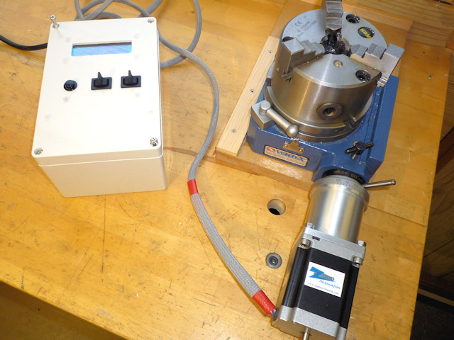
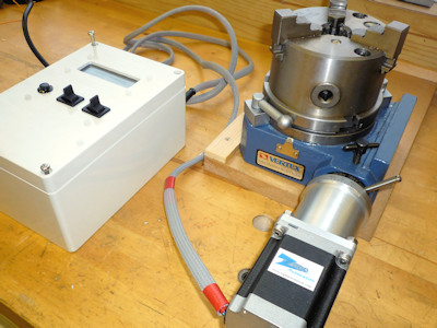
I recently read an article in Model Engineers Workshop Magazine (December 2016 issue 249) for adding a stepper motor drive to a rotary table. I don′t use my small Vertex rotary table very often but I thought this might be a useful project to learn a little about stepper motors and digital control of machinery. The article by Carl Wilson describes how to use an Arduino micro-controller to control the rotary division process. Much of the coding is contained in another article in Digital Machinist by Gary Liming. So no original thinking by me here, just a rehash of other engineers good work. All the links and useful information can be found in the Glossary at the end.
Prepping the table can be as simple as doing nothing, a complete strip down and re-build with thrust washers and the like or somewhere in between. There are a few articles on the web giving details (see glossary). Software setup and programming the Arduino is the quickest part and if you use Gary Liming′s software without alteration, the programming takes just a few seconds. Assembling the electronics is mainly about fitting the bits into the box and requires a bit of inginuity to fix things in place. The boards are fairly flimsy and things, like the display, tend not to be square or flat, I found.
The stepper motor mounting I made from three parts and assembled with Loctite and screws. I have no doubt there are other ways of making this or a suitable motor mount could be found ready made and adapted to fit the table. You will probably want to test things as you you go along rather than leave everything to the end. I discovered I had a faulty motor driver, easier to deal with whilst still uncased. I don′t think it makes makes any difference which order things are done.
This is covered elsewhere on the web in some detail so I have just made a few notes that may be of interest. Dismantling the table is quite straightforward, just look for allen headed grub screws at the bottom of deep holes. The notes refer to my 4" Vertex table.
Start off by removing the handle, the table locking clamps and the worm engagement lock. The handle is just one screw but watch out for the shaft key which is small and easily lost. Photo (2) shows the board I made to store the table with a cutout for the handle. The stepper motor will also need a similar storage solution. I used pliers and some cardboard to protect the finish to unscrew the table clamp handles. Remove the engagement lever and collar, two grub screws and it slides off, this is the part that the motor connector will attach to, it has three ready tapped holes for when used with division plates.
Remove the cam shaft securing and adjusting collar (4), four cap screws. Remove the grub screw that sets the worm engagement depth, found at the bottom of a deep hole (5). The worm shaft and cam bearing can now be removed as one unit, rotate the table and it will push the spindle out.
Turn the table upside down and remove the table bearing and adjustment plate (6), four cap screws. The table can now be removed, mine was pretty clean (7) not having been used much, there wasn′t even that much grease. Now that everything is apart it can all be cleaned re-greased and re-assembled. The worm drive shaft can be slid out of the cam adjuster by removing the collar, it is a ground shaft with an oilway and a very good fit in the cam adjuster.
Other than adjustment to remove backlash I didn′t make any changes to my rotary table, it was in fact pretty good before I started. If you have an older well used table it may take a bit more cleaning to remove old grease and any swarf that may have found it′s way inside.
Other parts worth note are the cam shaft retainer / bearing (4) and the table retainer / bearing (6). These both feature four cap screws which bolt the item in place and four grub screws which act as jack-screws to prevent clamping the rotating part. When reassembling it is worth adjusting these carefully to limit the table lifting whilst still turning freely and likewise to prevent the cam shaft moving in and out. I noticed with the table bearing / retainer that there was a noticeable stiff spot so it is worth rotating the table through a full 360° whilst adjusting. The cam shaft could be locked in place if you think there is no need to disengage the worm gear. Last bit is to set the worm engagement, this is controlled by a grub screw at the side (5) which engages with a slot in the cam shaft to prevent rotation. If you undo the grub screw and fully engage the worm it will be very difficult to turn, tighten the grub screw just enough so that the worm turns easily with a minimum of backlash.
Not much to this really but first you will need to go to the Arduino website and download the Integrated Development Environment (IDE) software. This is basically a fairly lightweight program that runs on your PC (Windows, Mac or Linux) and allows you to edit programs (sketches in Arduino speak) and upload to the Arduino board. You will also need to download Gary Liming′s software. Once the software is downloaded installation is straightforward. The Arduino IDE is self-installing from an exe file in Windows. Gary Liming′s programs come as a zip file which needs un-zipping to a folder. Once unzipped, double click on the "Stepindex23.ino" file and it will start the Arduino IDE and load the program.
All being well you should now have a screen like something like those above. Click on the image to read the text. Affix the LCD shield to the Uno making sure that all the pins are in the right places and none of the connectors is bent. Plug the Uno into the PC using a USB cable, often supplied with the board. The Uno will be powered by the USB connection. First thing to do is go to the "Tools" menu (10) and set the type of board. All being well the software should then report that it is talking to the Uno, bottom right of the IDE, something like "Arduino/Genuino UNO on COM4". You should also be able to click on the "Port" section of the menu to assign a COM port. If this isn′t working and the Port section is greyed out it may be driver related.
Arduino micro-controllers are mainly programmed using the C++ programming language or at least a subset of C++, so the programs are fairly understandable for basic editing. The first few lines of the program (11) are used to set parameters used later. These can be adjusted now, the program is well commented, or left until later when everything is assembled. You may wish to alter gear ratios or even remove some items. There is more help in the readme files that come in the program zip-file. If you are a C++ programmer the world is your oyster, the menu items can be moved around or even removed if you don′t need a particular function. You may wish to experiment with some of the delay timings to help de-bounce the keys but this is probably better done during final testing.
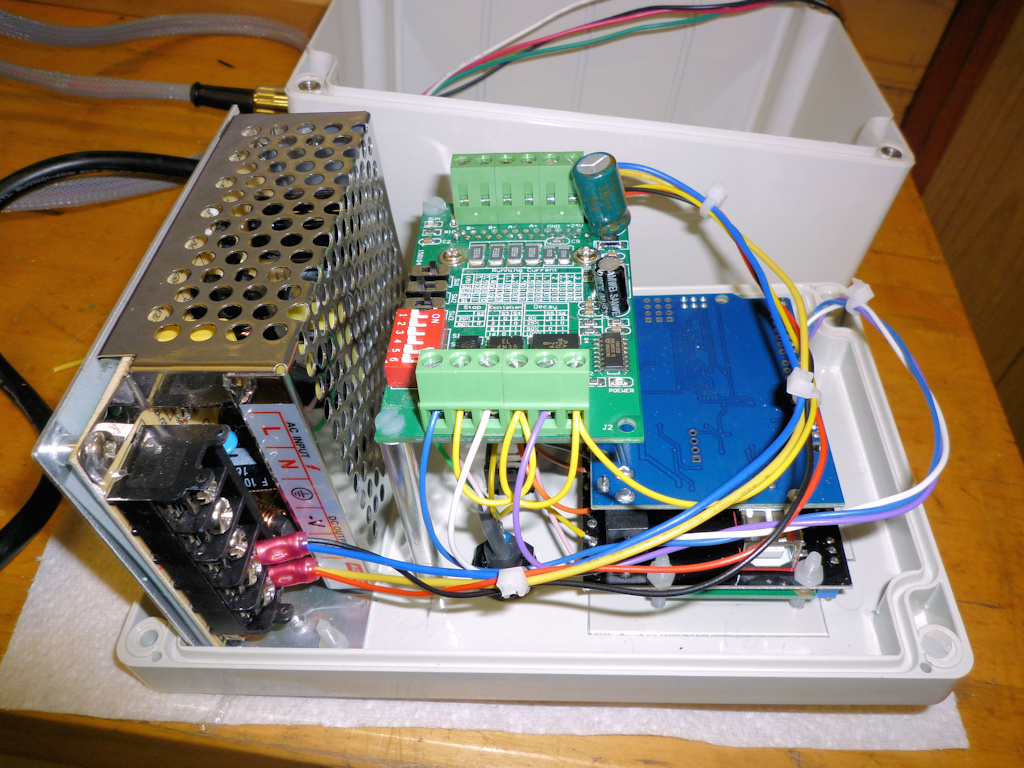
The parts are shown (12) above and are the Arduino Uno, the LCD shield, the cable gland, TB6560 stepper driver, switches, plug, socket and power supply. The circuit boards are all pretty flimsy and the mounting holes are very close to the edges. The LCD shield has a seperate smaller board for the LCD soldered on top and the two boards were not particularly parallel. There is also a multi-turn variable resistor on the board which cunningly sticks up higher than the LCD face. If you are adept with a soldering iron it can be re-positioned on the other side of the PCB. I solved the non-flush pot problem by using a 1.5mm clear polycarbonate sheet between the box lid and LCD with a small cutout for the variable resistor.
I fitted as much as I could to the box lid, only the mains in and stepper out are fitted to the box. The display needs a cutout in the lid as do the three switches and a number of 3mm holes for various mounting screws. Once I had worked out the position of all the bits I marked the inside of the box lid for the position of the LCD and switch cutouts. I set this up on the mill and used a 5mm slot drill to remove the cutouts, the ABS machines very easily. I fixed the lid to an off-cut of MDF with woodscrews through the mounting holes, I also used double sided tape to make sure nothing moved. A couple of T-nuts and studs fixed the MDF to the mill table (13). With hindsight the double sided tape was overkill, it took me longer to get it off the lid than it did to do the machining. The corners of the switch cutouts I filed square, I drilled the various mounting bolt holes by hand as I did for the other round holes opening them up as necessary with a taper reamer and file.
I made the two flat plates and then fitted the motor, flexible coupling and rotary table together to measure the shortest length of tube that would work. The dimensions for the motor mounting plate were copied from the motor spec sheet.
I used another bit of 3" x ¼" bar to turn the plate that bolts to the rotary table. I drilled a 10mm hole in the centre of the plate and used a length of studding to hold it (22). The studding has two nuts locked to it which fit against the back of the chuck jaws and a nut and washer clamp the plate against the front of the jaws, there is a centre in the outboard end of the studding for support. I used a trepanning tool to remove the corners and then turned the O.D. to to size.
When the R.T. mounting plate is the correct diameter add a step 3mm deep with 38.1mm diameter to create a short spigot to fit the tube bore. Remove from the mandrel (studding) and mount holding the just turned spigot (23), bore out the centre hole to 21mm to fit the R.T. collar. To finish this part it need the three mounting holes drilled to match the table. I clamped the table index ring to the plate, they should be the same diameter, then spotted through with a drill that just cleared the threads in the index ring. Unclamp and drill the holes 5mm, there is no other alignment so keep the holes small, don"t use an M5 clearance drill.
The three parts are "glued" together, I used Loctite 603 which is a high strength oil tolerant retainer. Check alignment before joining, it will depend on the orientation of the holes in the index collar on the R.T. probably easier to join the tube to the table end first and then bolt it in place. The motor mount can then be aligned so that it is square when in use. I had an interesting experience when I first tried assembly. applied the Loctite placed suitable weight on top and left overnight. The following day removed the weight picked it up and it came apart. Apparently Loctite "goes off" still mine was a few years old! If you want to add screws it is probably easier to do this after assembly, I used 3 M3 C/S screws in each end, a bit belt and braces as either screws or adhesive alone will probably do the job.
Not much to this really, first bolt the connector to the rotary table. Slide in the flexible coupling and tighten onto the table drive, I aligned it so that the grub screw would tighten into the keyway. Fit the motor using four M5 capscews, nuts and shakeproof washers. Tighten the coupling onto the motor shaft and thats the mechanical bit done.
To test I went through each menu item in turn and made sure it did what it was supposed to. I discovered that clockwise and anti-clockwise were reversed but this can be adjusted in the software. I also discovered that I had wired one switch back to front and needed to reverse the leads fortunately just swapping a couple of push on connectors. Found that the motor vibrated rather heavily, haven′t got to the cause of that yet. I also set the table to zero on it′s scale and checked that the angle turned matched what the display said for a full 360° - it did.
With a bit of work on the software, to slow the motor down, I don′t see why the table could not be operated under power, to mill say a semi-circular slot. WIll also need a bit of work on the switch de-bounce software for this to ensure reliability, as it is it is easy to double press keys. Nice little project a good introduction to both the Arduino and to stepper motors neither of which I had used before.
As I had to take everything apart I added a reset button (29) by soldering leads to the back of the shield button in the same way as for the other buttons. Caused me some aggravation as the first button I found in my "bits that will be useful one day box" remained steadfastly open-circuit when pressed, still it was probably 30 years old! Last but not least a short video (30) which shows the table spinning quietly in run mode and then vibrating in step and angle mode. It makes me think this might be software generated as that is the only difference between the modes.
Model Engineers Workshop Forum- thread discussing the original magazine article and various points arising including some useful information about variations in the Arduino hardware, particularly the LCD shield.
Gary Liming′s Website- describes the making of the original step-indexer which could be used in place of a rotary table and outlines the software in a bit more detail.
Arduino Home Page- has all the information about the Arduino project. You can download the IDE (Integrated Development Environment) from here which you will need to program the micro-controller board.
CH340G driver- Some boards use the CH340G USB/serial chip as a cheaper alternative to the FTDI chip, this is the driver download link. The FTDI standard driver is installed when you setup the Arduino IDE.
Model Engine Maker Forum- thread covering the preparation of a Vertex rotary table ready for automation. This was done by John "Bogstandard" Moore in readiness for the Division Master system but the mechanics are the same.
The list above is for the major parts required for the project. The suppliers are those I used and the prices were correct in January 2017. (Please note the links to some of these items seem to change weekly, apologies if they don′t work) I make no particular recommendation as to the suppliers it is just where I found the bits needed, it is likely that better/cheaper/different parts are available from myriad locations on the web. In addition to the bits listed you will need - hook-up wire, solder, nuts, bolts, spacers, cable ties, crimp connectors and sleeving. Please note that the above table doesn"t display well on a small screen, try rotating to landscape to view!
Many of the links in the Glossary and particularly the Parts List table have gone missing over time so I have tried to update them with currently available parts and information. In fact none of the parts are particularly critical and a bit of web searching will find suitable replacements. The Model Engineer Forum link is still active and one of the later additions is the replacement of the switches with a cheaply available numeric keypad. I haven"t carried out this mod but it looks quite interesting.

Along 3 years I have been trying several leg mechanism, at first I decided to do a simple desing with tibial motor where placed on femur joint.This design had several problems, like it wasn"t very robust and the most importat is that having the motor (with big mass) that far from the rotating axis, caused that in some movements it generate unwanted dynamics to the robot body, making controlability worse.New version have both motors of femur/tibial limb at coxa frame, this ends with a very simple setup and at the same time, the heaviest masses of the mechanism are centered to the rotating axis of coxa limb, so even though the leg do fast movements, inertias won"t be strong enough to affect the hole robot mass, achieving more agility.Inverse Kinematics of the mechanismAfter building it I notice that this mechanism was very special for another reason, at the domain the leg normally moves, it acts as a diferential mecanism, this means that torque is almost all the time shared between both motor of the longer limbs. That was an improvent since with the old mechanism tibial motor had to hold most of the weight and it was more forced than the one for femur.To visualize this, for the same movement, we can see how tibial motor must travel more arc of angel that the one on the new version.In order to solve this mechanism, just some trigonometry is needed. Combining both cosine and sine laws, we can obtain desired angle (the one between femur and tibia) with respect to the angle the motor must achieve.Observing these equations, with can notice that this angle (the one between femur and tibia) depends on both servos angles, which means both motors are contributing to the movement of the tibia.Calibration of servosAnother useful thing to do if we want to control servo precisely is to print a calibration tool for our set up. As shown in the image below, in order to know where real angles are located, angle protactor is placer just in the origin of the rotating joint, and choosing 2 know angles we can match PWM signal to the real angles we want to manipulate simply doing a lineal relation between angles and PWM pulse length.Then a simple program in the serial console can be wrtten to let the user move the motor to the desired angle. This way the calibration process is only about placing motor at certain position and everything is done and we won"t need to manually introduce random values that can be a very tedious task.With this I have achieved very good calibrations on motors, which cause the robot to be very simetrial making the hole system more predictable. Also the calibration procedure now is very easy to do, as all calculations are done automatically. Check Section 1 for the example code for calibration.More about this can be seen in the video below, where all the building process is shown as well as the new leg in action.SECTION 1:In the example code below, you can see how calibration protocol works, it is just a function called calibrationSecuence() which do all the work until calibration is finished. So you only need to call it one time to enter calibration loop, for example by sending a "c" character thought the serial console.Also some useful function are used, like moving motor directly with analogWrite functions which all the calculations involved, this is a good point since no interrupts are used.This code also have the feature to calibrate the potentiometer coming from each motor.#define MAX_PULSE 2500 #define MIN_PULSE 560 /*---------------SERVO PIN DEFINITION------------------------*/ int m1 = 6;//FR int m2 = 5; int m3 = 4; int m4 = 28;//FL int m5 = 29; int m6 = 36; int m7 = 3;//BR int m8 = 2; int m9 = 1; int m10 = 7;//BL int m11 = 24; int m12 = 25; int m13 = 0;//BODY /*----------------- CALIBRATION PARAMETERS OF EACH SERVO -----------------*/ double lowLim[13] = {50, 30, 30, 50, 30, 30, 50, 30, 30, 50, 30, 30, 70}; double highLim[13] = {130, 150, 150, 130, 150, 150, 130, 150, 150, 130, 150, 150, 110}; double a[13] = { -1.08333, -1.06667, -1.07778, //FR -1.03333, 0.97778, 1.01111, //FL 1.03333, 1.05556, 1.07778, //BR 1.07500, -1.07778, -1.00000, //BL 1.06250 }; double b[13] = {179.0, 192.0, 194.5, //FR 193.0, 5.5, -7.5, //FL 7.0, -17.0, -16.0, //BR -13.5, 191.5, 157.0, //BL -0.875 }; double ae[13] = {0.20292, 0.20317, 0.19904 , 0.21256, -0.22492, -0.21321, -0.21047, -0.20355, -0.20095, -0.20265, 0.19904, 0.20337, -0.20226 }; double be[13] = { -18.59717, -5.70512, -2.51697, -5.75856, 197.29411, 202.72169, 185.96931, 204.11902, 199.38663, 197.89534, -5.33768, -32.23424, 187.48058 }; /*--------Corresponding angles you want to meassure at in your system-----------*/ double x1[13] = {120, 135, 90, 60, 135 , 90, 120, 135, 90, 60, 135, 90, 110}; //this will be the first angle you will meassure double x2[13] = {60, 90, 135, 120, 90, 135, 60, 90, 135, 120, 90, 135, 70};//this will be the second angle you will meassure for calibration /*--------You can define a motor tag for each servo--------*/ String motorTag[13] = {"FR coxa", "FR femur", "FR tibia", "FL coxa", "FL femur", "FL tibia", "BR coxa", "BR femur", "BR tibia", "BL coxa", "BL femur", "BL tibia", "Body angle" }; double ang1[13] = {0, 0, 0, 0, 0, 0, 0, 0, 0, 0, 0, 0, 0}; double ang2[13] = {0, 0, 0, 0, 0, 0, 0, 0, 0, 0, 0, 0, 0}; float xi[500]; float yi[500]; float fineAngle; float fineL; float fineH; int motorPin; int motor = 0; float calibrationAngle; float res = 1.0; float ares = 0.5; float bres = 1.0; float cres = 4.0; float rawAngle; float orawAngle; char cm; char answer; bool interp = false; bool question = true; bool swing = false; int i; double eang; int freq = 100; // PWM frecuency can be choosen here. void connectServos() { analogWriteFrequency(m1, freq); //FR coxa digitalWrite(m1, LOW); pinMode(m1, OUTPUT); analogWriteFrequency(m2, freq); //femur digitalWrite(m2, LOW); pinMode(m2, OUTPUT); analogWriteFrequency(m3, freq); //tibia digitalWrite(m3, LOW); pinMode(m3, OUTPUT); analogWriteFrequency(m4, freq); //FL coxa digitalWrite(m4, LOW); pinMode(m4, OUTPUT); analogWriteFrequency(m5, freq); //femur digitalWrite(m5, LOW); pinMode(m5, OUTPUT); analogWriteFrequency(m6, freq); //tibia digitalWrite(m6, LOW); pinMode(m6, OUTPUT); analogWriteFrequency(m7, freq); //FR coxa digitalWrite(m7, LOW); pinMode(m7, OUTPUT); analogWriteFrequency(m8, freq); //femur digitalWrite(m8, LOW); pinMode(m8, OUTPUT); analogWriteFrequency(m9, freq); //tibia digitalWrite(m9, LOW); pinMode(m9, OUTPUT); analogWriteFrequency(m10, freq); //FR coxa digitalWrite(m10, LOW); pinMode(m10, OUTPUT); analogWriteFrequency(m11, freq); //femur digitalWrite(m11, LOW); pinMode(m11, OUTPUT); analogWriteFrequency(m12, freq); //tibia digitalWrite(m12, LOW); pinMode(m12, OUTPUT); analogWriteFrequency(m13, freq); //body digitalWrite(m13, LOW); pinMode(m13, OUTPUT); } void servoWrite(int pin , double angle) { float T = 1000000.0f / freq; float usec = float(MAX_PULSE - MIN_PULSE) * (angle / 180.0) + (float)MIN_PULSE; uint32_t duty = int(usec / T * 4096.0f); analogWrite(pin , duty); } double checkLimits(double angle , double lowLim , double highLim) { if ( angle >= highLim ) { angle = highLim; } if ( angle <= lowLim ) { angle = lowLim; } return angle; } int motorInfo(int i) { enc1 , enc2 , enc3 , enc4 , enc5 , enc6 , enc7 , enc8 , enc9 , enc10 , enc11 , enc12 , enc13 = readEncoders(); if (i == 0) { rawAngle = enc1; motorPin = m1; } else if (i == 1) { rawAngle = enc2; motorPin = m2; } else if (i == 2) { rawAngle = enc3; motorPin = m3; } else if (i == 3) { rawAngle = enc4; motorPin = m4; } else if (i == 4) { rawAngle = enc5; motorPin = m5; } else if (i == 5) { rawAngle = enc6; motorPin = m6; } else if (i == 6) { rawAngle = enc7; motorPin = m7; } else if (i == 7) { rawAngle = enc8; motorPin = m8; } else if (i == 8) { rawAngle = enc9; motorPin = m9; } else if (i == 9) { rawAngle = enc10; motorPin = m10; } else if (i == 10) { rawAngle = enc11; motorPin = m11; } else if (i == 11) { rawAngle = enc12; motorPin = m12; } else if (i == 12) { rawAngle = enc13; motorPin = m13; } return rawAngle , motorPin; } void moveServos(double angleBody , struct vector anglesServoFR , struct vector anglesServoFL , struct vector anglesServoBR , struct vector anglesServoBL) { //FR anglesServoFR.tetta = checkLimits(anglesServoFR.tetta , lowLim[0] , highLim[0]); fineAngle = a[0] * anglesServoFR.tetta + b[0]; servoWrite(m1 , fineAngle); anglesServoFR.alpha = checkLimits(anglesServoFR.alpha , lowLim[1] , highLim[1]); fineAngle = a[1] * anglesServoFR.alpha + b[1]; servoWrite(m2 , fineAngle); anglesServoFR.gamma = checkLimits(anglesServoFR.gamma , lowLim[2] , highLim[2]); fineAngle = a[2] * anglesServoFR.gamma + b[2]; servoWrite(m3 , fineAngle); //FL anglesServoFL.tetta = checkLimits(anglesServoFL.tetta , lowLim[3] , highLim[3]); fineAngle = a[3] * anglesServoFL.tetta + b[3]; servoWrite(m4 , fineAngle); anglesServoFL.alpha = checkLimits(anglesServoFL.alpha , lowLim[4] , highLim[4]); fineAngle = a[4] * anglesServoFL.alpha + b[4]; servoWrite(m5 , fineAngle); anglesServoFL.gamma = checkLimits(anglesServoFL.gamma , lowLim[5] , highLim[5]); fineAngle = a[5] * anglesServoFL.gamma + b[5]; servoWrite(m6 , fineAngle); //BR anglesServoBR.tetta = checkLimits(anglesServoBR.tetta , lowLim[6] , highLim[6]); fineAngle = a[6] * anglesServoBR.tetta + b[6]; servoWrite(m7 , fineAngle); anglesServoBR.alpha = checkLimits(anglesServoBR.alpha , lowLim[7] , highLim[7]); fineAngle = a[7] * anglesServoBR.alpha + b[7]; servoWrite(m8 , fineAngle); anglesServoBR.gamma = checkLimits(anglesServoBR.gamma , lowLim[8] , highLim[8]); fineAngle = a[8] * anglesServoBR.gamma + b[8]; servoWrite(m9 , fineAngle); //BL anglesServoBL.tetta = checkLimits(anglesServoBL.tetta , lowLim[9] , highLim[9]); fineAngle = a[9] * anglesServoBL.tetta + b[9]; servoWrite(m10 , fineAngle); anglesServoBL.alpha = checkLimits(anglesServoBL.alpha , lowLim[10] , highLim[10]); fineAngle = a[10] * anglesServoBL.alpha + b[10]; servoWrite(m11 , fineAngle); anglesServoBL.gamma = checkLimits(anglesServoBL.gamma , lowLim[11] , highLim[11]); fineAngle = a[11] * anglesServoBL.gamma + b[11]; servoWrite(m12 , fineAngle); //BODY angleBody = checkLimits(angleBody , lowLim[12] , highLim[12]); fineAngle = a[12] * angleBody + b[12]; servoWrite(m13 , fineAngle); } double readEncoderAngles() { enc1 , enc2 , enc3 , enc4 , enc5 , enc6 , enc7 , enc8 , enc9 , enc10 , enc11 , enc12 , enc13 = readEncoders(); eang1 = ae[0] * enc1 + be[0]; eang2 = ae[1] * enc2 + be[1]; eang3 = ae[2] * enc3 + be[2]; eang4 = ae[3] * enc4 + be[3]; eang5 = ae[4] * enc5 + be[4]; eang6 = ae[5] * enc6 + be[5]; eang7 = ae[6] * enc7 + be[6]; eang8 = ae[7] * enc8 + be[7]; eang9 = ae[8] * enc9 + be[8]; eang10 = ae[9] * enc10 + be[9]; eang11 = ae[10] * enc11 + be[10]; eang12 = ae[11] * enc12 + be[11]; eang13 = ae[12] * enc13 + be[12]; return eang1 , eang2 , eang3 , eang4 , eang5 , eang6 , eang7 , eang8 , eang9 , eang10 , eang11 , eang12 , eang13; } void calibrationSecuence( ) { //set servos at their middle position at firstt for (int i = 0; i <= 12; i++) { rawAngle , motorPin = motorInfo(i); servoWrite(motorPin , 90); } // sensorOffset0 = calibrateContacts(); Serial.println(" "); Serial.println("_________________________________SERVO CALIBRATION ROUTINE_________________________________"); Serial.println("___________________________________________________________________________________________"); Serial.println("(*) Don"t send several caracter at the same time."); delay(500); Serial.println(" "); Serial.println("Keyboard: "x"-> EXIT CALIBRATION. "c"-> ENTER CALIBRATION."); Serial.println(" "i"-> PRINT INFORMATION. "); Serial.println(" "); Serial.println(" "n"-> CHANGE MOTOR (+). "b" -> CHANGE MOTOR (-)."); Serial.println(" "m"-> START CALIBRATION."); Serial.println(" "q"-> STOP CALIBRATION."); Serial.println(" "); Serial.println(" "r"-> CHANGE RESOLUTION."); Serial.println(" "p"-> ADD ANGLE. "o"-> SUBTRACT ANGLE. "); Serial.println(" "s"-> SAVE ANGLE."); delay(500); Serial.println(" "); Serial.println("---------------------------------------------------------------------------------------------------"); Serial.print("SELECTED MOTOR: "); Serial.print(motorTag[motor]); Serial.print(". SELECTED RESOLUTION: "); Serial.println(res); while (CAL == true) { if (Serial.available() > 0) { cm = Serial.read(); if (cm == "x") { Serial.println("Closing CALIBRATION program..."); CAL = false; secuence = false; startDisplay(PAGE); angleBody = 90; anglesIKFR.tetta = 0.0; anglesIKFR.alpha = -45.0; anglesIKFR.gamma = 90.0; anglesIKFL.tetta = 0.0; anglesIKFL.alpha = -45.0; anglesIKFL.gamma = 90.0; anglesIKBR.tetta = 0.0; anglesIKBR.alpha = 45.0; anglesIKBR.gamma = -90.0; anglesIKBL.tetta = 0.0; anglesIKBL.alpha = 45.0; anglesIKBL.gamma = -90.0; } else if (cm == "i") { // + Serial.println(" "); Serial.println("---------------------------------------------------------------------------------------------------"); Serial.println("---------------------------------------------------------------------------------------------------"); Serial.println("(*) Don"t send several caracter at the same time."); delay(500); Serial.println(" "); Serial.println("Keyboard: "x"-> EXIT CALIBRATION. "c"-> ENTER CALIBRATION."); Serial.println(" "i"-> PRINT INFORMATION. "); Serial.println(" "); Serial.println(" "n"-> CHANGE MOTOR (+). "b" -> CHANGE MOTOR (-)."); Serial.println(" "m"-> START CALIBRATION."); Serial.println(" "q"-> STOP CALIBRATION."); Serial.println(" "); Serial.println(" "r"-> CHANGE RESOLUTION."); Serial.println(" "p"-> ADD ANGLE. "o"-> SUBTRACT ANGLE. "s"-> SAVE ANGLE."); Serial.println(" "); delay(500); Serial.println(" "); Serial.println("---------------------------------------------------------------------------------------------------"); Serial.println(" "); Serial.print("SELECTED MOTOR: "); Serial.print(motorTag[motor]); Serial.print(". SELECTED RESOLUTION: "); Serial.println(res); Serial.println("Actual parameters of the motor: "); Serial.print("High limit: "); Serial.print(highLim[motor]); Serial.print(" Low limit: "); Serial.print(lowLim[motor]); Serial.print(" Angle 1: "); Serial.print(ang1[motor]); Serial.print(" Angle 2: "); Serial.println(ang2[motor]); Serial.println("---------------------------------------------------------------------------------------------------"); } else if (cm == "m") { // + secuence = true; } else if (cm == "s") { // + } else if (cm == "n") { // + motor++; if (motor >= 13) { motor = 0; } Serial.print("SELECTED MOTOR: "); Serial.println(motorTag[motor]); } else if (cm == "b") { // + motor--; if (motor < 0) { motor = 13 - 1; } Serial.print("SELECTED MOTOR: "); Serial.println(motorTag[motor]); } else if (cm == "r") { // + if (res == ares) { res = bres; } else if (res == bres) { res = cres; } else if (res == cres) { res = ares; } Serial.print("SELECTED RESOLUTION: "); Serial.println(res); } } if (secuence == true) { Serial.print("Starting secuence for motor: "); Serial.println(motorTag[motor]); for (int i = 0; i <= 30; i++) { delay(20); Serial.print("."); } Serial.println("."); while (question == true) { unsigned long currentMicros = micros(); if (currentMicros - previousMicros >= 100000) { previousMicros = currentMicros; if (Serial.available() > 0) { answer = Serial.read(); if (answer == "y") { question = false; interp = true; secuence = true; } else if (answer == "n") { question = false; interp = false; secuence = true; } else { Serial.println("Please, select Yes(y) or No(n)."); } } } } answer = "t"; question = true; if (interp == false) { Serial.println("___"); Serial.println(" | Place motor at 1ts position and save angle"); Serial.println(" | This position can be the higher one"); rawAngle , motorPin = motorInfo(motor); calibrationAngle = 90; //start calibration at aproximate middle position of the servo. while (secuence == true) { /* find first calibration angle */ if (Serial.available() > 0) { cm = Serial.read(); if (cm == "p") { // + Serial.print(" | +"); Serial.print(res); Serial.print(" : "); calibrationAngle = calibrationAngle + res; servoWrite(motorPin , calibrationAngle); Serial.println(calibrationAngle); } else if (cm == "o") { // - Serial.print(" | -"); Serial.print(res); Serial.print(" : "); calibrationAngle = calibrationAngle - res; servoWrite(motorPin , calibrationAngle); Serial.println(calibrationAngle); } else if (cm == "r") { // + if (res == ares) { res = bres; } else if (res == bres) { res = cres; } else if (res == cres) { res = ares; } Serial.print("SELECTED RESOLUTION: "); Serial.println(res); } else if (cm == "q") { // quit secuence secuence = false; Serial.println(" | Calibration interrupted!!"); } else if (cm == "s") { // save angle ang1[motor] = calibrationAngle; secuence = false; Serial.print(" | Angle saved at "); Serial.println(calibrationAngle); } } } if (cm == "q") { Serial.println(" |"); } else { secuence = true; Serial.println("___"); Serial.println(" | Place motor at 2nd position and save angle"); Serial.println(" | This position can be the lower one"); } while (secuence == true) { /* find second calibration angle */ if (Serial.available() > 0) { cm = Serial.read(); if (cm == "p") { // + Serial.print(" | +"); Serial.print(res); Serial.print(" : "); calibrationAngle = calibrationAngle + res; servoWrite(motorPin , calibrationAngle); Serial.println(calibrationAngle); } else if (cm == "o") { // - Serial.print(" | -"); Serial.print(res); Serial.print(" : "); calibrationAngle = calibrationAngle - res; servoWrite(motorPin , calibrationAngle); Serial.println(calibrationAngle); } else if (cm == "r") { // + if (res == ares) { res = bres; } else if (res == bres) { res = cres; } else if (res == cres) { res = ares; } Serial.print("SELECTED RESOLUTION: "); Serial.println(res); } else if (cm == "q") { // quit secuence secuence = false; Serial.println(" | Calibration interrupted!!"); } else if (cm == "s") { // save angle ang2[motor] = calibrationAngle; secuence = false; Serial.print(" | Angle saved at "); Serial.println(calibrationAngle); } } } /*--------------------start calibration calculations------------------*/ if (cm == "q") { Serial.println("___|"); Serial.println("Calibration finished unespected."); Serial.println(" Select another motor."); Serial.print("SELECTED MOTOR: "); Serial.print(motorTag[motor]); Serial.print(". SELECTED RESOLUTION: "); Serial.println(res); } else { Serial.println("___"); Serial.println(" |___"); Serial.print( " | | Interpolating for motor: "); Serial.println(motorTag[motor]); secuence = true; //real angle is calculated interpolating both angles to a linear relation. a[motor] = (ang2[motor] - ang1[motor]) / (x2[motor] - x1[motor]); b[motor] = ang1[motor] - x1[motor] * (ang2[motor] - ang1[motor]) / (x2[motor] - x1[motor]); Serial.println(" | |"); } interp = true; } /*---------------------------make swing movement to interpolate motor encoder-----*/ if (interp == true and secuence == true) { delay(200); double x; int k = 0; int stp = 180; swing = true; i = 0; orawAngle , motorPin = motorInfo(motor); previousMicros = 0; while (swing == true) { // FIRST unsigned long currentMicros = micros(); if (currentMicros - previousMicros >= 10000) { // save the last time you blinked the LED previousMicros = currentMicros; x = x2[motor]; calibrationAngle = a[motor] * x + b[motor]; servoWrite(motorPin , calibrationAngle); rawAngle , motorPin = motorInfo(motor); if ((i % 3) == 0) { yi[k+1] = x; xi[k] = rawAngle; Serial.print(" | | Real ang: "); Serial.print(x); Serial.print(" -> Servo ang: "); Serial.print(calibrationAngle); Serial.print(" Enc: "); Serial.println(rawAngle); k++; } if (i >= stp) { swing = false; } i++; } } swing = true; i = 0; while (swing == true) { // moving unsigned long currentMicros = micros(); if (currentMicros - previousMicros >= 10000) { // save the last time you blinked the LED previousMicros = currentMicros; x = x2[motor] + float(i) * (x1[motor] - x2[motor]) / stp; calibrationAngle = a[motor] * x + b[motor]; servoWrite(motorPin , calibrationAngle); rawAngle , motorPin = motorInfo(motor); if ((i % 6) == 0) { yi[k+1] = x; xi[k] = rawAngle; Serial.print(" | | Real ang: "); Serial.print(x); Serial.print(" -> Servo ang: "); Serial.print(calibrationAngle); Serial.print(" Enc: "); Serial.println(rawAngle); k++; } if (i >= stp) { swing = false; } i++; } } swing = true; i = 0; while (swing == true) { // SECOND unsigned long currentMicros = micros(); if (currentMicros - previousMicros >= 10000) { // save the last time you blinked the LED previousMicros = currentMicros; x = x1[motor]; calibrationAngle = a[motor] * x + b[motor]; servoWrite(motorPin , calibrationAngle); rawAngle , motorPin = motorInfo(motor); if ((i % 3) == 0) { yi[k+1] = x; xi[k] = rawAngle; Serial.print(" | | Real ang: "); Serial.print(x); Serial.print(" -> Servo ang: "); Serial.print(calibrationAngle); Serial.print(" Enc: "); Serial.println(rawAngle); k++; } if (i >= stp) { swing = false; } i++; } } swing = true; i = 0; while (swing == true) { // moving unsigned long currentMicros = micros(); if (currentMicros - previousMicros >= 10000) { // save the last time you blinked the LED previousMicros = currentMicros; x = x1[motor] + float(i) * (x2[motor] - x1[motor]) / stp; calibrationAngle = a[motor] * x + b[motor]; servoWrite(motorPin , calibrationAngle); rawAngle , motorPin = motorInfo(motor); if ((i % 6) == 0) { yi[k+1] = x; xi[k] = rawAngle; Serial.print(" | | Real ang: "); Serial.print(x); Serial.print(" -> Servo ang: "); Serial.print(calibrationAngle); Serial.print(" Enc: "); Serial.println(rawAngle); k++; } if (i >= stp) { swing = false; } i++; } } swing = true; i = 0; while (swing == true) { // FIRST unsigned long currentMicros = micros(); if (currentMicros - previousMicros >= 10000) { // save the last time you blinked the LED previousMicros = currentMicros; x = x2[motor]; calibrationAngle = a[motor] * x + b[motor]; servoWrite(motorPin , calibrationAngle); rawAngle , motorPin = motorInfo(motor); if ((i % 3) == 0) { yi[k+1] = x; xi[k] = rawAngle; Serial.print(" | | Real ang: "); Serial.print(x); Serial.print(" -> Servo ang: "); Serial.print(calibrationAngle); Serial.print(" Enc: "); Serial.println(rawAngle); k++; } if (i >= stp) { swing = false; } i++; } } swing = true; i = 0; while (swing == true) { // moving unsigned long currentMicros = micros(); if (currentMicros - previousMicros >= 10000) { // save the last time you blinked the LED previousMicros = currentMicros; x = x2[motor] + float(i) * (x1[motor] - x2[motor]) / stp; calibrationAngle = a[motor] * x + b[motor]; servoWrite(motorPin , calibrationAngle); rawAngle , motorPin = motorInfo(motor); if ((i % 6) == 0) { yi[k+1] = x; xi[k] = rawAngle; Serial.print(" | | Real ang: "); Serial.print(x); Serial.print(" -> Servo ang: "); Serial.print(calibrationAngle); Serial.print(" Enc: "); Serial.println(rawAngle); k++; } if (i >= stp) { swing = false; } i++; } } swing = true; i = 0; while (swing == true) { // SECOND unsigned long currentMicros = micros(); if (currentMicros - previousMicros >= 10000) { // save the last time you blinked the LED previousMicros = currentMicros; x = x1[motor]; calibrationAngle = a[motor] * x + b[motor]; servoWrite(motorPin , calibrationAngle); rawAngle , motorPin = motorInfo(motor); if ((i % 3) == 0) { yi[k+1] = x; xi[k] = rawAngle; Serial.print(" | | Real ang: "); Serial.print(x); Serial.print(" -> Servo ang: "); Serial.print(calibrationAngle); Serial.print(" Enc: "); Serial.println(rawAngle); k++; } if (i >= stp) { swing = false; } i++; } } Serial.println(" | | Interpolation finished!"); /*-------Calculate linear interpolation of the encoder from 60 meassures done in swing------*/ double sx = 0; double sy = 0; double sx2 = 0; double sy2 = 0; double sxy = 0; double xmean = 0; double ymean = 0; int n = 300; for (int i = 0 ; i < n ; i++) { sx += xi[i+10]; sy += yi[i+10]; sx2 += xi[i+10] * xi[i+10]; sy2 += yi[i+10] * yi[i+10]; sxy += xi[i+10] * yi[i+10]; } ae[motor] = (n * sxy - sx * sy) / (n * sx2 - sx * sx); //sxy / sx2; // be[motor] = (sy - ae[motor] * sx) / n; //ymean - ae[motor] * xmean; Serial.println(" | | Moving back to ZERO position."); // turn the motor back to middle position swing = true; i = 0; while (swing == true) { unsigned long currentMicros = micros(); if (currentMicros - previousMicros >= 10000) { // save the last time you blinked the LED previousMicros = currentMicros; x = x1[motor] + float(i) * (90 - x1[motor]) / 60; calibrationAngle = a[motor] * x + b[motor]; servoWrite(motorPin , calibrationAngle); rawAngle , motorPin = motorInfo(motor); eang = ae[motor] * rawAngle + be[motor]; if ((i % 4) == 0) { Serial.print(" | | Servo ang: "); Serial.print(calibrationAngle); Serial.print(" -> Real ang: "); Serial.print(x); Serial.print(" -> Encoder ang: "); Serial.println(eang); } if (i >= 60) { swing = false; } i++; } } Serial.println("___|___|"); Serial.println(" | "); Serial.println("___"); Serial.println(" | Calibration finished satisfactory. Results data:"); Serial.print(" | HIGH lim: "); Serial.print(highLim[motor]); Serial.print(" LOW lim: "); Serial.println(lowLim[motor]); Serial.print(" | angle 1: "); Serial.print(ang1[motor]); Serial.print(" angle 2 "); Serial.println(ang2[motor]); Serial.print(" | Regression Motor a: "); Serial.print(a[motor], 5); Serial.print(" b: "); Serial.println(b[motor], 5); Serial.print(" | Regression Encoder a: "); Serial.print(ae[motor], 5); Serial.print(" b: "); Serial.println(be[motor], 5); Serial.println(" |"); Serial.println(" | ______________________________________________________________"); Serial.println(" | | |"); Serial.println(" | | This code won"t be able to save the updated parameters |"); Serial.println(" | | once the robot is shutted down. |"); Serial.println(" | | |"); Serial.println(" | | Please, write down the results |"); Serial.println(" | | and save them in the definition of each variable. |"); Serial.println(" | |_____________________________________________________________|"); Serial.println(" |"); Serial.println("___|"); Serial.println(" Select another motor."); Serial.print("SELECTED MOTOR: "); Serial.print(motorTag[motor]); Serial.print(". SELECTED RESOLUTION: "); Serial.println(res); } interp = false; secuence = false; } } SAFE = false; Serial.println("Calibration killed"); } // END OF CALIBRATION
I"ve actually used Arduino"s for a number of projects over the last few years (and PIC"s, but that"s another story) but never used stepper motors, so I"m keen to play with this and see what it will do.
Garth, if you download from the DM link you will find three versions of the software in the zip file. The latest (I believe) is ver 2.3. If you open the sketch in the Arduino IDE the first line gives you the version number in confirmation.
Hi i wonder if any one can help i have tried two Arduino Uno boards and two different DF Robot keypads and get the same result that the up and down left keypads go through the menu but pressing select makes no difference they just show the menus .I have downloaded the software on two different computers and get the same result.

Most Velmex linear stages can be mounted to other stages in the same product line in XY, XZ, XYZ configurations. They also can be combined with Velmex Rotary Tables and our other linear stages to make custom systems to meet a wide range of requirements and applications.
All of the above assume a single axis stage. You also need to consider the number of axes in the system. If it entails more than one axis, the weight and orientation of each subsequent stage and any required adapter plates or gussets need to be considered. Combining slides or rotary tables in XY or XYZ configurations can create a cantilever load. In these configurations the X axis carries the weight of the Y axis and/or Z axis (and/or theta axis), any components and the attached payload.
BiSlide assemblies can easily be converted from a manually-operated slide to a motorized version. See the BiSlide Owners Manual for the instructions on converting the stage. UniSlides, XSlides and Velmex Rotary Tables cannot be converted. You should purchase the version you require at the onset. It is possible, however, to buy Velmex stages pre-configured for both manual and motorized operation with a double shaft stepper motor.
• Normally, the worm gear drive of Velmex rotary tables do not need any servicing. However, under severe conditions replenishing the lubricant will prolong the life of the gears. A small amount of Lubriplate can be placed in the access hole.
• An adjustable expansion gib controls the fit of the UniSlide carriage. Adjust by tightening the Allen head screws located at the end of the slider.
• Adjustments on the carriage on a BiSlide may be necessary after break in period and less frequently thereafter. The Lead Screw Nut (StabilNut™) has an adjustable mesh to minimize backlash. Carriage fit can be adjusted by tightening the bolts on the carriage surface.
Yes, the drive nut tension can be adjusted all Velmex linear slides. An adjustable mesh minimize backlash on each of the drive nuts. Refer to the product Owner"s Manual for instructions and frequency.
• UniSlides and XSlides use a tension adjustable drive nut made of Delrin AF®. The UniSlide has one adjustment location the top of the drive nut. The XSlide adjustment in located from the side of the slider.
In order to program the VXM Controller for your specific application, it should be connected to a PC, Laptop, Tablet or PLC. However, the VXM-1J Control has a simple jog and auto-reverse functioning and does not require a computer to program.
Yes, encoders can be used to determine payload positions on Velmex slides and tables. We offer inductive and magnetic encoders for UniSlide and BiSlide linear stages and rotary encoders for the Rotary Tables and the compact XSlide. You would also need a readout like the VRO™ to interpret the data being transmitted by the Encoder.
Because the carriage rides on the outside of the ways as opposed to the inside it"s difficult to tell where the carriage is positioned in relation to the travel distance. A rotary encoder fixed to the lead screw at the end of the XSlide is a better solution.
Yes, Velmex offers an number of options in addition to the linear and rotary encoders to measure travel. In most cases, these options would be used with manually-operated stages. They include:
The VRO can provide a readout from linear and rotary encoders for one or two axes. The axes can be configured in X, XY and XZ. An XYZ or other multi-axis configuration would require additional VRO Readouts.
The VRO can report position in either Imperial English or metric. It can count revolutions. It also can report in degrees when connected to a rotary encoder.
Velmex has over 4,000 possible sizes and configurations of linear and rotary stages. Please contact one of our Application Sales Engineers about your needs and your product specification requirements. They can aid you in selecting the proper stage and configuration at the lowest cost.
Arduino is a prototype platform (open-source) based on an easy-to-use hardware and software. It consists of a circuit board, which can be programed (referred to as a microcontroller) and a ready-made software called Arduino IDE (Integrated Development Environment), which is used to write and upload the computer code to the physical board.
Arduino boards are able to read analog or digital input signals from different sensors and turn it into an output such as activating a motor, turning LED on/off, connect to the cloud and many other actions.
You can control your board functions by sending a set of instructions to the microcontroller on the board via Arduino IDE (referred to as uploading software).
Unlike most previous programmable circuit boards, Arduino does not need an extra piece of hardware (called a programmer) in order to load a new code onto the board. You can simply use a USB cable.
Various kinds of Arduino boards are available depending on different microcontrollers used. However, all Arduino boards have one thing in common: they are programed through the Arduino IDE.
In this chapter, we will learn about the different components on the Arduino board. We will study the Arduino UNO board because it is the most popular board in the Arduino board family. In addition, it is the best board to get started with electronics and coding. Some boards look a bit different from the one given below, but most Arduinos have majority of these components in common.
The function of the voltage regulator is to control the voltage given to the Arduino board and stabilize the DC voltages used by the processor and other elements.
The crystal oscillator helps Arduino in dealing with time issues. How does Arduino calculate time? The answer is, by using the crystal oscillator. The number printed on top of the Arduino crystal is 16.000H9H. It tells us that the frequency is 16,000,000 Hertz or 16 MHz.
You can reset your Arduino board, i.e., start your program from the beginning. You can reset the UNO board in two ways. First, by using the reset button (17) on the board. Second, you can connect an external reset button to the Arduino pin labelled RESET (5).
The Arduino UNO board has six analog input pins A0 through A5. These pins can read the signal from an analog sensor like the humidity sensor or temperature sensor and convert it into a digital value that can be read by the microprocessor.
Each Arduino board has its own microcontroller (11). You can assume it as the brain of your board. The main IC (integrated circuit) on the Arduino is slightly different from board to board. The microcontrollers are usually of the ATMEL Company. You must know what IC your board has before loading up a new program from the Arduino IDE. This information is available on the top of the IC. For more details about the IC construction and functions, you can refer to the data sheet.
Mostly, ICSP (12) is an AVR, a tiny programming header for the Arduino consisting of MOSI, MISO, SCK, RESET, VCC, and GND. It is often referred to as an SPI (Serial Peripheral Interface), which could be considered as an "expansion" of the output. Actually, you are slaving the output device to the master of the SPI bus.
This LED should light up when you plug your Arduino into a power source to indicate that your board is powered up correctly. If this light does not turn on, then there is something wrong with the connection.
On your board, you will find two labels: TX (transmit) and RX (receive). They appear in two places on the Arduino UNO board. First, at the digital pins 0 and 1, to indicate the pins responsible for serial communication. Second, the TX and RX led (13). The TX led flashes with different speed while sending the serial data. The speed of flashing depends on the baud rate used by the board. RX flashes during the receiving process.
The Arduino UNO board has 14 digital I/O pins (15) (of which 6 provide PWM (Pulse Width Modulation) output. These pins can be configured to work as input digital pins to read logic values (0 or 1) or as digital output pins to drive different modules like LEDs, relays, etc. The pins labeled “~” can be used to generate PWM.
After learning about the main parts of the Arduino UNO board, we are ready to learn how to set up the Arduino IDE. Once we learn this, we will be ready to upload our program on the Arduino board.
In this section, we will learn in easy steps, how to set up the Arduino IDE on our computer and prepare the board to receive the program via USB cable.
Step 1 − First you must have your Arduino board (you can choose your favorite board) and a USB cable. In case you use Arduino UNO, Arduino Duemilanove, Nano, Arduino Mega 2560, or Diecimila, you will need a standard USB cable (A plug to B plug), the kind you would connect to a USB printer as shown in the following image.
You can get different versions of Arduino IDE from the Download page on the Arduino Official website. You must select your software, which is compatible with your operating system (Windows, IOS, or Linux). After your file download is complete, unzip the file.
The Arduino Uno, Mega, Duemilanove and Arduino Nano automatically draw power from either, the USB connection to the computer or an external power supply. If you are using an Arduino Diecimila, you have to make sure that the board is configured to draw power from the USB connection. The power source is selected with a jumper, a small piece of plastic that fits onto two of the three pins between the USB and power jacks. Check that it is on the two pins closest to the USB port.
After your Arduino IDE software is downloaded, you need to unzip the folder. Inside the folder, you can find the application icon with an infinity label (application.exe). Double-click the icon to start the IDE.
To avoid any error while uploading your program to the board, you must select the correct Arduino board name, which matches with the board connected to your computer.
Select the serial device of the Arduino board. Go to Tools → Serial Port menu. This is likely to be COM3 or higher (COM1 and COM2 are usually reserved for hardware serial ports). To find out, you can disconnect your Arduino board and re-open the menu, the entry that disappears should be of the Arduino board. Reconnect the board and select that serial port.
Note − If you have an Arduino Mini, NG, or other board, you need to press the reset button physically on the board, immediately before clicking the upload button on the Arduino Software.
In this chapter, we will study in depth, the Arduino program structure and we will learn more new terminologies used in the Arduino world. The Arduino software is open-source. The source code for the Java environment is released under the GPL and the C/C++ microcontroller libraries are under the LGPL.
Arduino programs can be divided in three main parts: Structure, Values (variables and constants), and Functions. In this tutorial, we will learn about the Arduino software program, step by step, and how we can write the program without any syntax or compilation error.
PURPOSE − The setup() function is called when a sketch starts. Use it to initialize the variables, pin modes, start using libraries, etc. The setup function will only run once, after each power up or reset of the Arduino board.
PURPOSE − After creating a setup() function, which initializes and sets the initial values, the loop() function does precisely what its name suggests, and loops consecutively, allowing your program to change and respond. Use it to actively control the Arduino board.
The int size varies from board to board. On the Arduino Due, for example, an int stores a 32-bit (4-byte) value. This yields a range of -2,147,483,648 to 2,147,483,647 (minimum value of -2^31 and a maximum value of (2^31) - 1).
A short is a 16-bit data-type. On all Arduinos (ATMega and ARM based), a short stores a 16-bit (2-byte) value. This yields a range of -32,768 to 32,767 (minimum value of -2^15 and a maximum value of (2^15) - 1).
On the Uno and other ATMEGA based boards, Double precision floating-point number occupies four bytes. That is, the double implementation is exactly the same as the float, with no gain in precision. On the Arduino Due, doubles have 8-byte (64 bit) precision.
Variables in C programming language, which Arduino uses, have a property called scope. A scope is a region of the program and there are three places where variables can be declared. They are −
There are two required functions in an Arduino sketch or a program i.e. setup () and loop(). Other functions must be created outside the brackets of these two functions.
Strings are used to store text. They can be used to display text on an LCD or in the Arduino IDE Serial Monitor window. Strings are also useful for storing the user input. For example, the characters that a user types on a keypad connected to the Arduino.
In this chapter, we will learn Strings, objects and the use of strings in Arduino sketches. By the end of the chapter, you will learn which type of string to use in a sketch.
The following example shows what a string is made up of; a character array with printable characters and 0 as the last element of the array to show that this is where the string ends. The string can be printed out to the Arduino IDE Serial Monitor window by using Serial.println() and passing the name of the string.
The strlen() function is used to get the length of the string. The length of the string is for the printable characters only and does not include the null terminator.
The toUpperCase() function operates on the string contained in the my_str object which is of type String and converts the string data (or text) that the object contains to upper-case characters. A list of the functions that the String class contains can be found in the Arduino String reference. Technically, String is called a class and is used to create String objects.
The main disadvantage of using the String object is that it uses a lot of memory and can quickly use up the Arduinos RAM memory, which may cause Arduino to hang, crash or behave unexpectedly. If a sketch on an Arduino is small and limits the use of objects, then there should be no problems.
The micros() function returns the number of microseconds from the time, the Arduino board begins running the current program. This number overflows i.e. goes back to zero after approximately 70 minutes.
Arrays are important to Arduino and should need a lot more attention. The following important concepts related to array should be clear to a Arduino −
The pins on the Arduino board can be configured as either inputs or outputs. We will explain the functioning of the pins in those modes. It is important to note that a majority of Arduino analog pins, may be configured, and used, in exactly the same manner as digital pins.
Arduino pins are by default configured as inputs, so they do not need to be explicitly declared as inputs with pinMode() when you are using them as inputs. Pins configured this way are said to be in a high-impedance sta


 8613371530291