
indexing rotary table free sample

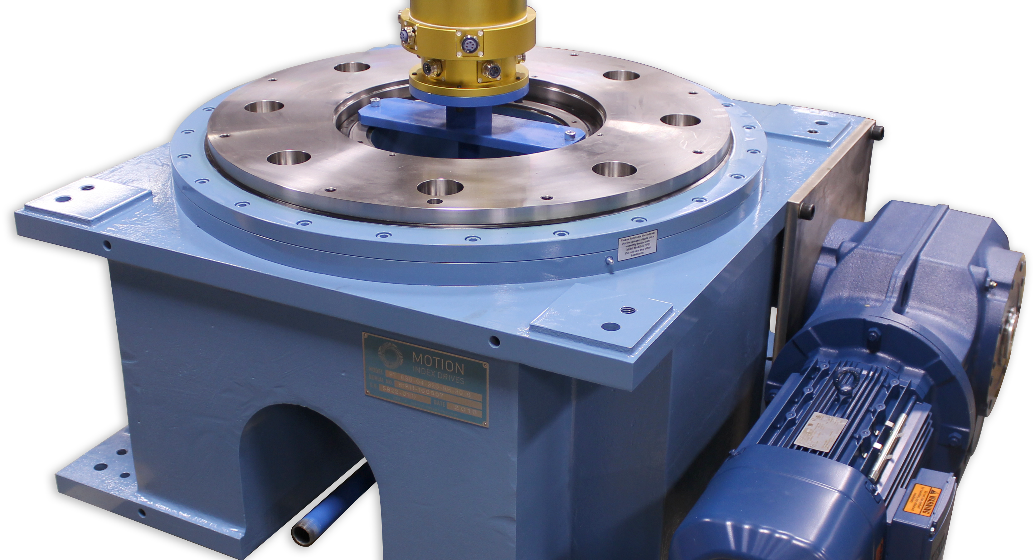
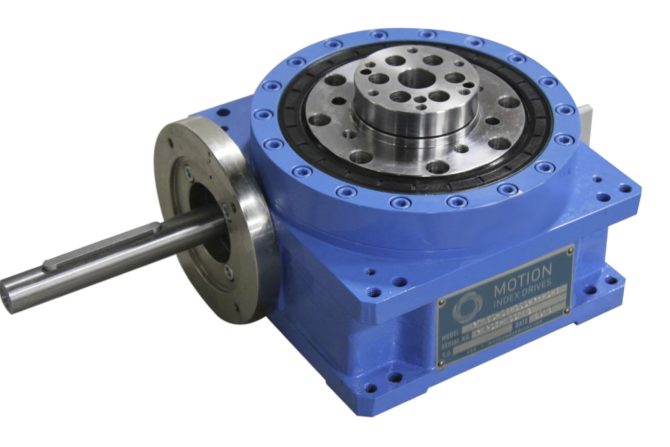
The Motion Index Drives RT Series Fixed Rotary Index Tables encompass a large range of sizes, ranging from our model RT100 up to our RT1250. In addition, special cam-driven devices can be custom made to order for your automation needs. RT Series Fixed Station Rotary Table are offered in a fixed number of stations or as a flexible turntable with a servo motor or standard AC brake motor with encoder. With the addition of Motion’s patented NANO Indexer Technology, the RT Series Fixed Station Rotary Table becomes the world’s most accurate barrel cam indexers.RT Series indexing tables are constructed with strength and reliability in mind. Robust design and components ensure this device will maintain precision in intense factory settings.
Among the many indexer manufacturers, what sets Pascal’s indexing table apart is undoubtedly its brakeless design, compact size, and durability. It has an ample amount of ports lending itself well to automation.
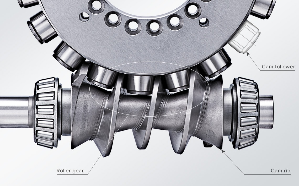
Pascal’s MDF index table operates with a 90° index 0.5 sec. Its unique rolling gear transmission is maintenance free and can operate with high index speed and accuracy for a long time unlike traditional worm gear. Traditional worm gear undergoes abrasive wear that can lead to backlash causing machining failure and degrading index accuracy.
Pascal’s high-performance rotary unions are integrated to enable clamp sensing and actuation but also provides a footprint 20% smaller than its competitors. Ideal for indexing large workpieces in compact machining centers, you will also achieve increased production capacity. As one example, our rotary indexing table can allow a machining center to increase their production capacity from 16 robodrill units to 24 units in the same amount of space.
The MDF index table has a total of 20 ports, lending itself well to automation. 18 of those ports can be used for hydraulic and air, while 2 are for coolant. A double acting cylinder with sensing can be used instead of a single cylinder, and its rotary joint accommodates a 7MPa pressure circuit.
Pascal is confident in the quality and reliability of our rotary indexers so much so that we use them in our own factories. That is also why these indexers are utilized in the factories of major automakers around the world.
Our product range includes single and multiple axes, tilt/rotating tables, and indexing and high-speed spindles. Additionally, we offer customized solution tables for customer requests or OEM projects.
Even for EDM machines that have been in use for decades, we will work with you to determine the ideal rotary indexing table and/or rotating/indexing spindle solution.
Our state-of-the-art rotary indexing tables and customizable reference and clamping systems provide endless application possibilities and highly efficient solutions.
In 1996, Precision Detroit Company established a relationship with WEISS GmbH. WEISS has been manufacturing high quality index tables for decades and is the leading automation component manufacturer in Europe today.
In August, 2007, WEISS GmbH established WEISS North America, Inc. as a wholly-owned subsidiary. On September 30, 2007, WEISS North America, Inc. acquired the assets of Precision Detroit Company, Inc. relative to its PDC Geneva Motion index tables and its network of sales representatives throughout the U.S. and Canada.
Today, WEISS North America is not only a rotary table manufacturer but your complete automation manufacturer and solutions partner. WEISS has decades of expertise in providing automation, drive and control solutions to industrial markets. WEISS offers industry-specific, cost-effective and efficient technology solutions to help you maximize your efficiency, increase your productivity and achieve optimal system performance. We understand that your application has unique processes and specific requirements and we work closely with you to develop the perfect automation solution for your particular needs.
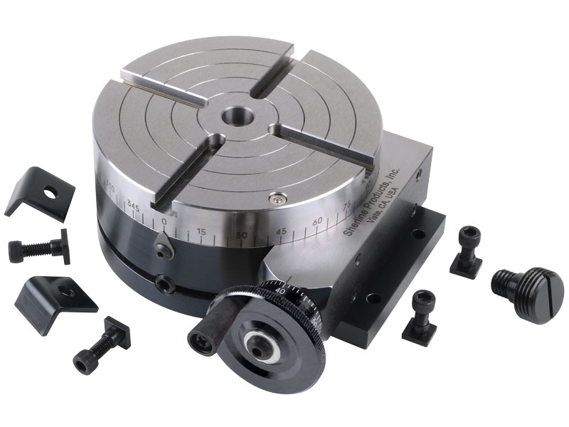
Sherline has taken their accurate and reliable 4″ rotary table into the 21st century with the addition of Computer Numeric Control. Clock-makers or anyone with a need to cut gears or other complicated radially symmetrical patterns will find this accessory takes all the headaches out of repetitive indexing operations.
The rotary table comes with clamps and T-nuts for attaching it to the T-slots of a Sherline mill table. In addition, there are two options available for mounting the table in the vertical position or at other angles:
Right-Angle Attachment—This plate holds the table in the vertical position with a center height of 2.7″. A right-angle tailstock is also available to support long stock held on center in the rotary table.
Tilting-Angle Table—This table holds the rotary table and can be fixed at any angle from 0° to 90°. In the 90° position, the rotary table center is also at the 2.7″ height, which allows the right-angle tailstock to be used with it.
After entering the number of steps per revolution (or the number of degrees per step) on a simple numeric keypad, the table advances quickly and precisely to the next position at the touch of a single advance key. If an error is made, previous positions can be accurately recalled by hitting another button. Basic resolution is 28,800 steps per revolution, ±0.006° per step. This allows the accurate machining of items like gears with odd numbers of teeth. Computations are made internally to a high degree of accuracy to avoid cumulative errors.
This invention relates generally to rotary tables. More particularly, the present invention relates to a rotary indexing table utilizing an AC induction motor with a high-resolution positional feedback device.
Rotary tables, such as rotary indexing tables, are well-known for the accurate positioning of work pieces at work stations for automated operations. Rotary indexing tables typically have a table and an indexer assembly that rotates the table through a predetermined angle for positioning work pieces for sequential automated operations.
Rotary indexing tables have been successfully employed in the field of automated assembly for work stations including pick and place devices, feeder bowls, visual inspections, label applicators, robot arms, adhesive applicators, laser machining and other automated assembly processes. Rotary indexing tables are further well-known in the fields of machining for the accurate positioning of work pieces to receive drilling, boring, tapping, CNC machining, facing, grinding, and other types of machining processes. Other uses for rotary indexing tables include the accurate positioning of work pieces for coating, sterilizing, cleaning, testing and calibrating.
As described in U.S. Pat. No. 5,950,503, rotary indexing tables have also been used in the decorating field for screen printing, hot stamping, pad printing, ink jet printing, impact marking, laser marking, spray painting and other decorative processes. For example, rotary indexing tables are currently employed for multi-color screen printing onto work pieces such as CD"s, credit cards, key fobs, etc. Typically, a rotary indexing table supports multiple, equidistantly positioned fixtures. The fixtures receive and support the work pieces during the printing operations. At a first work station, a work piece is automatically positioned onto the fixture. The table then rotates through a precise angle or distance to position the work piece under a first screen printing apparatus. After the printing is completed, the table rotates through the same angle again to position the work piece for receiving a second overlaying screen print image. The indexing process continues until the work piece has received all the required layers of screen printing and is removed from the fixture at a final work station.
With the need for very precise machining and close tolerances in manufacture, rotary indexing tables have had to be much more precise and provide more through-put in order for the industry to remain competitive. Rotary indexing tables, for example, may be required to move through a complex set of rotary profiles such as continuous rotation, indexing with a dwell time, oscillation, variable speed or reverse direction. It would be advantageous to have an assembly capable of all these motions while maintaining precision. In addition, with the advent of robotics these assemblies are required to place a work piece at various work angles relative to the work station to provide access from automated operational equipment.
Typically, prior art rotary indexing tables, also known as turntables, are centrally driven and work is performed at the periphery of the table. Alternately, when tables are driven on their outside diameter, the drive mechanism tends to be outside the periphery of the table and thus impedes use of the assembly in various angles and in operations where space is at a premium.
Most prior art rotary indexing tables are driven by cams or geneva mechanisms through a speed reducer and electric motor. Rotary indexing tables of this type suffer from various drawbacks including a fixed number of index positions, the inability to provide continuous rotation and the inability to be programmed.
Another prior art method of driving a rotary indexing table utilizes a ring gear and pinion arrangement powered with a speed reducer and electric motor. This method, however, also suffers from a variety of drawbacks. For instance, the use of a ring gear and pinion arrangement has a lower precision due to backlash. Also, such arrangements are very costly.
A third prior art method of driving a rotary indexing table is through the use of a servomotor configured to drive a cam or pinion gear. The use of a servomotor is costly and also requires a large number of mechanical components. Furthermore, servomotors usually require a load-to-motor inertia mismatch that is very low, such as 10 to 1. If the load-to-motor inertia mismatch exceeds this requirement, the result is instability and poor performance.
A final prior art method for driving a rotary indexing table is the use of a low speed direct drive permanent magnet motor. Such direct drive permanent magnet motors, however, are very expensive. Furthermore, the bearing loads of such motors limit the use of overhung loads on the tooling ring.
Accordingly, a need exists for a rotary indexing table with a drive mechanism that is of low cost while still providing high precision. A further need exists for a rotary indexing table with a simplified design including few moving parts so as to reduce backlash. A final need exits for a drive mechanism for a rotary indexing table that provides accurate positioning and smooth motion in the presence of very high inertial loads.
The present invention is a rotary indexing table driven by an induction motor. The rotary indexing table includes a rotatable work supporting platform, an AC induction motor including a motor shaft coupled to the rotatable work supporting platform; and a controller operatively coupled to the AC induction motor. The AC induction motor is equipped with a high resolution positional feedback device. The high-resolution positional feedback device may be an encoder or a resolver. The controller is configured to drive the AC induction motor in a direct drive manner. The high-resolution positional feedback device is operatively coupled to the controller, and the controller is configured to filter a signal provided by the high-resolution positional feedback device. The signal provided by the high-resolution positional feedback device may be a square wave or a sine wave.
The present invention is further directed to a rotary indexing table for supporting workpieces and moving the workpieces through a plurality of positions. The rotary indexing table comprises a rotatable, substantially planar, circular work supporting platform; a directly driven AC induction motor including a motor shaft coupled to the rotatable work supporting platform and a high resolution positional feedback device; and a controller operatively coupled to the AC induction motor and high-resolution positional feedback device. The controller is configured to filter a signal provided by the high-resolution positional feedback device.
The present invention is further directed to a method of precisely driving and positioning a rotary indexing table. The method includes the steps of providing a rotary indexing table including a rotatable work supporting platform; an AC induction motor including a motor shaft coupled to the rotatable work supporting platform and a high-resolution positional feedback device; and a controller operatively coupled to the AC induction motor. Next, the rotatable work supporting platform is driven using the AC induction motor and the high-resolution positional feedback device. Then a feedback signal is provided by the high-resolution positional feedback device, and the controller filters the feedback signal to produce a filtered signal. Finally, the AC induction motor is controlled to position the rotatable work supporting platform based on the filtered signal.
FIG. 1 is a top plan view of a rotary indexing table driven by an AC induction motor with a high-resolution positional feedback device in accordance with the present invention;
FIG. 2 is a side plan view of the rotary indexing table driven by an AC induction motor with a high-resolution positional feedback device in accordance with the present invention;
With reference to FIGS. 1-3, a rotary indexing table 1 includes a rotatable work supporting platform 3. Rotatable work supporting platform 3 is used to support work pieces, tooling, fixtures and the like for positioning as is known in the art. Rotatable work supporting platform 3 is rotationally mounted to a drive hub 5, which is in turn coupled to a drive end 7 of a motor shaft of an AC induction motor 9. Rotary indexing table 1 is also configured to include a bearing 11 secured by a flange mount bearing plate 13. Bearing 11 allows for smooth rotation of work supporting platform 3.
The use of AC induction motor 9 is advantageous because construction costs are relatively low compared with other types of motors, and AC induction motors are very reliable. In general, an AC induction motor includes a stator and a rotor. In operation, a rotating magnetic field is generated in the stator, which induces a magnetic field in the rotor. The two fields interact and cause the rotor to turn. To obtain maximum interaction between the fields, a very small air gap is provided between the rotor and stator. The speed of the rotor depends upon the torque requirements of the load. The bigger the load, the stronger the turning force needed to rotate the rotor. The turning force can increase only if a rotor-induced electromagnetic field increases. This electromagnetic field can increase only if the magnetic field cuts through the rotor at a faster rate. To increase the relative speed between the field and rotor, the rotor must slow down. Therefore, for heavier loads the induction motor turns slower than for lighter loads. Furthermore, AC induction motor 9 may be directly driven. This is advantageous because the use of a directly driven induction motor eliminates the need for gearing or belting thereby simplifying the design and reducing backlash. Furthermore, the elimination of gearing and belting also allows the motor to provide stable performance even in the presence of large inertial loads.
Rotary indexing table 1 further includes a high-resolution feedback device 15 coupled to the opposite end 16 of the motor shaft using a mounting plate 17 and an adapter shaft 19. High-resolution positional feedback device 15 may be an encoder, a resolver or the like. The resolution of high-resolution positional feedback device 15 is desirably between 1,000,000 and 5,000,000 counts per revolution allowing the device to more accurately represent the actual speed of AC induction motor 9. A controller 21 is operatively coupled to AC induction motor 9 and high-resolution positional feedback device 15. Controller 21 may be coupled to AC induction motor 9 and high-resolution positional feedback device 15 by an electrical connection, a wireless connection or any other suitable connection means. Controller 21 is configured to include feedback signal filtering capabilities.
The combination of high-resolution positional feedback device 15 with the process of filtering the high-resolution positional feedback signal with controller 21 allows rotary indexing table 1 to run smoothly with a very high degree of accuracy. First, the use of high-resolution positional feedback device 15 is critical to the operation of rotary indexing table 1. It provides the required accuracy and fine resolution feedback required to properly move and position rotary indexing table 1. A high-resolution feedback signal reduces speed feedback ripple by allowing controller 21 to more accurately reflect the actual speed of AC induction motor 9. The high-resolution feedback signal may be a square-wave, a sine wave or the like. Next, it is important that controller 21 is configured to include filtering capabilities. By filtering the high-resolution feedback signal, an even smoother feedback signal is created, which minimizes or eliminates erratic motion, improves stability and allows very high load-to-motor inertia mismatches.
In many applications, the inertial load of rotary indexing table 1 may be in excess of 100 times the motor inertia. In order to achieve accurate positioning and smooth motion given such high inertial loads, controller 21 must operate with very high gain. In other words, controller 21 must be capable of providing large corrections in position, speed and torque for small differences between a commanded and actual position, speed and torque. If these large corrections are not provided, stability problems arise.
While the previous embodiment has been described in terms of a directly driven rotary table, the present invention may also be driven through the use of gearing, belting or any other suitable means. With reference to FIGS. 4aand 4b, a second embodiment of a rotary indexing table 40 with an open center driven by an AC induction motor 41 and a gear-to-gear drive 42. Rotary indexing table 40 further includes a rotatable work supporting platform 43 used to support work pieces, tooling, fixtures and the like for positioning as is known in the art. Gear-to-gear drive 42 includes pinion gear 44 and a main gear 45. Pinion gear 44 is coupled to a drive end of a motor shaft of AC induction motor 41. A drive force is provided by AC induction motor 41 to pinion gear 44 thereby causing main gear 45 to rotate. The rotation of main gear 45 provides rotation to rotatable work support platform 43.
Rotary indexing table 40 further includes a high-resolution positional feedback device 46 coupled to the opposite end of the motor shaft of AC induction motor 41 using a mounting plate 47. A controller 48 is operatively coupled to AC induction motor 41 and high-resolution positional feedback device 46. Controller 48 may be coupled to AC induction motor 41 and high-resolution positional feedback device 46 by an electrical connection, a wireless connection or any other suitable connection means. As discussed above, controller 48 is configured to include feedback signal filtering capabilities.
The combination of high-resolution positional feedback device 46 with the process of filtering the high-resolution positional feedback signal with controller 48 allows rotary indexing table 40 to run smoothly with a very high degree of accuracy as discussed in detail above reference to FIGS. 1-3.
With reference to FIGS. 5aand 5b, a third embodiment of a rotary indexing table 50 with an open center is driven by an AC induction motor 51 and a belt drive 52. Rotary indexing table 50 further includes a rotatable work supporting platform 53 used to support work pieces, tooling, fixtures and the like for positioning as is known in the art. Belt drive 52 includes a toothed pulley 54, a belt 55 and a main pulley 56. Toothed pulley 54 is coupled to a drive end of a motor shaft of AC induction motor 51. A drive force is provided by AC induction motor 51 to toothed pulley 54 thereby causing force to be exerted on belt 55 causing main pulley 56 to rotate. The rotation of main pulley 56 provides rotation to rotatable work support platform 53.
Rotary indexing table 50 further includes a high-resolution positional feedback device 57 coupled to the opposite end of the motor shaft of AC induction motor 51 using a mounting plate 58. A controller 59 is operatively coupled to AC induction motor 51 and high-resolution positional feedback device 57. Controller 59 may be coupled to AC induction motor 51 and high-resolution positional feedback device 57 by an electrical connection, a wireless connection or any other suitable connection means. As discussed above, controller 59 is configured to include feedback signal filtering capabilities.
The combination of high-resolution positional feedback device 57 with the process of filtering the high-resolution positional feedback signal with controller 59 allows rotary indexing table 50 to run smoothly with a very high degree of accuracy as discussed in detail above with reference to FIGS. 1-3.
With reference to FIGS. 6aand 6b, a final embodiment of a rotary indexing table 60 is driven by an AC induction motor 61 and a gearhead 62. Rotary indexing table 60 further includes a rotatable work supporting platform 63 used to support work pieces, tooling, fixtures and the like for positioning as is known in the art. Gearhead 62 is coupled at a first end to rotatable work supporting platform 63 and at a second end to a drive end of a motor shaft of AC induction motor 61. A drive force is provided by AC induction motor 61 to gearhead 62 thereby causing force to be exerted on rotatable work support platform 63 causing it to rotate.
Rotary indexing table 60 further includes a high-resolution positional feedback device 64 coupled to the opposite end of the motor shaft of AC induction motor 61 using a mounting plate 65. A controller 66 is operatively coupled to AC induction motor 61 and high-resolution positional feedback device 64. Controller 66 may be coupled to AC induction motor 61 and high-resolution positional feedback device 64 by an electrical connection, a wireless connection or any other suitable connection means. As discussed above, controller 66 is configured to include feedback signal filtering capabilities.
The combination of high-resolution positional feedback device 64 with the process of filtering the high-resolution positional feedback signal with controller 66 allows rotary indexing table 60 to run smoothly with a very high degree of accuracy as discussed in detail above with reference to FIGS. 1-3.

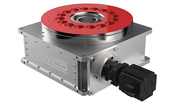
Rotary indexing table use is widespread in automated assembly machinery and selecting the proper mechanism is essential for both maximizing performance and minimizing the cost of this critical component. This how-to-guide will explore two common devices that can be used for rotary indexing and give advice for proper selection. These two popular devices are cam indexing drives and servo rotary tables.
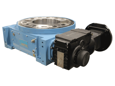
Cam indexers are a ubiquitous mechanism that have been used for rotary tables for many decades. They are a great fit for applications that will always index the same angle and that require high-precision positioning at a very reasonable cost. A cam indexer uses a mechanical cam to provide the motion control to position the load. A mathematical motion curve is machined onto the cam that provides extremely smooth and repeatable motion.
A cam indexer has two main modes of operation. One mode is referred to as “Cycle-on-Demand”. This indicates that the camshaft will be cycled one revolution at a time to advance the output one position at a time. This is typically achieved by using an inexpensive camshaft sensor package to detect camshaft position and a VFD to stop and start the motor. The camshaft dwell period offers a wide window for the camshaft to stop without affecting the position of the output. To cycle the indexer, a PLC gives a command to the VFD to accelerate the drive motor to a preset speed, the cam rotates one revolution indexing the output, a sensor sends an in-position signal to the PLC, and the PLC signals the VFD to stop the camshaft during the cam dwell position. The table will be in the dwell position for however long is necessary to complete the work at each station. The dwell time can range from a fraction of a second to several minutes or hours depending on the application. This combination allows very accurate positioning with an inexpensive drive system.
A cam indexer can also be run in a more traditional “Continuous” mode where the camshaft spins at a constant speed and the indexing and dwell time is controlled solely by the cam motion profile. Continuous mode is useful when other equipment will be mechanically synchronized with the camshaft timing or when the indexer needs to run at cycle rates faster than a motor can be stopped and started. A continuous indexer can run at rates in excess of 1,000 cpm. The limitation of continuous mode is that it may be impossible to machine a cam that requires a quick indexing motion followed by a long dwell time.
A fully programmable servo rotary table is another common option. There are two specific cases where a servo rotary table is advantageous. The first is when a flexible motion pattern is required. An example is two different products being run on one machine that each require different indexing patterns. The other situation that suits a servo indexer is when extremely fast positioning is required followed by a long dwell period. A cycle-on-demand cam indexer is limited by the need to accelerate the camshaft up to speed during the dwell period before output motion is started. There are practical limitations to how fast the camshaft can be accelerated so there will be a delay before motion is started. With a servo rotary table, the output rotates as soon as the servomotor starts moving. A practical example would be a load being indexed 90 degrees in 0.25 seconds. This is not difficult for a continuous cam indexer or a zero-backlash servo indexer, but a cycle-on-demand cam indexer may struggle with that motion. For quick servo indexing applications, a preloaded gear reducer with zero-backlash is critical to achieving smooth indexing motions with minimal settling time. A zero-backlash RollerDrive mechanism would be an optimal choice to achieve accurate positioning with great dynamic response.
For either style of indexer, application information including moment of inertia, indexing angle, indexing time, and dwell time is required. A reputable manufacture should then be able to properly size the rotary table for the application.
A popular question that we hear is, “How do I size a motor for my application?” This post looks at an example Rotary Index Table application and provides the equations and considerations needed to make the appropriate motor selection.
First, consider your machine’s movement. In our sample case of a Rotary Index Table, an engineer will need to first define all relevant information that will be used later in the Torque calculation. Typical information we will need includes:
Since we want to define the required motor torque, we want to be sure that we are using values that pertain directly to the motor itself. If there is a gearbox in the system, we need to be sure to reflect the required values back to the motor. We will need to determine the acceleration torque, deceleration torque, constant torque, and any torque due to gravity on the system. For this exercise, we will assume the index table is in a horizontal position, so the torque due to gravity will be zero.
Once we know the angular acceleration of the motor, we need to calculate the inertia of the load connected to the motor. In this case, we can approximate the index table inertia using the formula for a solid cylinder.
The load on the index table must also be taken into account. If the load is distributed evenly over the indexed surface, we can add this load into table weight to calculate the inertia of the complete system. If the load is not distributed evenly, then a separate load inertia will need to be determined, Jload.
Depending on the design of the system, there may be a constant friction torque, Mfriction, which must also be accounted for in the motor sizing. The amount of this constant torque will be dependent on the friction coefficient of the system and the weight of the table and load. Again, if there is a speed reduction in the system we can reflect this back to the motor shaft.
Optimizing the motor sizing for an indexing application can be an iterative process. By calculating the peak requirements and rms torque of the application, the selection of the motor can be done with confidence to provide a reliable solution for the application (see Figure 7).

Description: Features to tilts between 0- 90 Degrees & can be locked at any position. Table diameter 100 mm Table is graduated 360 Degrees. Worm Gear Ratio -1:36, which means that the 1 handle rotation shall turn the table by 10 Degrees. Center Height in vertical position: 2-5/8" (66 mm approx) Hand wheel is graduated in divisions of 10 min & can be set to zero. Can be mounted both in Horizontal & vertical position. SUPPLIED WITH A SUITABLE SMALL 65 MM 3 JAWS SELF CENTEING CHUCK WITH BACK PLATE & FIXING T NUTS BOLTS. 65 mm 3 Jaws Self Centering Chuck M14 x 1 mounting Thread Back Plate also has M14 x 1 thread Spigot to mount the Chuck on it. Back Plate is drilled in a manner that it can be fitted both for 3 as well as 4 Slot Rotary Table. Suitable T -nuts are also supplied.
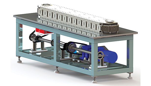
Flexible rotary tables and trunnion drives of the EDH series are drive modules for the realisation of flexible motion operations based on the use of freely programmable servo motors. Contrary to the s
Based on the approved construction principle of EXPERT-TÜNKERS standard rotary tables, the heavy-duty tables reach dimensions of diameters of up to 20 metres, with payloads of up to 150 tons. As a rul
Based on the approved construction principle of EXPERT-TÜNKERS standard rotary tables, the heavy-duty tables reach dimensions of diameters of up to 20 metres, with payloads of up to 150 tons. As a rul
The MI-indexing globoid tables with orthogonal shafts offer a movement rotating, intermittent, oscillating or flexible and respond to specific technical requirements.
Rotary drives assume high process responsibility as an elementary transport component of manufacture. Therefore, ultimate process reliability is the first maxim as to the development and design of EXP
The T-indexing globoid tables with orthogonal shafts offer a movement rotating, intermittent, oscillating or flexible and respond to specific technical requirements.
The TS-indexing drum tables with orthogonal shafts offer a movement rotating, intermittent, oscillating or flexible and respond to specific technical requirements.
6.1. North America Automated Rotary and Indexing Table Market Size (US$ Mn) and Volume (Million Units) Analysis & Forecast, by Configuration, 2017‒2031

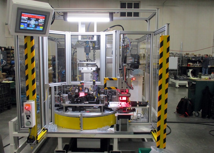
We combine rotary index tables with industrial automation systems so each task of your manufacturing process blends seamlessly into the next. For example, in the past we’ve created industrial automation systems that join rotary indexing machines with pick-and-place units for some of our clients. Contact us to see what we can do for you.
Rotary indexers are just one part of the equation when building a custom assembly cell. It’s important to remember the entire scope of the project and be cognizant that the rotary table should be able to move precise distances before stopping cleanly, with no backlash or wobbling. It needs to be balanced and capable of handling the tasks at hand.
Our automation experts have years of experience in consulting with our customers to create machines that suit their needs. We incorporate rotary tables from industry leaders like WEISS, Fibro, and Camco into our machines to create the perfect fusion of form and function. Our dedication to quality is unmatched in the world of custom machinery.
We seamlessly integrate rotary indexing tables into our automated machinery to provide you with custom solutions that work for your business. If you’re looking to take your manufacturing process to the next level, give the custom machine builders at Paramount Tool a call at (616) 582-5300 today. We’re always happy to answer any questions you may have about our rotary indexing machines or the machine building process as a whole. For a free quote, fill out our contact form and we’ll get back to you as soon as we can.


 8613371530291