
rotary table motor free sample
Our direct drive rotary tables provide high torque and are easy to integrate. They contain high-energy magnets in a simplified mechanical design and drive loads directly without the need for a transmission mechanism or gearbox. It allows customers to build them right into a drive system for flexible placement and integration with cooling pipes and cables, for example.
We supply a wide range of frameless motors, and our adjustable motors include an optical encoder, scale, bearing and housing. Given our selection, it can be challenging to choose the best direct drive motor for your project. Our engineers prefer to help you find the right rotary table for your requirements.
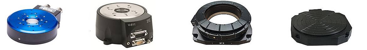
Our most popular rotary motor, the AXD series is characterized by a slim, compact "pancake" design with high peak and continuous torque despite the motor"s quite small form factor.Direct drive and brushless motor
The ACD series is a set of ironless rotary tables. This motor is cogging-free and features high-resolution optical encoder feedback and low speed variability. This permanent magnet motor is equally suited for either low or high speed applications.Zero cogging coreless motor
The ACW series features a cogless construction and lean design, with high-precision coding and ultra-precision bearings. Together, this results in our highest performing motor in terms of repeatability and smooth motion.Direct drive brushless motor
The ADR-A series is available with both low and high speed windings and is fully equipped with an encoder and bearing. This series has a high slot fill factor and generates very high torque.Direct drive brushless permanent magnet motor
The ADR-B range performs at a similar slot fill factor and torque density to the ADR-A range, but has a larger center hole compared to its equivalent.Direct drive brushless permanent magnet motor
Similar to the ACD series, the AXM series also features an ironless design and zero noise characteristics. This motor has a compact design, making it ideal for applications with specialized size requirements.Direct drive brushless permanent magnet motor
M-035 series high precision rotary tables rotation stages feature high resolution, excellent repeatability and minimum wobble. These high performance rotational positioning stages are equipped with double ball bearings for minimum backlash and high load capacity. Both the rotation stage platform and the scale ring (graduated in 2-degree increments) can be independently coarse positioned over 360 degrees and then be locked by screws.
The basic rotary table version, M-035.D0, is equipped with a DC servo motor drive providing a positioning range of ± 6.3 degrees. A set of limit switches eliminates the possibility of overtravel. For the highest precision and highest performance, high speed air bearing rotary tables are recommended.

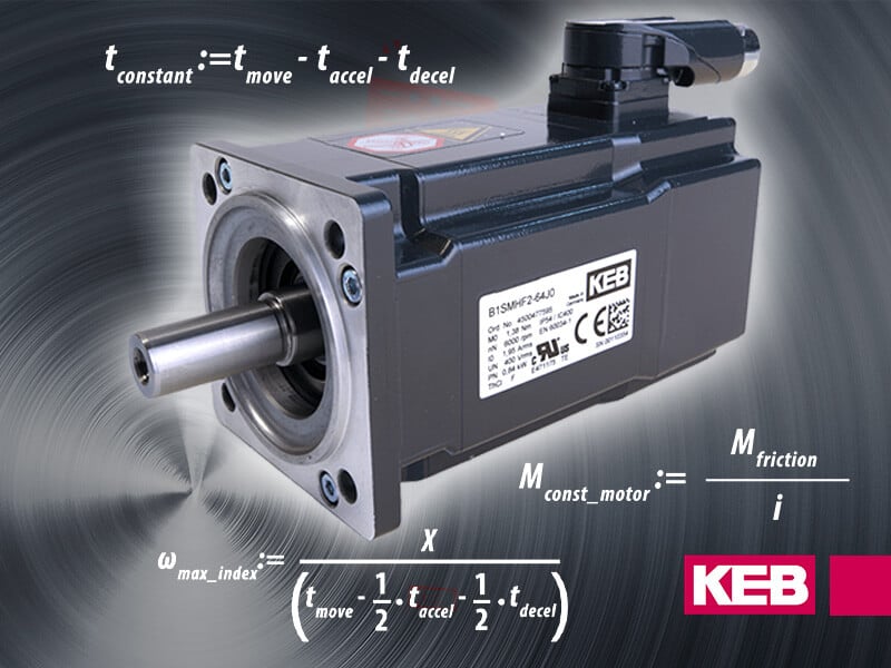
A popular question that we hear is, “How do I size a motor for my application?” This post looks at an example Rotary Index Table application and provides the equations and considerations needed to make the appropriate motor selection.
First, consider your machine’s movement. In our sample case of a Rotary Index Table, an engineer will need to first define all relevant information that will be used later in the Torque calculation. Typical information we will need includes:
The move profile can indicate a linear or rotational movement. The total area under the velocity curve defines the total move distance. Utilizing the data from the move profile will allow us to define the required maximum output speed of the motor.
Since we want to define the required motor torque, we want to be sure that we are using values that pertain directly to the motor itself. If there is a gearbox in the system, we need to be sure to reflect the required values back to the motor. We will need to determine the acceleration torque, deceleration torque, constant torque, and any torque due to gravity on the system. For this exercise, we will assume the index table is in a horizontal position, so the torque due to gravity will be zero.
Using the maximum angular velocity and deceleration times, we can calculate the angular acceleration, αaccel_motorand angular deceleration, αdecel_motor.
Once we know the angular acceleration of the motor, we need to calculate the inertia of the load connected to the motor. In this case, we can approximate the index table inertia using the formula for a solid cylinder.
The load on the index table must also be taken into account. If the load is distributed evenly over the indexed surface, we can add this load into table weight to calculate the inertia of the complete system. If the load is not distributed evenly, then a separate load inertia will need to be determined, Jload.
Now that we know our inertia and our acceleration and deceleration rate, we can determine the required torque. If known, we can add in the inertia of the motor, Jmotor, the gearbox, Jgearbox and a brake on the motor, Jbrake,if the system has a brake.
Depending on the design of the system, there may be a constant friction torque, Mfriction, which must also be accounted for in the motor sizing. The amount of this constant torque will be dependent on the friction coefficient of the system and the weight of the table and load. Again, if there is a speed reduction in the system we can reflect this back to the motor shaft.
Note that the friction torque helps to slow the system. This can be used to allow the time to decelerate the system to be reduced and the time to accelerate the system increased. This has the advantage of decreasing the peak torque requirement of the motor. If the application allows a faster deceleration time, this may allow the motor size to be reduced.
In addition to determining if the motor has sufficient torque to make the move as defined by the move profile, we must also verify the rms motor torque over the complete cycle is less than or equal to the rated torque of the motor. If the rms torque is higher than the rated torque of the motor, the motor may overheat.
Optimizing the motor sizing for an indexing application can be an iterative process. By calculating the peak requirements and rms torque of the application, the selection of the motor can be done with confidence to provide a reliable solution for the application (see Figure 7).
In our example, we would want to make a motor selection that offers rated torque above the calculated rms torque value across the needed speed range. Additionally, we would want to make sure the peak torque (red line) is more than the calculated maximum torque value.
Do you have questions about choosing the correct motor size and technology for your application? Contact a KEB Engineer today to discuss your machine design.
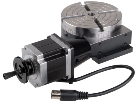
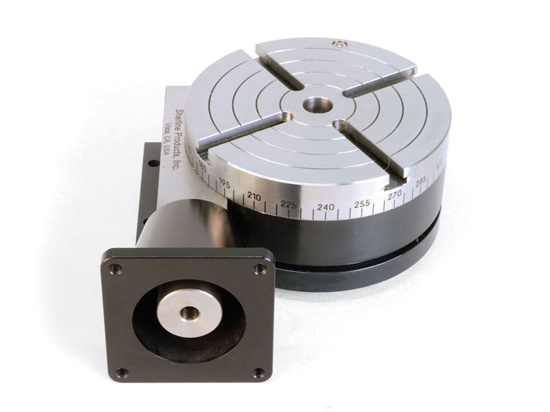
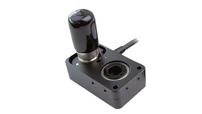
Sherline has taken its manual 4″ rotary table with reverse mount and applied a stepper motor mount with dampened coupling in place of the handwheel. The mount accepts a NEMA #23 frame size stepper motor for CNC control. This allows the table to be used as a 4th axis with CNC systems that have the capability to drive a rotary axis.
The reverse rotary table is perfect for using on the tilting angle table. The reverse mount allows access to the handwheel from the front of the machine (see photo below). If you used a standard rotary table in the previously described set-up the handwheel would be mounted facing the backside of the X-axis.
NOTE: When the worm housing is reversed to the opposite side, a clockwise rotation of the handwheel or stepper motor will result in a counter-clockwise rotation of the rotary table.
The rotary tables can hold more weight when they are not under a continuous load. Click on the Video tab above to see examples of different weights and uses for our rotary tables.
Sherline’s CNC driver box comes equipped with an A-axis output cable ready to drive a 4th rotary axis. This rotary table is all you need to turn your Sherline CNC mill into a 4-axis machine. Just plug the A-axis cable from the external driver box or the built-in driver box in your Sherline computer into the matching plug on the stepper motor. The EMC2 software is already set up to handle G-code for the A-axis, and numbers entered after the letter “A” in your code are interpreted in degrees.
The same end result can be obtained by ordering a CNC ready rotary table and a stepper motor and attaching the motor, but this single part number does the same thing, making it easier to order and saving you the trouble of installing the motor on the rotary table.

The DGII Series is a line of of products that combine a high rigidity hollow rotary table with an AlphaStep closed loop stepper motor and driver package. It retains the ease of use of a stepper motor, while also allowing for highly accurate positioning of large inertia loads.
AlphaStep products are stepper motor based hybrid motors with a unique hybrid control system combining the benefits of "open loop control" and "closed loop control".
By utilizing the high responsiveness of the stepper motor, moving a short distance for a short time is possible. The motors can execute commands without lag.
During positioning, the motor stops with its own holding force without hunting. Because of this, it is ideal for applications where the low rigidity of the mechanism requires absence of vibration upon stopping.
If an overload is applied continuously, an alarm signal is output. When the positioning is complete, and END signal is output. This ensures the same level of reliability as a servo motor.
To achieve rotary motion, Cross Company pairs a rotary table with a servo motor, drive and control to create a complete rotary actuation system. This allows greater flexibility for your rotary positioner because you’re not tied to just one or two positions. Some examples of rotary actuation that Cross Company has worked on recently include:Robotic cells which require precise rotary indexing for manufacturing stations
Cross Company’s Automation Group works with several different manufacturers of motors, drives and rotary tables. We work with you to understand your application and then we size and specify the best combination for your particular need. We have literally decades of experience working with rotary actuators, so we can specify a robust solution optimized for the application.
Cross is proud to represent the following manufacturers of rotary positioners:Parker:Worm gear-driven precision rotaries, manual stages and direct drive rotary servo motors which are suitable for light to medium industrial precision positioning
In virtually every industry, a right-sized rotary solution increases the throughput and efficiency of your process. By working with Cross Company, we can help reduce the risk of incorrectly sized and specified equipment, delivering a complete solution perfectly tailored to your application. Contact the experts at Cross to discuss your rotary positioning needs.

There is no theoretical limit to the speed of a linear engine because there is no contact. However, speed is typically limited by the mechanical bearings. For example, the maximum speed for linear control systems with rails and guide cars is usually limited to 5m/s. Therefore, the speed for linear motors in most applications is limited to 5m/s. The use of ceramic ball bearings allows speeds of up to 10m/s. By using air bearings, higher speeds can also be possible.
There is no length limit for linear motors. This is because the engine tracks can be connected to each other in sections. The linear rails can also be connected to each other. The linear scale for donor repatriation can be delivered in large lengths as well. Therefore, linear engine applications can be built up to 20m or even longer.
If the current is suddenly interrupted, a linear motor can move on under its own inertia, until it encounters the final attack or comes to a halt due to friction force. This is not usually a problem, but it can be a problem for some applications. It is possible to install a brake with the linear motor, which will be activated, when power interrupts. In this way, the engine can stop immediately. Such a brake is typically installed on the rails of the linear guidance.
Linear Motors can be used in cleanroom environments. In fact, many front-end semiconductor applications have linear motors in use. In wafer manufacturing plants, high-precision lithography machines, for example, use linear motors in XY positioning tables with very high accuracy (nanometer resolution) and submicron accuracy in cleanroom classes according to ISO 2.
The rotational inertia influences the inertia mismatch between the payload and motor, which in turn affects the servo system’s ability to control motion. While keeping the inertia mismatch below a 10:1 ratio is a good rule of thumb for applications using plug-and-play motors and drives, modern control systems can remain stable at far higher mismatches as long as you have no disturbances and are able to adjust the PID tuning. An SBR can easily be tuned for stable indexing at up to 200:1 and beyond.
Sample payloads are shown below with dotted lines representing one-inch thick aluminum plates of various outer diameters. This information can serve as a quick guide to controllable inertia ratios for different SBR and motor combinations. Other cases can be quickly assessed by mentally moving a dashed line downwards in proportion to your payload thickness. For example, if your table has a 12-inch diameter and 0.5-inch thickness, shift the 12-inch dashed line down by half to end the mismatch for a given house motor. Or, consider your actual payload inertia if known.

Ensure that your servo drive can handle the Nominal- and Peakcurrent of the Motor. An adjustment of the Speed and DC Bus Voltage can be done after consultation. The nominal data in this datasheet are based on an ambient/coolant temperature of 20°C.
Because the exact duty type depends also on the thermal connection of the motor, the embedded thermal monitoring system has to be analysed and attented. However, attention has to be payed that the temperature sensors do not show the exact temperature of the winding and this could be up to 20 K higher due to thermal capacities. Despite an electrical insulation towards the winding, you are only allowed to connect the sensors to your controller by using a galvanic separation in between.
A turbo among rotary tables – the new FIBRODYN DA direct driven rotary tables with torque motor are optimally suited for all handling and assembly applications that require the shortest indexing times and flexible positioning. Thanks to its measuring system directly in the rotary table axis, any position can be moved to with the highest precision. The slim design with its very space-saving, compact construction and its fitted boreholes makes it very easy to integrate the rotary tale into your system. FIBRODYN DA is also available as decentralized stand-alone solution with integrated control. In this version, it offers the ideal opportunity to save a separate external NC control to minimize the implementation and start-up costs and to realize small machines without complex peripherals. The rotary tables are lifetime lubricated and maintenance free.
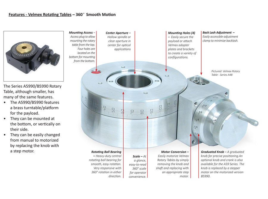
• A means to control the position of the carriage. This can be a crank and knob, a graduated knob, a micrometer head or a motor. On a Velmex Free Slide, position is controlled by the operator pushing the carriage into position.
Load maximum for the bottom or X slide must now be calculated including the weight of the Y slide and any components used to attach it to the X slide. The stage can be manually- or motor-driven.
An XY Table can also be comprised of 2 linear slides traveling in tandem on the X axis and 2 traveling in tandem on the Y axis. In this configuration the tandem slides affixed at the outside perimeter of the base plate and platform plate. Frequently this type of XY table will have an aperture in the center because the slides are attached at the perimeters of the base and platform plate.
Another form of elevating table uses a linear slide mounted on the Z axis to a base plate. The payload can be mounted directly to the carriage or it can be mounted on a L-shaped platform bracket which is in turn mounted to the carriage.
Load maximum for the bottom or X slide must now be calculated including the weight of the Z slide and any components used to attach it to the X slide. This is more than likely also going to be a cantilevered load. The stage can be manually- or motor-driven.
Load maximum for the base or X slide must now be calculated including the weight of the X slide and the weight of the Z slide and any components used to attach them to the other slides. The system can be manually- or motor-driven.
Rotary tables can be manually- or motor-driven. Large scale rotary tables are frequently found in CNC machining operations. They are also used in indexing or pan and tilt operations.

Many motion control applications use permanent magnet DC motors. Since it is easier to implement control systems using DC motors compared to AC motors, they are often used when speed, torque, or position needs to be controlled.
There are two types of commonly used DC motors: Brushed motors, and brushless motors (or BLDC motors). As their names imply, DC brushed motors have brushes, which are used to commutate the motor to cause it to spin. Brushless motors replace the mechanical commutation function with electronic control.
In many applications, either a brushed or brushless DC motor can be used. They function based on the same principles of attraction and repulsion between coils and permanent magnets. Both have advantages and disadvantages that may cause you to choose one over the other, depending on your application’s requirements.
DC motors use wound coils of wire to create a magnetic field. In a brushed motor, these coils are free to rotate to drive a shaft – they are the part of the motor that’s called the “rotor”. Usually the coils are wound around an iron core, though there are also brushed motors that are “coreless”, where the winding is self-supported.
The fixed part of the motor is called the “stator”. Permanent magnets are used to provide a stationary magnetic field. Normally these magnets are positioned on the inner surface of the stator, outside of the rotor.
Since there is some mechanical friction between the brushes and commutator – and since it is an electrical contact, it generally cannot be lubricated – there is mechanical wear of the brushes and commutator over the lifetime of the motor. This wear will eventually reach a point where the motor no longer functions. Many brushed motors – especially large ones – have replaceable brushes, typically made of carbon, which are designed to maintain good contact as the wear. These motors require periodic maintenance. Even with replaceable brushes, eventually the commutator also wears to the point that the motor must be replaced.
In cases where rotation is only needed in one direction, and speed or torque doesn’t need to be controlled, no drive electronics at all are required for a brushed motor. In applications like this, the DC voltage is simply switched on and off to make the motor run or stop. This is typical in low cost applications like motorized toys. If reversal is needed, it can be accomplished by using a double pole switch.
To facilitate control of speed, torque, and direction, an “H-bridge” composed of electronic switches - transistors, IGBTs, or MOSFETs - is used to allow the motor to be driven in either direction. This allows the voltage to be applied to the motor in either polarity, which makes the motor rotate in opposite directions. The motor speed or torque can be controlled by pulse width modulating one of the switches.
Brushless DC motors operate on the same principle of magnetic attraction and repulsion as brush motors, but they are constructed somewhat differently. Instead of a mechanical commutator and brushes, the magnetic field of the stator is rotated by using electronic commutation. This requires the use of active control electronics.
In a brushless motor, the rotor has permanent magnets affixed to it, and the stator has windings. Brushless motors can be constructed with the rotor on the inside, as shown above, or with the rotor on the outside of the windings (sometimes called an “outrunner” motor).
The number of windings used in a brushless motor is called the number of phases. Though brushless motors can be constructed with different numbers of phases, three phase brushless motors are the most common. An exception is small cooling fans that may use only one or two phases.
The three windings of a brushless motor are connected in either a “star” or a “delta” configuration. In either case, there are three wires connecting to the motor, and the drive technique and waveform is identical.
With three phases, motors can be constructed with different magnetic configurations, called poles. The simplest 3-phase motors have two poles: the rotor has only one pair of magnetic poles, one North and one South. Motors can also be built with more poles, which requires more magnetic sections in the rotor, and more windings in the stator. Higher pole counts can provide higher performance, though very high speeds are better accomplished with lower pole counts.
To drive a three phase brushless motor, each of the three phases needs to be able to be driven to either the input supply voltage or ground. To accomplish this, three “half bridge” drive circuits are used, each consisting of two switches. The switches can be bipolar transistors, IGBTs, or MOSFETs, depending on the voltage and current required.
There are a number of drive techniques that can be employed for three phase brushless motors. The simplest is called trapezoidal, block, or 120-degree commutation. Trapezoidal commutation is somewhat similar to the commutation method used in a DC brush motor. In this scheme, at any given time, one of the three phases is connected to ground, one is left open, and the other is driven to the supply voltage. If speed or torque control is needed, usually the phase connected to the supply is pulse width modulated. Since the phases are switched abruptly at each commutation point, while the rotor rotation is constant, there is some variation of torque (called torque ripple) as the motor rotates.
For higher performance, other commutation methods can be used. Sine, or 180-degree, commutation drives current thorough all three motor phases all of the time. The drive electronics generates a sinusoidal current though each phase, each shifted 120 degrees from the other. This drive technique minimizes torque ripple, as well as acoustic noise and vibration, and is often used for high performance or high efficiency drives.
Depending on your application, there are reasons why you might choose to use a brushless motor over a brushed motor. The following table summarizes the main advantages and disadvantages of each motor type:
As previously mentioned, one of the disadvantages of brushed motors is that there is mechanical wear of the brushes and commutator. Carbon brushes in particular are sacrificial, and in many motors they are designed to be replaced periodically as part of a maintenance program. The soft copper of the commutator is also slowly worn away by the brushes, and eventually reach a point where the motor will no longer operate. Since brushless motors have no moving contacts, they do not suffer from this wear.
Brushed motors rotational speed can be limited by the brushes and commutator, as well as the mass of the rotor. At very high speeds, the brush to commutator contact can become erratic, and brush arcing increases. Most brushed motors also use a core of laminated iron in the rotor, which gives them large rotational inertia. This limits the acceleration and deceleration rates of the motor. It is possible to build a brushless motor with very powerful rare earth magnets on the rotor, which minimizes the rotational inertia. Of course, that increases the cost.
The brushes and commutator form a kind of electrical switch. As the motor turns, the switches are being opened and closed, while significant current is flowing through the rotor windings, which are inductive. This results in arcing at the contacts. This generates a large amount of electrical noise, which can get coupled into sensitive circuits. Arcing can be somewhat mitigated by adding capacitors or RC snubbers across the brushes, but the instantaneous switching of the commutator always generates some electrical noise.
Brushed motors are “hard switched” – that is, current is abruptly moved from one winding to another. The torque generated varies over the rotation of the rotor as the windings get switched on and off. With a brushless motor, it is possible to control the winding currents in a way that gradually transitions current from one winding to another. This lowers torque ripple, which is a mechanical pulsation of energy onto the rotor. Torque ripple causes vibration and mechanical noise, especially at low rotor speeds.
Since brushless motors require more sophisticated electronics, the overall cost of a brushless drive is higher than that of a brush motor. Even though a brushless motor is simpler to manufacture than a brushed motor, since it lacks brushes and a commutator, brushed motor technology is very mature and manufacturing costs are low. This is changing as brushless motors become more popular, especially in high volume applications like automotive motors. Also, the cost of electronics, like microcontrollers, continues to decline, making brushless motors more attractive.
Due to declining costs and better performance, brushless motors are gaining in popularity in many applications. But there are still places where brushed motors make more sense.
Much can be learned by looking at the adoption of brushless motors in automobiles. As of 2020, most motors that are running whenever the car is running – things like pumps and fans – have moved from brushed motors to brushless motors for their increased reliability. The added cost of the motor and electronics more than makes up for the lower rate of field failures and decreased maintenance requirements.
On the other hand, motors that are operated infrequently – for example, motors that move power seats and power windows – have remained predominately brush motors. The reasoning is that the total run time over the life of the car is very small, and it is very unlikely that the motors will fail over the life of the car.
As the cost of brushless motors and their associated electronics continues to decrease, brushless motors are finding their way into applications that have traditionally been held by brushed motors. As another example from the automotive world, seat adjustment motors in high end card have been adopting brushless motors because they generate less acoustic noise.


 8613371530291