
4th and 5th axis rotary table free sample

A cookie is a small text file that a website saves on your computer or mobile device when you visit the site. It enables the website to remember your actions and preferences (such as login, language, font size and other display preferences) over a period of time, so you don’t have to keep re-entering them whenever you come back to the site or browse from one page to another.

Whether you use mills, presses or lathes, machine tools are often only as useful as the accessories that come with them. Take care of repair tasks and add extra functionality with the machine tools accessories at Alibaba.com. If you need new 5 axis rotary table or are seeking to replenish your component stocks, our wholesale store is the ideal place to look. We stock accessories for every type of machine tool, with multiple options in most cases. So add resilience to your operations and be ready for any production challenge with the machine tools accessories in our store.
Machine tools come in all shapes and sizes, and so do the accessories that make them tick. For instance, CNC and manual lathes can be customized with jaw chucks, shanks, woodworking knives, drill chucks, rotary chucks, clamps, and turning tools. Add brushes and sanding discs, and turn your machine tool into a multi-purpose machining center. Add a range of cutting tools to milling machines, pick the right drum sanders for your drills, or add a lathe dog to make turning much easier. There are accessories for hydraulic presses, add-ons like drag chains, and many other machine tools accessories. And if you need replacement 5 axis rotary table, Alibaba has everything you need.
Our machine tools catalog is packed with accessories. Search the listings for your preferred tool and zero in on accessories that can enhance its functionality. From control handles to tool holders, thread holders and saw blades, the whole panorama of machine tools accessories is here and ready to order. There"s no better way to add extra stocks and renovate machinery when the time comes. When new 5 axis rotary table are required, head to the Alibaba wholesale store and give your machinery a new lease of life.

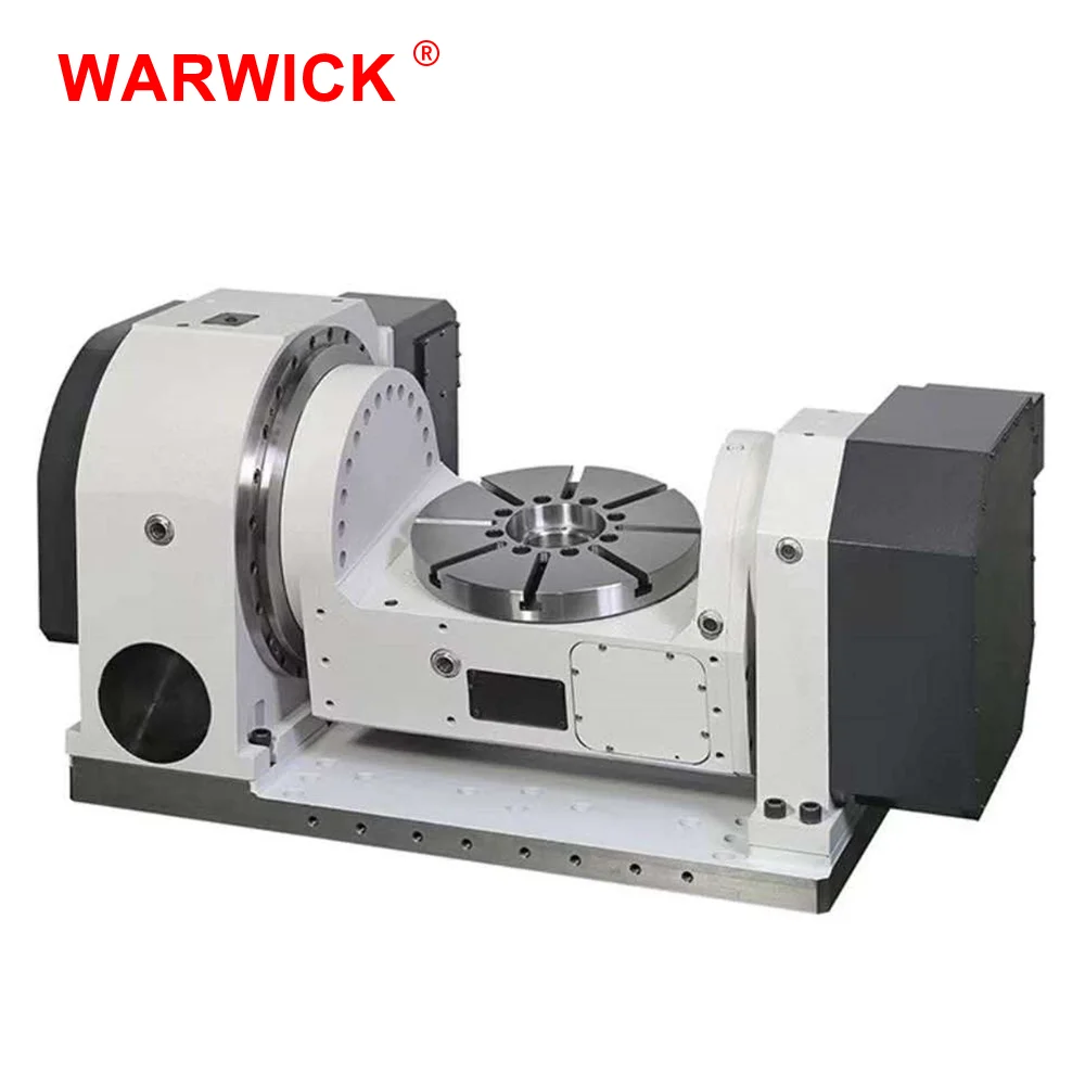
The robust geared rotary tables of the 500 series are extremely flexible to use and, thanks to the combiFLEX® modular system, can be converted or extended at any time to meet new machining tasks. The rotary tables are not only suitable for positioning operation, but can also be used for short simultaneous machining operations. The preloaded gear and the powerful bearings allow high long-term accuracies as well as large spindle loads. The maximum clamping force of up to 7,000 Nm leaves hardly anything to be desired.

Note: Post Processors for Fusion 360 and HSM CAM products are Javascript text files with a CPS text extension. The CPS files can be opened in any text editor (Notepad, TextEdit, Brackets, Notepad++...) to perform edits. After a CPS file/post processor is edited, it will need to be saved and added into the CAM program using the installation resources ("See Also" section of this article). Post processors can be downloaded from the Autodesk Post Processor Library.
To enable the 4th and 5th axis code, set the right machine configuration for the ABC axis for the specific machine being used. The machine configuration can be found in the onOpen() function:
Range: Specifies the angular range for the axis in degrees as a 2-element array ("[-120, 120]"). You can also specify a single number to create an axis for an aggregate.
Resolution: Specifies the resolution. In degrees for rotational actuator. The default is 0. Note: If there"s only need for a 4 axis setup, delete the other axis beginning with "var bAxis” and “var cAxis” or disable them by typing two slashes “//” in front of the line that needs to be disabled.
This line creates a new machine configuration as defined previously by using the given variables for each axis (in that case: aAxis, cAxis). Only use the variables inside the parenthesis. If an axis has been removed or disabled earlier for a 4 axis machine setup, remember to remove the disabled axis variable here as well.
APO/FPO, Afghanistan, Africa, Alaska/Hawaii, Albania, American Samoa, Andorra, Armenia, Azerbaijan Republic, Bahrain, Bangladesh, Belarus, Bermuda, Bhutan, Bosnia and Herzegovina, Brunei Darussalam, Cambodia, Central America and Caribbean, Cook Islands, Cyprus, Fiji, French Polynesia, Georgia, Gibraltar, Greenland, Guam, Guernsey, Iceland, India, Indonesia, Iraq, Jersey, Jordan, Kazakhstan, Kiribati, Kuwait, Kyrgyzstan, Laos, Lebanon, Liechtenstein, Macau, Macedonia, Malaysia, Maldives, Malta, Marshall Islands, Micronesia, Moldova, Monaco, Mongolia, Montenegro, Nauru, Nepal, New Caledonia, New Zealand, Niue, Oman, Pakistan, Palau, Papua New Guinea, Philippines, Qatar, Russian Federation, Saint Pierre and Miquelon, San Marino, Serbia, Solomon Islands, South America, Sri Lanka, Svalbard and Jan Mayen, Tajikistan, Tonga, Turkey, Turkmenistan, Tuvalu, US Protectorates, Ukraine, Uzbekistan, Vanuatu, Vatican City State, Wallis and Futuna, Western Samoa, Yemen
The fastest way to increase the productivity of your Haas mill is to add a Haas single or dual-axis rotary product. You can reduce or totally eliminate multiple setups, and easily handle machining multi-sided parts.
With a full line of Haas rotary products, including many specialised units designed for maximum productivity, Haas continues to lead the way to higher productivity through automation.
All Haas rotary products are designed to integrate seamlessly with the control on your Haas mill. This means true simultaneous 4-axis or 5-axis motion, synchronized with the axes of your mill. Rotary setup is a simple plug-and-play process through the Haas Control, with on-screen instructions, and diagrams that are intuitive and easy to use. It’s possible to install a Haas rotary on other makes of mill as we also offer the Haas Servo Control. Activated by a single M-code, the Servo Control is easy to set up, and fully programmable.
Adding a rotary axis to your CNC mill is the fastest way to boost throughput and increase accuracy. Because Haas began as a rotary table manufacturer in the 1980s, we are able to provide the simplest and most cost-effective entry into 4-axis and 5-axis machining available.
Going from 3-axis machining to 4-axis and 5-axis machining can be intimidating. This short video shows how easy it is to transition from basic 3-axis milling to full 5-axis design and production.
Haas offers a wide selection workholding solutions for your 4-axis and 5-axis clamping needs, from compact air-collet closers to quick-change fixture plates to manual scroll chucks.
Constructed of heavy-duty materials and designed for dependable day-in, day-out operation, Haas rotary products are the benchmark by which all others are measured. We manufacture all critical components in-house at our state-of-the-art California facility. At the core of every Haas rotary table is a large-diameter, aluminium-bronze worm gear meshing with a ground alloy steel worm (hardened to 60 Rc) submerged in a synthetic oil bath.
To ensure indexing accuracy, we cut the worm gear while it’s attached to the spindle, rather than assembling the finished worm gear to the spindle, as other manufacturers do. Each assembled spindle is trammed-in on a CNC gear hobber to a maximum 2-micron runout, and then the worm gear is precision cut. This guarantees the utmost concentricity between the large-diameter ball bearings and the worm gear, ensuring many years of smooth, extremely accurate, and bind-free operation.

It’s true that less than 10% of machined parts require simultaneous 5-axis movement. Which means that more than 90% of the parts machined in a typical job shop would not benefit from expensive, complicated, full 5-axis contouring; but that doesn’t mean your shop wouldn’t benefit from simple, affordable, 5-axis indexing capability. Work platter: Available in 6.75" diameter, T-sloted platters with drilled and tapped holes to accept Raptor or any brand work-holding, vises, fixtures, chucks, etc. Also available in dual-spindle system for increased efficiencies by cutting the number of tool changes in half.
1. QuindexPneumatic 5th Axis Bolt-on kit:Easily bolts-up to your existing true 4th or semi-4th axis rotary table. Shop air drives the spindle 90 degrees up against hard stops as well as provides 300 lbs. of brake force to allow for heavy cuts. A simple M-code or relay closure triggers indexing. This is the most cost-effective option to start 5-sided machining and is designed to mount to most other brands of rotary tables. (As well as ours of course!)
2. Quindex Semi 4th and Pneumatic 5th Axis Package:This package is everything you need to turn your 3-axis machine into a 5-axis workhorse.This package comes completely assembled and mounted on a subplate for a fast, accurate set-ups.
•Index Designs true 4th axis rotary table with Quindex 5th axis head, outboard support all mounted on a subplate. Call or email for quote on your specific machine. Please provide year, machine and control
brand with model number and if machine is 4th axis ready including amplifier. For example: 2015, XYZ machine with Fanuc OiMF control, not 4th axis ready, no amp.
•Dual Quindex heads on any of the above configurations. Increase your output and cut your tool changes in half by machining two parts in one set-up. Add $4995.
All prices and specifications subject to change without notice. Freight, rigging, state & local taxes, vendor installation charges, and other dealer installed accessories are not included. All prices are in U.S. dollars.
This website is using a security service to protect itself from online attacks. The action you just performed triggered the security solution. There are several actions that could trigger this block including submitting a certain word or phrase, a SQL command or malformed data.
So, there are a couple different ways to set up the variables in this post. You can either read the "shifts" from the Miscellaneous Real Numbers (set in each operation, using MR7, MR8, MR9), or you can use a set of "global" shifts, where you are shifting the location of the Secondary rotary axis.
Set your "offsets" in the "saxisx", "saxisy", and "saxisz" variables. The critical ones here are going to be "X" and "Z". These will "shift" your part coordinates around as the B Axis is rotated, since the Face of the C-Axis is not coincident with the center of B-Axis rotation.
Once you enter the shift values, you may need to play around with the "r_intersect" variable. Try leaving it "off", and testing your output. Then try turning it "on" (set to "1") and post again.
When you start setting this up, draw up everything as it exists in the "real world". Create a test part that isn"t some stupid crazy impeller. Instead, use like a 2" x 2" block, maybe 6" long, and program a simple contour on the "top" face (face that is pointing towards the spindle at B0), and then create contours on the Front, Right, Back, and Left faces (retaliative to your "top" face). Make your test part something simple, that is easy to measure with hand tools on the machine.
Your rotary unit is repaired, reassembled and run in for 10 hours. It is then re-inspected, all final adjustments and calibrations are performed to the original manufactures specification.
The original Fadal rotary heads are still one of the best overall designed attachments for the Fadal machine. While there are many imported rotary heads that might "look good" on the outside, it"s the inside that really counts. The simple fact is the Fadal rotary tables were specifically designed to take a crash and keep on working.
Many different rotary heads were made throughout the years of production. A 4th or 5th rotary axis was one of the most popular machine options. In the early 90"s we started shipping all machines "4th axis ready" which means the machine has all the wiring necessary. You basically only needed an amplifier and a axis controller card with software. Contact us if you thinking of adding a 4th axis, we offer all the necessary components.
As you"ll see below, we are the most qualified to repair your rotary table. Having been there from the beginning, we know exactly what your table needs to bring it up to original specifications.
The very first rotary table sold that was sold on the VMC45 in 1981. It was designed and manufactured by Fadal for the VMC45, it never realized full production after production the VMC45 was stopped.
Troyke Mfg. Co. -Afterwards, with the introduction of the VMC40 in 1984, we began offering the TROYKE rotary products as a 4th axis option. The table had an interesting full contact bearing surface using Turcite between the faceplate and the casting with radial bearings support for the faceplate spindle. Few of theses units still remain in the field today. If needed, we can provide complete service for these units.
Soon after 1987, we started adapting many of the popular Japanese rotary tables. Some customers would send us their tables and we adapt our motors and 4th axis interface to them. Eventually we started adding the Tsudakoma, Tecnara and Nikken rotary tables as a direct option to all machines
TR65 - The TR65 (Tilt/Rotate, 6.5" dia. faceplate) had a unique clutch system build into the trunion for the B-axis. One of the biggest problems with 5-axis programming was that is was easier to crash than to program. And a B-axis crash usually resulted in the customer having to return the unit for repair. With this unique design, if the Z-axis crashed into the part, instead of damaging the gears it would simply slip the trunion clutch. The CNC knows the exact position of the B-axis because of the rotary scale feedback that is directly attached to the trunion and not the motor. The addition of the trunion clutch was so important because it virtually eliminated the disruption of operation for a service call.

Mechancical Engineering Department California Polytechnic State University San Luis Obispo 2016 1 Statement of DisclaimerSince this project is a result of a class assignment, it has been graded and accepted as fulfillmentof the course requirements. Acceptance does not imply technical accuracy or reliability. Any useof information in this report is done at the risk of the user. These risks may include catastrophicfailure of the device or infringement of patent or copyright laws. California Polytechnic StateUniversity at San Luis Obispo and its staff cannot be held liable for any use or misuse of theproject.
3 4.3.3 Inertia ........................................................................................................................... 30 4.3.4 Worm Gear A and B .................................................................................................... 30 4.3.5 Bearings ....................................................................................................................... 30 4.3.6 Bolts ............................................................................................................................. 30 4.3.7 Summary ...................................................................................................................... 31 4.4 Cost Analysis ...................................................................................................................... 315. Product Realization ................................................................................................................... 32 5.1 Manufacturing ..................................................................................................................... 32 5.2 Design Edits ........................................................................................................................ 37 5.3 Recommendations for Future Manufacturing ..................................................................... 386. Design Verification Plan ........................................................................................................... 39 6.1 DVP&R ............................................................................................................................... 39 6.2 Vibration Testing ................................................................................................................ 39 6.3 Backlash Testing ................................................................................................................. 41 6.3 Tolerance Testing................................................................................................................ 41 6.4 Efficiency Testing ............................................................................................................... 44 6.5 Gear Wear Testing .............................................................................................................. 447. Conclusions and Recommendations ......................................................................................... 45References ..................................................................................................................................... 46Appendices .................................................................................................................................... 48 A: Specifications List ................................................................................................................ 48 B: Detailed Drawings................................................................................................................ 48 C: Structured BOM ................................................................................................................... 48 D: Component Specification Sheets ......................................................................................... 48 E: EES Formatted Calculations ................................................................................................ 48 F: FMEA and Design Verification ............................................................................................ 48 G: Gantt Chart ........................................................................................................................... 48
4ListofFiguresFigure 1. Haas OM-2 (Haas) ........................................................................................................... 9Figure 2. Haas TRT 100 (Haas) .................................................................................................... 10Figure 3. Nikken 5AX-130FA (Nikken) ....................................................................................... 10Figure 4. Anti-Backlash Mechanism Patent Design (Mauro) ....................................................... 11Figure 5. Rotary Table Bearing Patent Design (Bullard) ............................................................. 11Figure 6. Rotary Table Apparatus Patent Design (Kato) .............................................................. 11Figure 7. Manufacturers in Japan use blue ink to machine precision ground gears (Mitzubishi) 12Figure 8. Cone drive manufactured by Cone Drive Solutions (Cone Drive)................................ 12Figure 9. Duplex worm gear drawing provided by Allytech (Allytech)....................................... 12Figure 10. Split gear (Machine Design) ........................................................................................ 12Figure 11. Manually adjusted worm drive .................................................................................... 13Figure 12. Spring loaded spur gears to reduce backlash (Machine Design) ................................. 13Figure 13. SGMJV AC Servo Motor (Yaskawa) .......................................................................... 14Figure 14. Cutting Torque Data .................................................................................................... 15Figure 15. Cutting Force Distribution........................................................................................... 15Figure 16. Velocity Profile for Both Axes (Yaskawa) ................................................................ 16Figure 17. Axis A Motor Performance and Operating Point ........................................................ 16Figure 18. Axis B Motor Performance and Operating Point ........................................................ 17Figure 19. NEMA 23 Stepper Motor ............................................................................................ 19Figure 20. Back to back bearing configuration ............................................................................. 20Figure 21. NSK angular contact bearings ..................................................................................... 20Figure 22. Geometry Configuration, Cantilever-Cantilever and Cantilever-Fixed ...................... 24Figure 23. Cantilever spring forcer ............................................................................................... 25Figure 24. Worm gear backlash reduction system ........................................................................ 25Figure 25. Method to reduce backlash in worm drive .................................................................. 25Figure 26. Tapered Roller Bearings .............................................................................................. 26Figure 27. Thrust bearing .............................................................................................................. 26Figure 28. Gen5 rotary table with motor placement ..................................................................... 26Figure 29. Completed prototype 1 ................................................................................................ 27Figure 30. Rotary Schematic......................................................................................................... 28Figure 31. Gear preload system .................................................................................................... 29Figure 32. Rendering of rotary exploded view ............................................................................. 29Figure 33. Housing Maching Set Up ............................................................................................ 34Figure 34. Housing inspection ...................................................................................................... 34Figure 35. Spindle Machining....................................................................................................... 35Figure 36. Spindle Assembly ........................................................................................................ 36Figure 37. Perpendicularity Measurement .................................................................................... 37Figure 38. Custom stepper motor controller ................................................................................. 38Figure 39. Laboratory setup diagram ............................................................................................ 40Figure 40. Accelerometer mounting configuration on housing with components removed......... 40Figure 41. Housing mounted to the shake table ............................................................................ 40
6ListofTablesTable 1. Comparing Backlash Reduction Options (Machine Design) .......................................... 14Table 2. Axis B SigmaSelect Summary ........................................................................................ 17Table 3. Axis A SigmaSelect Summary ....................................................................................... 18Table 4. Yaskawa Motor Specs .................................................................................................... 19Table 5. Reduced specifications list used for concept generation ................................................ 21Table 6. Morphological matrix used to group solutions for concept generation .......................... 22Table 7. List of chosen concepts from the morphological matrix. ............................................... 22Table 8. Decision Matrix evaluating each concept according to important criteria ..................... 23Table 9. Decision Matrix for Backlash Reduction Methods......................................................... 24Table 10. Factors of Safety for Components ................................................................................ 31Table 11. Complete list of parts and cost for both rotaries ........................................................... 32Table 13. Stackup Chain ............................................................................................................... 33
7Executive SummaryDr. Jose Macedo and Professor Martin Koch of the IME department saw that there was noavailable 5th axis rotaries compatable with smaller CNC machines, and desired one in ordermachine more complex wax patterns for lost wax casting. Commercial 5th axis rotaries typicallycost around 30,000 USD, which is quite an investment for smaller institutions and so oursponsors Koch tasked our team with designing, building, and testing a 5th axis rotary table thatwill match commercial specifications at much lower, aproachable price point. The project beganby researching existing rotaries and developing a list of technical specifications that the designmust satisfy. Using these criteria, a preliminary design was created and initial calculations wereperformed to verify the design. The first prototype was manufactured and after performing a fewtests, changes for improving our next generation design was determined. The design wentthrough a complete overhaul, and a new prototype that was more robust and better designed formanufacturing was machined using CNC machines. Based of testing results, each rotary stagehas a natural frequency of about 400 Hz, which should be avoided when used for machining. A4th axis rotary table using a Haas specific Yaskawa motor was made as well as a complete 5thaxis rotary table. Over the course of the last quarter, the choice of motor changed due to sponsor-related circumstances, and so the resulting 5th axis design was chosen to be driven by two steppermotor and an external controller that works in conjunction with a G-code macro.
81. Introduction1.1 Sponsor BackgroundThe sponsor of this project is Dr. Jose Macedo and Professor MartinKoch of the IME department. Professor Koch often machines waxfor lost wax casting instead of molding the patterns, since the designsare typically unique. He and Dr. Macedo wanted to explore thepossibility of designing and building a 5th axis to machine complexpatterns, but it must fit in his existing Haas Office Mill.
1.2 Formal Project DefinitionThe IME department would like to have five axis simultaneous Figure 1. Haas OM-2 (Haas)machining capabilities to manufacture small wax parts. There aretwo Haas OM-2 vertical machining centers, which are currently available for this project. Due totheir small size, there are no commercial quality 4th and 5th axis rotary tables available in themarket. This team was created in order to design and build a low cost 4th and 5th axis rotarytable for the OM-2.
1.3 ObjectivesCompletion of this project entails the development of a 5th axis rotary table with compatiblefixture connections, appropriate drive cards, and 5th axis CAM software and postprocessor. Thetable must be able to rotate in two axes, while allowing the largest work piece possible. It mustmount to standard T-Slots, and have a platter with a standard bolt pattern sothat commercial fixtures may be attached. Structurally, we are aiming to resist light cuttingforces in wax or plastic under high-speed conditions. Our goal is to match the resolution,accuracy, and repeatability of existing large rotaries in the 25,000 USD price range. This goal isstated with the understanding that commercial systems reach their specifications by havingextremely tight component tolerances, which are typically produced with dedicated machines,and may not be entirely achievable.
1.4 Project ManagementFor this project, while everyone had a part in every step of the process, individuals were assignedto manage certain aspects of the project in order to assure that the project would be completed ontime. The design of the rotary was completed with every team member present. Ricky led theanalysis of crucial components and Nicole was in charge of the mechatronics side of the rotary interms of build and design. Irene managed the scheduling and the timeline to ensure that the teamwas on track for completion. Irene was also the main communicator with the sponsor. When timecame for manufacturing, Dakota lead the manufacturing due to his background with CNCmachines. The vibrations tests were conducted under Ricky and the Mechatronics tests wereconducted under Nicole.
92. Background2.1 HistoryOver the past two decades, the machine tool industry has been experiencing a shift towardlighter, smaller CNC machine tools (Arnold). Advancements in spindle tapers and grindingaccuracy have allowed small taper machines to compete with large machines. Popular smalltaper standards include HSK, BT-30, and BT-30 Dual Contact spindles (All Industrial). Thisshift towards smaller machines has been caused by the ability of such tapers to takehigher cutting forces than before. Also, high speed machining allows for the material removalrate (MRR) of these tools to match the MRR of larger machines (Albert).
The trend towards smaller CNC machines in industry has lowered the cost of small table size /small taper vertical machining centers to approximately 50,000 USD (Haas). At the same time,advances in CAM software have made programming parts simpler than ever before. Moreconsumer groups, such as high schools, light industry, universities, and dental practices arecapitalizing on the availability of these CNC machine tools.
2.2 Existing ProductsA concurrent trend in industry has been the utilization of 5th axis rotaries. Aftermarket 5th axisrotary tables can be bought for around 30,000 USD and add two additional axes to the threeexisting axes of a CNC machine. This allows parts to be machined more accurately in fewersetups while enabling the manufacturing of more complex parts. In many situations, purchasing a5th axis table can be a profitable business decision (Sherman). However, commercial quality 5thaxis rotary tables are not as available for the smaller machine market. Typical manufacturers of
Figure 2. Haas TRT 100 Figure 3. Nikken 5AX-130FA (Haas) (Nikken)5th axis tables include Lyndex-Nikken, Haas Automation, Tsudakoma, and Matsumoto. Their5th axis tables are not designed for machines with small table sizes, such as the Haas OM-2.Rotaries within the budget of small organizations are oversized and too heavy for smaller CNCmachines. There is a desire for small 5th axis rotary tables for small table sizes and low cuttingforces, which could bridge the gap between hobbyist tables and industrial tables. In the Cal PolyIME 141 lab, Haas OM-2 CNC machines are utilized to make wax shapes for sand casting. Forwax and soft plastic machining, there is a niche for accurate, but small 5th axis rotaries.
This is a patent for reducing backlash in a worm gear drive. The user must manually dial in the setscrew to adjust the contact between the worm and the gear. Over time, the setscrew must be reset. Figure 4. Anti-Backlash Mechanism Patent Design (Mauro)
Bullards rotary patent uses an external oil port to keep the rotating contact points submerged at all times. This decreases the effects of wear on the rotary over time and minimized maintenance.
The Rotary Table Apparatus is essentially a fourth and fifth axis rotary table. This design focuses on small and light-weight properties.
Cone/Hourglass WormCone drives are custom ground gears manufactured by ConeDrive Inc. They feature a unique design that has a highercontact pattern that limits backlash. Their custom design isnot COTS and therefore expensive. Figure 8. Cone drive manufactured by Cone Drive Solutions (Cone Drive)
Duplex WormThese worms have continuously increasing tooth thicknessto insure continuing contact with adjustment in the axialdirection. They require custom grinding and final manualadjustment. They also require fine tuning as the gears wearwith usage. Figure 9. Duplex worm gear drawing provided by Allytech (Allytech)
Anti-Backlash Split GearsAnti-backlash split gears are commercially available gearsystems that are designed for light loads. They eliminatebacklash through a spring loaded second gear that takes upthe slop in the gear train. These gears are more expensivethan standard gears, and are an effective solution for lightloads. Figure 10. Split gear (Machine Design) 12Manually Adjusted Gear MeshManually dialing in a worm drive is common practicefor manual rotary tables. The worm is adjusted via aset screw that brings the worm and gear into eachother. This allows radial locational adjustment tocounteract manufacturing errors. The Anti-BacklashMechanism for a Rotary Stage patent by GeorgeMauro depicts this design and is further described inthe Patent section of this report.
Table 1 shows the three main criteria for backlash reduction options. As with many components,there is a balance between cost and quality that must be analyzed. Each method is suited fordifferent types of applications and used in certain types of systems. In addition, each solution hasdiffering amounts of backlash reduction.
2.4.2 MotorsEach axis must be controlled independently,which requires two motors and a controller.From collaboration with Haas Automation andYaskawa, we were initially advised to chooseamong the Yaskawa SGMJV motor series to becompatible with the Haas controller.Unfortunately, months later, we found out thatthe SGMJV motors are not compatible with the Figure 13. SGMJV AC Servo Motor (Yaskawa)Haas controller. Instead, we were givenproprietary 200-watt motors. The rest of this section includes the design process of sizing aSGMJV motor, which were ultimately not used in this project, but useful in sizing theappropriate NEMA stepper motors and for further advancements on this project.
In order to calculate the required motor torque, the cutting force was experimentally determined.A 2 flute 3/8 endmill was used to machine wax with a .250 depth of cut in a full slottingmachining operation. The machine torque was measured using a load meter and a large amountof data (32 pcs) was collected at random time intervals. The load of the spindle motor when itwas not cutting was also collected to account for inertial effects.
Assuming six standard deviations, the max cutting force is 80 Newtons. With a 100mm platterdiameter, the torque seen by the gear train is 4Nm for the B axis, and 8Nm for the A axis.
In addition to cutting forces, the table velocity profile must be specified in order to size a motor.The velocity profile below shows the table accelerating to 100 rpm in 0.5 seconds and switchingdirections after a one-hour interval. This is considered our worst-case scenario motor operation.
After determining the operating point, the SigmaSelect program offered by Yaskawa was used tosize the motors. SigmaSelect inputs are applied torque, inertia, speed, efficiency, gear ratio, andvelocity profile. Outputs include motor recommendations and sizing options. The followingtables are inputs and outputs for the SigmaSelect program.
16 Figure 18. Axis B Motor Performance and Operating PointMotor performance charts for axis A and B show the worst-case operating point withincontinuous operation rating. According to SigmaSelect results, the factor of safety in theintermittent range for Axis A is 3.18 and axis B is 3.19.To better summarize inputs and outputs, the tables below summarize results from SigmaSelect. Table 2. Axis B SigmaSelect Summary RotaryAxis,B Category Parameters Units Value ExternalForces CuttingForce N 80 AppliedTorque Nm 4 Geometry TableDiameter m 0.1 CalculatedInertia TotalInertiaatMotor kg*m2 3.45E06 KineticProfile Acceleration sec 0.5 TopSpeed rpm 100 Deceleration sec 0.5 RunTime min 120 Gearing GearEfficiency 0.5 GearReduction 30 Power MinimumPower W 83.8 SigmaSelectResults RequiredTorque Nm 0.272 RequiredSpeed rpm 3000 RequiredPower W 85.5
A SigmaSelect simulation was performed for each axis operating point since inertia and torquevalues are different. Axis A, the tilt axis, requires twice the torque and significantly more inertia. 17 Table 3. Axis A SigmaSelect Summary TiltAxis,A Category Parameters Units Value ExternalForces CuttingForce N 80 AppliedTorque Nm 8 Geometry PartHeight m 0.1 CalculatedInertia TotalInertiaatMotor kg*m2 1.04E04 KineticProfile Acceleration sec 0.5 TopSpeed rpm 100 RunTime min 120 Gearing GearEfficiency 0.5 GearReduction 30 Power MinimumPower W 167.6 SigmaSelectResults RequiredTorque Nm 0.541 RequiredSpeed rpm 3000 RequiredPower W 170.0
It is also important to consider inertial effects on the motor accuracy. As the load inertiaincreases, the motor has more trouble keeping accuracy when positioning. Each motor is ratedfor an acceptable inertia, as shown in the Yaskawa Motor Specs table. Though our predictedinertias are below allowable, it is important to will test for inaccuracies with the closed loopsystem before finalizing the rotary.
18 Table 4. Yaskawa Motor Specs Motors SGMJV01A3A6S SGMJV02A3A6S Torque(Nm) Rated 0.2544 0.5096 Peak 0.888 1.784 Speed(rpm) Rated 3000 3000 Max 6000 6000 Inertia(x104kg*m2) Motor 0.0665 0.259 Allowable 1.33 3.885 BodyDim(mm,kg) Length 82.5 80 Width 40 60 Height 40 60 Weight 0.4 0.9 ShaftDim.(mm) Diameter 8 8 Length 25 25 Electronics Power(W) 100 200 Voltage(V) 200 200 Encoder 20BitAbsolute 20BitAbsolute
To summarize, the SGMJV 100 and 200 Watt motors are appropriate for the axes B and A,respectively. These motors are conveniently small at only 1-2 lbs and under 3 long.
Fortunately, we can use our simulation data to source a stepper motor with the appropriate amount of torque. Although stepper motors run much slower than AC servo motors, as long as the torque is sufficient, the rotary will still function. Also, it is important to consider that stepper motors do not have built-inFigure 19. NEMA 23 Stepper Motor encoders, and will not be as accurate as closed-loop systems.
2.4.3 BearingsBearings are critical for our design in terms of minimizing run-out and providing the precisionwe need for our rotary table. Because of this, our rotary table requires bearings specificallydesigned for machine tools. General practice in the machine tool industry is to use two back-to-back angular contact thrust ball bearings.
19 Figure 20. Back to back bearing configurationThe preload between angular contact bearings is achieved by clamping a pair of bearingstogether. Preload increases rigidity, but consequently, it reduces rated speed. Preload alsoeliminates radial and axial play, increases accuracy and helps to prevent ball skid at high-speed.For our application, at a speed of 100 rpm, a large preload is best. For our spindle the NSK7006C Series bearings are applicable for our rotary table. They are also easily accessible forordering.Assembly using NSK bearings require narrow tolerances for fit, and so to dimension the shaftand housing placement of the bearings, we referred to the manufacturers recommendations. Thespecifications for these bearings are located in Appendix D.
3. Design Development3.1 Requirements/SpecificationsAfter meeting with our sponsors, we determined a list of customer requirements.The 5th axis rotary table should:
Work with small Haas CNC machines on light duty machining of wax-type materials at normal production cutting speeds Be capable of meeting or exceeding the speeds and accuracies of commercial 5th axis rotaries in the ~$25,000 price range Include a way to home the 5th axis mechanism Be safe for human operators Incorporate appropriately sized servomotors from Yaskawa
20In addition to the customer requirements, we created a specifications list to incorporateengineering specifications from which we used to start design process. A reduced list ofspecifications used for considering preliminary designs is shown below in Table 5. The fullspecifications list can be seen in Appendix A. The specifications were developed from evaluatingconstraints of the OM2, comparing specifications from existing products, measured loads, andoperating conditions.
Table 5. Reduced specifications list used for concept generation Engineering Number Feature Value Unit Source Compliance Risk 1. Geometry 1.3 Max Work Table Height 4 in OM2 Specs Inspection Medium 1.4 Max Rotary Height 10 in OM2 Specs Inspection Low 1.5B Work Area Diameter 3 in Rotary Comparison Inspection Low 1.6B Max Work Piece Height 3 in Rotary Comparison Inspection Low 2. Kinematics 2.1 Rotational Speed 30 rpm Rotary Comparison Test High 2.2 Tilt Speed 30 rpm Rotary Comparison Test High 3. Forces 3.1 Max Part Weight 5 lbf Rotary Comparison Test Low 3.2A Average Applied Load 18 lbf Spindle Loads Analysis Medium 3.3 Axis A (Tilt) 6 ft-lb Hand Calculation Analysis Medium 3.4 Axis B (Rotary) 3 ft-lb Hand Calculation Analysis Medium 4. Energy AC Motors OM2 4.1 - - Compatible with Haas Test Low Compatible 5. Materials 5.3 Wax machining - - Sponsor Requirement Test Medium 10. Assembly 10.1 Instructions - - Sponsor Requirement Inspection Low 10.2 Compatible with T-slots - - Sponsor Requirement Inspection Low 12. Usage / Operation 12.1 Workholder Bolt Pattern - - Rotary Comparison Inspection Low Sponsor 12.3 Simultaneous machining 5 axes Demand Test Requirement
3.2 Concept GenerationTo begin the ideation process we created a morphological matrix in which solutions weregenerated for each sub-function of our design. These sub functions or sub-components includedthe type of transmission for the 4th and 5th axes, how the work piece was to be mounted, howthe rotary was to be mounted on the table, the bearings used, and the geometry between the 4thand 5th axes.
21 Table 6. Morphological matrix used to group solutions for concept generation Subfunction Solution Work Part Hole Collet Collet Mounting Pattern (Hand tight) (Automatic) 4th Axis Belt Worm Bevel Spur Planetary Direct Drive Transmission 5th Axis Belt Worm Bevel Spur Transmission Bolt Table Mounting Clamps Pattern Bearings Ball Tapered Roller Journal Thrust Needle 4th & 5th axis Inline Swing Arm Trunnion connection
From the morphological matrix, solutions were combined to create hundreds of completeconcepts. In order to produce a more selective list of concepts to choose from, we eliminatedsome solutions from each sub-function if the solution was not feasible, or other solutions seemedto be much better options in terms of performance, manufacturability, and availability. Theoptions in blue are the solutions we decided to use as concepts. We decided not to includebearings in the detailed drawings because the type will be determined by the rest of the design aswell as space constraints. Since a hole pattern and bolt pattern were our only options, theconcepts focused on the decision of the transmission for the 4th and 5th axes and the structurebetween them. From these concepts we chose 11 to draw out in detail, which are listed in Table 7and attached in Appendix B. Two of the chosen concepts were wild card drawings to explorethe pros and cons of concepts that satisfy the criteria but have an unexpected design. Eachdrawing was discussed in terms of how well the design would suit the goal of the project. Weevaluated all of the sketches in terms of the criteria in the table below and rated each sketch avalue of 1 to 4 where a 1 was given if the design was least desirable in fulfilling the criteria and 4was the most.
Table 7. List of chosen concepts from the morphological matrix. Solution 4th Axis 5th Axis Connection 1 Planetary - Belt Trunnion 2 Belt Belt Inline 3 Direct Drive - Worm Swing Arm 4 DABS Swing Arm 5 DASS Trunnion 6 Spur - Worm Inline 7 Worm - Belt Trunnion 8 Worm - Worm Trunnion 9 Worm - Worm Inline 10 Worm - Worm Swing Arm 11 Belt - Worm Swing Arm
22 Table 8. Decision Matrix evaluating each concept according to important criteria Solution # Criteria 1 2 3 4 5 6 7 8 9 10 11 Minimal Workpiece Height 1 1 4 2 4 3 1 4 3 4 4 Minimal Backlash 1 4 3 4 3 2 3 3 3 3 3 High Rigidity 3 1 3 2 3 2 3 4 3 3 2 Minimal Weight 1 4 1 1 2 3 2 2 4 4 4 High Efficiency 2 4 2 4 2 1 2 1 1 1 2 High Manufacturability 3 3 4 1 2 3 3 2 3 3 3
From the decision matrix, the results showed two solutions that would be the best at meeting thecriteria we set for the project. To determine the final design, we looked at the differencesbetween the belt drive and the worm drive option. The belt drive option was eliminated due totorque limitations. The belt drive would also not have a high enough reduction with the motoroptions that are available to us to achieve the appropriate rpm. In the following chapter wediscuss the reasons why we believe the worm option for both axes is the best to pursue for thefinal design.
3.3 Initial Design Considerations3.3.1 Support DesignThe design of a modern rotary table is a complex task, typically limited to large corporationswith decades of experience in the matter. We will design a single rotary stage that could bemanufactured twice and joined to yield a full 5th axis table. The primary engineering features thatpreceded our design and how they apply to the design of our first prototype follows.
StructureThe structure of the machine tool is of primary importance. We do not expect our table to yield,but our design is stiffness limited, with cutting forces causing deflection and making loss ofaccuracy our primary concern. It is also important to stay above the natural frequency of ourapplied loads by ensuring the structure is stiff enough, and counteract any harmonics with adamped design.
Two materials most suitable for this application are cast iron and epoxy-granite composite. Castiron has a yearlong settling time after casting, and as such is unacceptable for our timeline.Epoxy granite is a composite material consisting of granite and quartz particles in an epoxymatrix, and has one of the highest damping factors for any material. Its downside is its lowstrength, which we have considered improving by coming up with a new epoxy-granite-fibermatrix wherein we add carbon or glass chopped fibers to the mix to improve stiffness andstrength. This will be investigated in the future, due to the large R&D required to manufacturesuch a material. We are designing around 6061-T6 AL due to availability and comparablestiffness to epoxy granite.
23 The geometry of our housing was determined to be double-cantilever as shown in Figure 22. This is beneficial because it allows us to design one rotary for both the A and B axes. The major elements of the housing are that it must hold tapered roller bearings, a preload mechanism, a worm drive, and a circular bore for a platter. It is a uni-body design, with the entire structure to be machined out of aluminum.
Reliability A major limitation in our design is gear lifetime. Preloaded and low backlash gear designs typically experience higher wear than conventional gear trains. Assuming a 20 hour workweek in a light setting, with a 3 year lifetime, our design requirement is 3000 hours or operating time. This may not be possible without expensive gears, and as such we are open to making regular gear or worm replacement mandatory. If this is the case, the replacement of such parts must be easy for an average technician.
AntiBacklashDesign We evaluated anti-backlash methods on a numerical basis, where a score of 1 is the lowest score and 4 is the highest score. Table 9 shows our decision matrix results. Table 9. Decision Matrix for Backlash Reduction Methods
Solutions Precision Spring Cone/Hourglass Duplex Anti-Backlash Preloaded Ground Loaded Gears Worm Gears Mesh Gears Mesh High Manufacturability 1 1 2 3 4 4 High Ease of Alignment 1 1 1 3 4 4 Minimal Space Constraint 4 4 4 3 2 2Criteria Maximum Longevity 4 4 2 2 2 1 Minimum Maintenance 3 3 2 2 1 4 High Off-The- Shelf Components 1 1 1 3 4 4 Minimum Backlash 3 4 3 4 2 4 Total 17 18 15 20 19 23 24According to our decision matrix, the spring loaded mesh is the best design for our application.Although the spring loaded mesh is not expected to last as long as other options, we will test thelongevity with a prototype housing and gear mesh. Our plan is to run the setup for 100 hours andtest the wear on the worm and gear to predict the lifetime of the setup. If we find the wear to beexcessive, our next best option is anti-backlash gears.
Figures 23 and 24 show our initial design concept for a spring-loaded mesh between the wormand gear. The worm contacts the gear through shaft in bending to eliminate backlash. This designcan be made with a spring preloaded on the end of the shaft and the motor fixed to the housing.Additionally, the contact between the worm and the gear can be submerged in oil to decreasefriction and increase gear longevity.
Figure 25. Method to reduce backlash in worm drive 25BearingsThe bearings in our design are critical given the high loads that we expect to experience. Thisproblem is further complicated by the fact that cost is a major issue. We designed ourpreliminary rotary housing to use Timken tapered roller bearings. These SET45 Timken bearingsare readily available at auto parts stores, and the runout on several can be inspected beforepurchase, allowing us to use low runout bearing through the laws of averages.
Prototype1DesignThe end result of this is a rotary platform that is both low cost and highly accurate. For the PDRwe purchased a NEMA 23 stepper and motor controller to evaluate the geartrain efficiency andrun tests before comitting to a servo from Yaskawa. This is because friction factors are hard topredict, and empirical data is always more accurate. After we complete a functioning prototype,we will be able to iterate our design and properly pick a motor. Figure 28 shows images of ourrotary table design.
We manufactured a single rotary as described above and have completed testing on it. Bothduring the manufacturing process and during testing we determined some design changes that
26would need to be made for this rotary to be completely functional. We had noticed that aftermanipulating the rotary that the worm wheel was not meshing with the worm gear. The shoulderbolt used for shaft was not rigid enough to maintain straightness and runout. Many of thedimensions and fits needed to be reconsidered for assembly as well. The cavity for the gear wasinaccessable for assembly and the gear itself appeared to be too small to move the rotary. Weused this knowledge to create a design for our second prototype, which we will be described onthe following section.
4. Final Design4.1 Overall LayoutOur final design takes into account lessons learned from our first prototype and in depthcalculations. We have chosen two angular contact bearings to hold our spindle and a more robustshaft that is bolted onto the bottom of our platter. We have improved the rigidity of our gearmesh preload design using two dowel pins and a spring plunger. Furthermore, we have changedto larger 16DP gears to give a better factor of safety.
27 Figure 30. Rotary Schematic4.2.1 CapThe cap holds the outer race of bearing in place and provides the preload in conjunction with thebearing locknut. It also has grooves for O-rings to prevent contaminants from entering the rotary.Half of the reed switch used for homing is contained in the cap. The cap was manufactured usinga Haas CNC Mill.
4.2.2 HousingThe housing is to be manufactured from aluminum. It was redesigned to accommodate our newinternal configuration. There are different configurations for the B axis and the A axis. Thefeatures on both stages are nearly identical with the only difference being that the A axis hasmore material on the bottom of the stage to lift the B axis higher to prevent it from crashing intothe table. The housing was manufactured using a Haas CNC Mill.
28locknut to provide preload to the bearings. Lastly, a conical section locates and fastens the gearto the shaft. The shaft will also be manufactured on a Haas CNC lathe.
4.2.6 Worm WheelThe worm wheel is an off-the-shelf part that was modified for our rotary. A conical countersinkis machined into the worm wheel to perfectly contact the spindle and for proper concentricalignment. This design allows the operator to easily replace the worm wheel for another whenworn out.
294.3 Analysis Results4.3.1 Drive ShaftThe drive shaft is connected directly to the motor output shaft and transmits power to platter.Stresses in the drive shaft include bending, torsion, and shear and must also be rated forendurance limit. The drive shaft code solves for the necessary spring constant, deflection, andpreload values. Furthermore, the solution verifies endurance limit fatigue strength with theparameters calculated previously. Results from the drive shaft calculation show a 2.98 factor ofsafety against fatigue failure.
4.3.2 Driven ShaftThe driven shaft refers to the spindle shaft attached directly to the gear. Since the spindle istapered at the contact point with the gear, the shaft is analyzed at its smallest diameter,determined by the gear through hole. Loads for this shaft are primarily torsion, and is tested forendurance strength with Marin Factors. In conclusion, the driven shaft is rated well aboveendurance fatigue with a 20.67 factor of safety.
4.3.3 InertiaEach Yaskawa AC servo motor is specified with an allowable inertia value that will allow foracceptable motor response. If inertia values exceed those specified by the manufacturer, themotor will not be accurate in positioning the rotary. This code calculates the inertia due to theplatter, motor, housing, drive shaft, worm gear, and coupling as seen by each axis motorseparately. Inertia values for each axis is relatively low due to the 30:1 reflected inertia ratio andgive a factor of safety of 3.73 against response error.
4.3.4 Worm Gear A and BThis code evaluates the worm gear for 25000 hours of life using the AGMA method. It isassumed that the worm will outlast the gear by a large margin due to material properties. In aneffort to share parts between the rotaries, each axis will use a 16 diametral pitch worm and gear.As these gears are critical to the function of our design, the factor of safety against fatigue failureover 25000 hours is 2.80 and 5.04 for axes A and B respectively.
4.3.5 BearingsIt is important that our bearings are rated to the expected loads on the rotary. The most criticalparameter is the spacing between the bearings and their ability hold an applied moment. To s


 8613371530291