
tilting rotary table free sample

Indexing Heads for 8 inches to 12 inches Phase II Horizontal Rotary Tables. Phase II Indexing heads or Dividing Plates (241-101) allow you to precisely divide a circle into a number of divisions or degrees. The indexing feature helps prevent errors during the repetitive adjustments required in indexing work. The dividing plate set is used to divide one 360° table rotation into divisions of 30". The gear ratio of the compatible horizontal rotary table is 1:90. This means that 90 rotations of the handwheel rotate table one full rotation. This model of dividing plate accessories is compatible with Phase II horizontal rotary tables of size 8 inches, 10 inches and 12 inches. Therefore for one full rotation of the table, the number of handwheel rotations per division "N" times the number of divisions "T" is equal to 90 rotations of the handwheel. So N x T= 90 or N = 90 ÷ T. Say for example, if 17 divisions are required for indexing on a workpiece, then T=21, so N= 90/17 =55/17 = 5 10/34. With 5 full handwheel rotations, 17 divisions are covered and the rest 10/34 by one handwheel rotation. The 10/34 of a handwheel rotation is obtained by using the dividing plates. The annular holes as provided in the dividing plates permit the required number of divisions of one handwheel rotation. The weight of the dividing plate is about 5 lbs.

Indexing Heads for 8 inches to 12 inches Phase II Horizontal Rotary Tables. Phase II Indexing heads or Dividing Plates (241-101) allow you to precisely divide a circle into a number of divisions or degrees. The indexing feature helps prevent errors during the repetitive adjustments required in indexing work. The dividing plate set is used to divide one 360° table rotation into divisions of 30". The gear ratio of the compatible horizontal rotary table is 1:90. This means that 90 rotations of the handwheel rotate table one full rotation. This model of dividing plate accessories is compatible with Phase II horizontal rotary tables of size 8 inches, 10 inches and 12 inches. Therefore for one full rotation of the table, the number of handwheel rotations per division "N" times the number of divisions "T" is equal to 90 rotations of the handwheel. So N x T= 90 or N = 90 ÷ T. Say for example, if 17 divisions are required for indexing on a workpiece, then T=21, so N= 90/17 =55/17 = 5 10/34. With 5 full handwheel rotations, 17 divisions are covered and the rest 10/34 by one handwheel rotation. The 10/34 of a handwheel rotation is obtained by using the dividing plates. The annular holes as provided in the dividing plates permit the required number of divisions of one handwheel rotation. The weight of the dividing plate is about 5 lbs.

The Grizzly Customer Service and Technical Support Teams are U.S. based. Parts for the rotary table may be available online and shipped from the Grizzly parts warehouse in Springfield, MO.
/is2.ecplaza.com/ecplaza2/products/9/96/964/1220177749/vut-vertex-universal.jpg)
The Grizzly Customer Service and Technical Support Teams are U.S. based. Parts for the rotary table may be available online and shipped from the Grizzly parts warehouse in Springfield, MO.

This accessory offers a great variety of setup options. With the base mounted square to the mill table, parts mounted to the tilted table can be machined or drilled at precise angles. It can be set at any angle from 0° to 90°. The hole pattern in the table accepts Sherline’s mill vise and rotary table. A threaded chuck mount is also included, which means parts from the lathe can have machining operations done on them without removing them from the chuck. They can then be put back on the lathe for further operations without re-centering.
With the rotary table mounted to the table and tilted, many additional machining possibilities are opened up. The pre-drilled and tapped hole pattern is laid out so that when the rotary table is rotated to the 90° position, its center is the same height as the right angle adjustable tailstock P/N 3702. This eliminates the need for the P/N 3701 right-angle attachment.
Like the 90° Angle Plate P/N 3559 and the Rotary Table P/N 3700, this accessory can also be useful for setups on other machines besides your Sherline machines.

PI’s direct-drive rotary tables with frictionless, brushless, closed-loop torque motors provide the best combination of high accuracy, high velocity, and maximum service life. PI provides closed-loop direct drive rotary tables with both mechanical bearings and air bearings. Stage models with large apertures and low profile are available. The stage design is optimized for high speed, stiffness, and high load capacity. If completely friction-free and maintenance free motion with virtually unlimited lifetime is required, air bearing rotation tables are recommended. These ultra-precision, high-speed rotary tables provide vibration-free motion with extremely high accuracy and negligible runout, wobble and eccentricity errors. The lack of lubricants makes these also clean room compatible and ideal for any high-performance metrology application in optics, photonics, and semiconductor manufacturing, test and metrology related projects.
In contrast to worm gear driven rotary stages or belt-drive rotation stages, torque-motor direct drive stages eliminate play in gears, couplings or flex in drive belts, providing motion with zero backlash and excellent constancy of velocity, while achieving higher speed than worm-gear drives.
PI’s precision direct-drive, positioning tables can be used in high performance factory automation, research, semiconductor, and laser processing applications. Due to the use of brushless high-torque, motors with direct metrology position feedback, backlash is completely eliminated, and reliability is greatly improved.
With modern direct-metrology rotary encoders, sensor resolution down to 1/100th of a microrad is available on select models with large rotary table platforms, using the high interpolation factors
Based on the high encoder resolution and powerful servo controllers, the direct-drive rotary tables also provide excellent velocity control, which is required in automation applications including high-speed laser processing, indexing, and semiconductor wafer inspection.
Most Direct Drive Rotation stages can be mounted horizontally and vertically, and with combinations all 3 rotary degrees of freedom (3DOF, pitch, yaw, and roll) can be addressed.
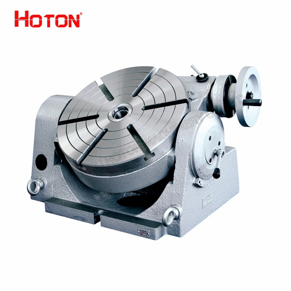
A rotary table is a precision work positioning device used in metalworking. It enables the operator to drill or cut work at exact intervals around a fixed (usually horizontal or vertical) axis. Some rotary tables allow the use of index plates for indexing operations, and some can also be fitted with dividing plates that enable regular work positioning at divisions for which indexing plates are not available. A rotary fixture used in this fashion is more appropriately called a dividing head (indexing head).
The table shown is a manually operated type. Powered tables under the control of CNC machines are now available, and provide a fourth axis to CNC milling machines. Rotary tables are made with a solid base, which has provision for clamping onto another table or fixture. The actual table is a precision-machined disc to which the work piece is clamped (T slots are generally provided for this purpose). This disc can rotate freely, for indexing, or under the control of a worm (handwheel), with the worm wheel portion being made part of the actual table. High precision tables are driven by backlash compensating duplex worms.
The ratio between worm and table is generally 40:1, 72:1 or 90:1 but may be any ratio that can be easily divided exactly into 360°. This is for ease of use when indexing plates are available. A graduated dial and, often, a vernier scale enable the operator to position the table, and thus the work affixed to it with great accuracy.
Rotary tables are most commonly mounted "flat", with the table rotating around a vertical axis, in the same plane as the cutter of a vertical milling machine. An alternate setup is to mount the rotary table on its end (or mount it "flat" on a 90° angle plate), so that it rotates about a horizontal axis. In this configuration a tailstock can also be used, thus holding the workpiece "between centers."
With the table mounted on a secondary table, the workpiece is accurately centered on the rotary table"s axis, which in turn is centered on the cutting tool"s axis. All three axes are thus coaxial. From this point, the secondary table can be offset in either the X or Y direction to set the cutter the desired distance from the workpiece"s center. This allows concentric machining operations on the workpiece. Placing the workpiece eccentrically a set distance from the center permits more complex curves to be cut. As with other setups on a vertical mill, the milling operation can be either drilling a series of concentric, and possibly equidistant holes, or face or end milling either circular or semicircular shapes and contours.
with the addition of a compound table on top of the rotary table, the user can move the center of rotation to anywhere on the part being cut. This enables an arc to be cut at any place on the part.
Additionally, if converted to stepper motor operation, with a CNC milling machine and a tailstock, a rotary table allows many parts to be made on a mill that otherwise would require a lathe.
Rotary tables have many applications, including being used in the manufacture and inspection process of important elements in aerospace, automation and scientific industries. The use of rotary tables stretches as far as the film and animation industry, being used to obtain accuracy and precision in filming and photography.

Our product range includes single and multiple axes, tilt/rotating tables, and indexing and high-speed spindles. Additionally, we offer customized solution tables for customer requests or OEM projects.
Even for EDM machines that have been in use for decades, we will work with you to determine the ideal rotary indexing table and/or rotating/indexing spindle solution.
Our state-of-the-art rotary indexing tables and customizable reference and clamping systems provide endless application possibilities and highly efficient solutions.

I am in the process of outfitting my new(old) Ex-Cell-O mill with some tooling. I have a line on a Phase II 222-410 10 inch tilting rotary table for what I believe is a good price. I believe that it fits in well with some of the work I am planning on doing, but I really don"t have a good feel for how it would work out in practice as opposed to in theory. The work I am planning on setting up for is checkering pistol front straps, specifically 1911 style. There are other patterns I plan to work with, but they all involve the same basic setups on the table. The cuts are made in vertical, as well as horizontal axis, around a radius. I included an example of the work I am describing. I have the basic idea for indexing the radius (which varies somewhat by manufacturer) as well as a fixture to hold the frames without marring the surface. My specific question is related to the accuracy/repeatability of the tilt. I would prefer to just turn the dial to 90 degrees without having to re-setup in the new axis. Are these units(assuming in good shape) able to consistently go between horizontal and vertical, once set up correctly. If so, It would probably save a great deal of time and eliminate at least some of the potential for human error? Also, Is it rigid enough to perform that type of work without inducing a lot of chatter or deflection. The work will all be light cuts.


 8613371530291