
servo driven rotary table free sample
Our direct drive rotary tables provide high torque and are easy to integrate. They contain high-energy magnets in a simplified mechanical design and drive loads directly without the need for a transmission mechanism or gearbox. It allows customers to build them right into a drive system for flexible placement and integration with cooling pipes and cables, for example.
We supply a wide range of frameless motors, and our adjustable motors include an optical encoder, scale, bearing and housing. Given our selection, it can be challenging to choose the best direct drive motor for your project. Our engineers prefer to help you find the right rotary table for your requirements.
Our most popular rotary motor, the AXD series is characterized by a slim, compact "pancake" design with high peak and continuous torque despite the motor"s quite small form factor.Direct drive and brushless motor
The ACD series is a set of ironless rotary tables. This motor is cogging-free and features high-resolution optical encoder feedback and low speed variability. This permanent magnet motor is equally suited for either low or high speed applications.Zero cogging coreless motor
Smaller versions can be used to power joints in robots for automation, powering pick-and-place applications, material handling, packaging and handling as well as servomechanism applications
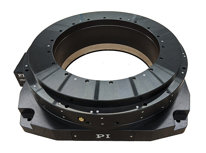
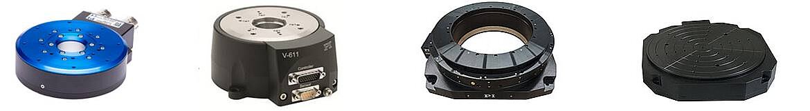
M-035 series high precision rotary tables rotation stages feature high resolution, excellent repeatability and minimum wobble. These high performance rotational positioning stages are equipped with double ball bearings for minimum backlash and high load capacity. Both the rotation stage platform and the scale ring (graduated in 2-degree increments) can be independently coarse positioned over 360 degrees and then be locked by screws.
The basic rotary table version, M-035.D0, is equipped with a DC servo motor drive providing a positioning range of ± 6.3 degrees. A set of limit switches eliminates the possibility of overtravel. For the highest precision and highest performance, high speed air bearing rotary tables are recommended.
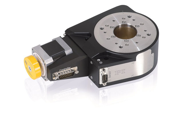
M-036 high performance series of closed-loop servo motor driven precision rotation tables provide the highest resolution, excellent repeatability and minimum wobble. The stages are equipped with double rotational ball bearings for minimum backlash and high load capacity. Both the rotation platform and the scale ring (graduated in 2-degree increments) can be independently coarse positioned over 360 degrees and then be locked by screws.
The basic version, M-036.D0, is equipped with a DC servo motor drive providing a rotational range of ±10.5 degrees. A set of limit switches eliminates the possibility of overtravel.
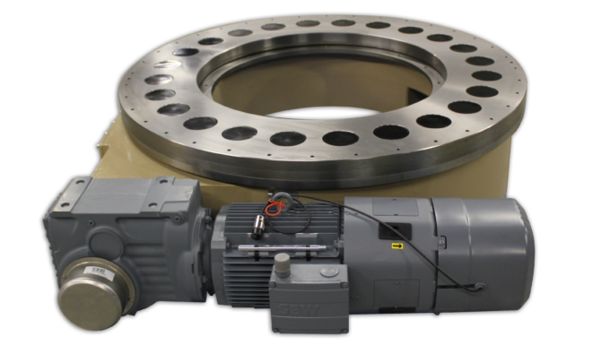
To achieve rotary motion, Cross Company pairs a rotary table with a servo motor, drive and control to create a complete rotary actuation system. This allows greater flexibility for your rotary positioner because you’re not tied to just one or two positions. Some examples of rotary actuation that Cross Company has worked on recently include:Robotic cells which require precise rotary indexing for manufacturing stations
Cross Company’s Automation Group works with several different manufacturers of motors, drives and rotary tables. We work with you to understand your application and then we size and specify the best combination for your particular need. We have literally decades of experience working with rotary actuators, so we can specify a robust solution optimized for the application.
Cross is proud to represent the following manufacturers of rotary positioners:Parker:Worm gear-driven precision rotaries, manual stages and direct drive rotary servo motors which are suitable for light to medium industrial precision positioning
In virtually every industry, a right-sized rotary solution increases the throughput and efficiency of your process. By working with Cross Company, we can help reduce the risk of incorrectly sized and specified equipment, delivering a complete solution perfectly tailored to your application. Contact the experts at Cross to discuss your rotary positioning needs.
The rotational inertia influences the inertia mismatch between the payload and motor, which in turn affects the servo system’s ability to control motion. While keeping the inertia mismatch below a 10:1 ratio is a good rule of thumb for applications using plug-and-play motors and drives, modern control systems can remain stable at far higher mismatches as long as you have no disturbances and are able to adjust the PID tuning. An SBR can easily be tuned for stable indexing at up to 200:1 and beyond.
Sample payloads are shown below with dotted lines representing one-inch thick aluminum plates of various outer diameters. This information can serve as a quick guide to controllable inertia ratios for different SBR and motor combinations. Other cases can be quickly assessed by mentally moving a dashed line downwards in proportion to your payload thickness. For example, if your table has a 12-inch diameter and 0.5-inch thickness, shift the 12-inch dashed line down by half to end the mismatch for a given house motor. Or, consider your actual payload inertia if known.

GOIZPER INDEXERS offers solutions to suit your applications. Servo rotary tables (or rotary indexing tables), flexible tables for welding cells, hemming, assembly and control. Ourrotary tables for automation systems can be used as rotating or positioning shafts or for a wide range of assembly applications. With a very high output rate and the shortest possible cycle times in addition to the highest standards of accuracy, they can increase the efficiency of your production processes for any application.
Our ZPGI range of servo rotary indexing tablewith heavy load positioning are ideal for dynamic, precise positioning of parts and large heavy equipment. Several versions of our cam operated servo driven rotary indexing table are available.

The DGII Series is a line of of products that combine a high rigidity hollow rotary table with an AlphaStep closed loop stepper motor and driver package. It retains the ease of use of a stepper motor, while also allowing for highly accurate positioning of large inertia loads.
If an overload is applied continuously, an alarm signal is output. When the positioning is complete, and END signal is output. This ensures the same level of reliability as a servo motor.
I am wondering how it would work to mount a stepper motor or servo motor on the rotary table. What all would I need in order to make a laptop computer operate the rotary table?Sherline makes a very small rotary table that is just what I am looking for but it is tiny. I need something bigger and stronger. The sherline looks like you can program a certain number of divisions and then every time you hit the button it moves to the next location.
Step 1: measure the amount of force it takes to turn the wheel, so you know what size stepper you need. Put some load on the table, like a heavy vise and pull the edge of table with 50+lbs of force (1/4 horsepower, scale up as needed) to simulate machining forces (although in your immediate app, you probably won"t be machining and moving at the same time). Give yourself a safety factor. A double ended shaft is recommended, so you can mount a handwheel on back end for manual operation. For a small table like the sherline, most NEMA-23 motors should work. For a larger one, you may need higher torque NEMA-23, NEMA-34, or geared steppers.
Step 2: physically mount motor to rotary table. On some tables, the shaft is supported on one end by a piece that bolts on. This provides convenient mounting. You may be able to machine a plate that has the original mounting holes, a bore for the bearing, and 4 holes for standoffs that match the stepper motor mounting holes. You will need a flex coupling. Bear in mind that the position of the shaft determines how well the gears mate and how much backlash there is. You may want slots for the mounting holes so you can slide the plate.
Step 5: PC interface. If your laptop has a parallel port, all you need to do is connect ground, step, and direction. The latter two can be connected to D0 and D1 on the parallel port. You will configure the software to tell it what pins you used. Parallel ports are going the way of dodo birds. USB->Parallel adapters are not suitable. USB is a bit trickier, though there are some stepper controllers available: here is one: http://www.usbcnc.com/index_products.html. I have seen a cheaper one designed by someone here or on CNCzone that looked halfway decent but can"t find it at the moment. About EU$69, USB, PIC based, 3 axis, no source code, windoze software included. Looked adequate for what you are doing but not for my purposes:

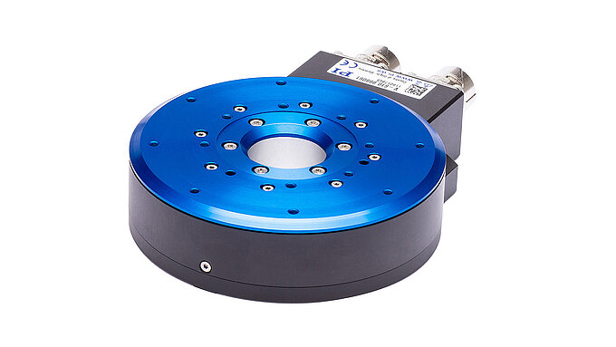
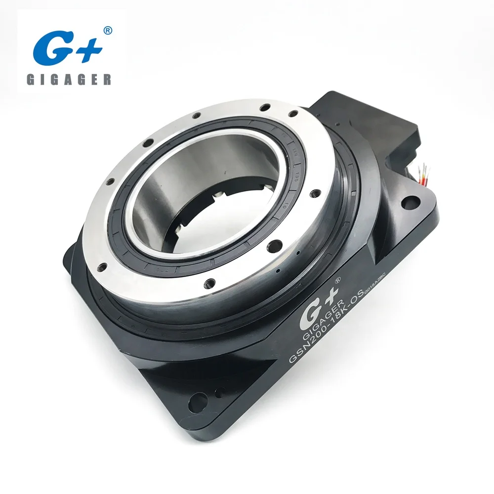
This compact closed-loop direct drive rotary table uses a 3-phase motor for maintenance free, frictionless power transmission. It comes in two variations, standard and with holding brake.
Application video of the silent ultrasonic piezo motor rotary stage in a Leica Theodolite and Principle Design of the PILine drive used in the M-660 PILine� rotary stage
This miniaturized closed-loop rotary positioner is driven by an ultrasonic direct-drive motor and provides high rotational velocity up to 3 revolutions / second. An optical encoder is integrated for direct position measurement and feedback with 35 �rad resolution.
Q-motion series miniature rotation stages are driven by inertia-type piezo motors. These miniaturized positoining tables are direct-driven, backlash free and provide micro-radian resolution. The self-locking design requires no holding current and provides excellent long-term stability. Three different diameters are available: 14 mm, 22 mm and 32 mm.
P-5x8 series, Z/tip/tilt nanopositioners are open-frame, high-resolution, piezo-driven stages providing Z motion to 240 �m and rotation around X and Y to 2.4 mrad with resolutions of up to 0.5 nm and 50 nrad. The 66 x 66 mm clear aperture is ideal for transmitted-light applications.
Goniometric cradles are used to rotate samples and objects to a precise angular position. The units here are equipped with precision servo and stepper motors and high-resolution encoders for angular position feedback.
Rotary indexing table use is widespread in automated assembly machinery and selecting the proper mechanism is essential for both maximizing performance and minimizing the cost of this critical component. This how-to-guide will explore two common devices that can be used for rotary indexing and give advice for proper selection. These two popular devices are cam indexing drives and servo rotary tables.
Cam indexers are a ubiquitous mechanism that have been used for rotary tables for many decades. They are a great fit for applications that will always index the same angle and that require high-precision positioning at a very reasonable cost. A cam indexer uses a mechanical cam to provide the motion control to position the load. A mathematical motion curve is machined onto the cam that provides extremely smooth and repeatable motion.
A cam indexer has two main modes of operation. One mode is referred to as “Cycle-on-Demand”. This indicates that the camshaft will be cycled one revolution at a time to advance the output one position at a time. This is typically achieved by using an inexpensive camshaft sensor package to detect camshaft position and a VFD to stop and start the motor. The camshaft dwell period offers a wide window for the camshaft to stop without affecting the position of the output. To cycle the indexer, a PLC gives a command to the VFD to accelerate the drive motor to a preset speed, the cam rotates one revolution indexing the output, a sensor sends an in-position signal to the PLC, and the PLC signals the VFD to stop the camshaft during the cam dwell position. The table will be in the dwell position for however long is necessary to complete the work at each station. The dwell time can range from a fraction of a second to several minutes or hours depending on the application. This combination allows very accurate positioning with an inexpensive drive system.
A fully programmable servo rotary table is another common option. There are two specific cases where a servo rotary table is advantageous. The first is when a flexible motion pattern is required. An example is two different products being run on one machine that each require different indexing patterns. The other situation that suits a servo indexer is when extremely fast positioning is required followed by a long dwell period. A cycle-on-demand cam indexer is limited by the need to accelerate the camshaft up to speed during the dwell period before output motion is started. There are practical limitations to how fast the camshaft can be accelerated so there will be a delay before motion is started. With a servo rotary table, the output rotates as soon as the servomotor starts moving. A practical example would be a load being indexed 90 degrees in 0.25 seconds. This is not difficult for a continuous cam indexer or a zero-backlash servo indexer, but a cycle-on-demand cam indexer may struggle with that motion. For quick servo indexing applications, a preloaded gear reducer with zero-backlash is critical to achieving smooth indexing motions with minimal settling time. A zero-backlash RollerDrive mechanism would be an optimal choice to achieve accurate positioning with great dynamic response.
For either style of indexer, application information including moment of inertia, indexing angle, indexing time, and dwell time is required. A reputable manufacture should then be able to properly size the rotary table for the application.


 8613371530291