
cmm rotary table free sample

Coordinate measuring machines (CMMs) play a vital part in precision engineering and quality control in the aerospace industry. Indeed, the global dimensional metrology market in the aerospace industry generated $482.9 million in 2012, with the CMM segment expected to grow at a compound annual growth rate of 4.0% by 2017 according to some commentators.
It’s no secret that all major aerospace manufacturers use CMM machines, sometimes as intensely as 16 hours a day, to measure the physical geometrical characteristics of aerospace components. But what is less well known is that using a rotary table on a CMM machine will help it work smarter.
So what’s the benefit of using a rotary table on a CMM machine? According to Jim Palmer from RPI, a leader in rotational innovation, the answer is simple:
“When it comes to measuring symmetrical or prismatic components, it’s all about simplifying your measuring procedures, increasing your CMM’s application range and effective measuring volume which in turn will increase the flexibility, productivity and efficiency of your CMM.”
Matt Brady at Nikon Metrology UK agrees that rotary tables bring significant benefits to CMM machines. Nikon, whose range of coordinate measuring machines represent the ultimate in CMM technology, is a longstanding customer of RPI and has been fitting RPI’s rotary tables to its CMM machines for decades.
Commenting on RPI’s rotary tables, Brady said: “We supply CMMs to aerospace customers all over the world and many of our customers say that using RPI rotary tables significantly reduce inspection time. Indeed, one such customer reduced inspection times by four hours, a saving of 40% by using a CMM machine fitted with an RPI rotary table.
Rotary tables are therefore an ideal addition to CMM machines - particularly for measuring complex parts such as rotor discs. For example, using a rotary table on a CMM machine will improve process efficiency and productivity by reducing set up and process times. A rotary table will also greatly increase a CMM machine’s available measuring volume thereby providing greater flexibility in what can be measured. And last, but by no means least; a rotary table will also significantly improve overall measurement accuracy of a CMM machine thereby reducing uncertainty.
Bath-based RPI has a very large share of the market in those CMMs which use rotary tables and can boast more than 500 successful installations worldwide. RPI grew out of acquisitions from Airmatic, Optical Measuring Tools, and Eimeldingen. Since the 1950s it has been one of the world’s largest designers and manufacturers of precision rotary tables and a leading supplier of rotary tables to the aerospace, automotive, power generation, machine tool, scientific and general engineering industries.
RPI’s rotary tables are widely used by all leading CMM manufacturers, including Nikon, Mitutoyo, Hexagon and Renishaw, and have been specifically designed as a fourth axis for all types of precision CMM machines. They are accurate to ±0.5 arcs seconds, which is the equivalent to hitting a golf ball at a hole more than 22km away and scoring a hole in one every time.
“Let’s say you wanted to measure a rotor disc,” continues Palmer. “Simply using a standard CMM over one fitted with a rotary table would require a machine with a much larger overall measuring volume. This is because the volume of the CMM machine is directly related to the diameter of the disc as voluminous styli systems are usually required to measure a workpiece from all sides which means a large proportion of its measuring range is required just to ensure collision-free movement of the stylus around the part.”
However, the introduction of the rotary table removes this requirement as the rotor can be presented directly to the stylus removing the requirement to access all sides. This in turn simplifies the stylus system allowing the measurement of larger workpieces in relation to the available measuring range, saving aerospace manufacturers both time and money.
RPI’s rotary tables come in a wide size range; from 400mm to 1,200mm and can be fully integrated to the host machine controller. One of the unique selling points of RPI’s CMM rotary tables is their multiple bearing configurations: mechanical or air combination bearing.
The mechanical bearing rotary table combines a high precision, high load capacity, roller thrust bearing resulting in excellent rotational characteristics with a pre-loaded; double row journal bearing to eliminate radial movement in the table’s axis; ideal for heavy off centred loads.
Whereas RPI’s combination bearing rotary table combines the same pre-loaded; double row journal bearing as the mechanical bearing table with a high load capacity thin film air thrust bearing. The thrust bearing uses a thin layer of air trapped between the underside of the table top and the top of the base assembly. The thrust bearing is supplied using a series of orifice plugs machined into the table base; ideal for heavy centred loads.
Because they are so well made, RPI’s rotary tables last for decades only needing servicing to be as good as the day they rolled off the production line. As you’d expect, RPI provides a comprehensive rotary table, repair, overhaul and angular calibration service.
Clearly, you don’t have to go round in circles to see the significant benefits a rotary table can bring to CMM machines used in the aerospace industry. So, if your CMM machine isn’t benefitting from a rotary table, isn’t it time you invested in some rotational innovation?
Accuracy and repeatability is the lifeblood of all CMMs. If they aren’t accurate, there’s no point in having them. However, the degree of accuracy required is dependent on the particular application. For manufacturing gas turbines and aircraft engines, a very high degree of accuracy is often required.
Well, that level of accuracy can be achieved with high precision rotary tables. These can deliver precision geometry with axial performance well below 0.0005mm and positional accuracies to ±0.5 arc-seconds (±0.00014°).
Using a rotary table on a CMM will improve process efficiency and productivity by reducing setup and process times. A rotary table will also greatly increase a CMM’s available measuring volume thereby providing greater flexibility in what can be measured. And last but by no means least, a rotary table will also significantly improve overall measurement accuracy of a CMM, thereby reducing uncertainty.
Rotary tables enable very precise measurement of many geometrical characteristics, including angle, roundness, concentricity, parallelism, flatness and runout. They are used with: probes such as plunger, transducer and capacitance; optical such as autocollimator and laser interferometer; and electrical: oscilloscope and voltmeter.
Rotary tables enable accurate measurement of symmetrical/prismatic components such as rotor discs. In the measurement of a rotor disc, a CMM without a rotary table would require a machine with a large measuring volume. However, deploying a rotary table will reduce this volume significantly. This is because the volume of the CMM is directly related to the diameter of the disc as voluminous styli systems are usually required to measure a workpiece from all sides. This means a large proportion of its measuring range is required just to ensure collision free movement of the stylus around the part.
However, the introduction of the rotary table removes this requirement as the rotor can be presented directly to the stylus removing the requirement to access all sides. This in turn simplifies the stylus system allowing the measurement of larger workpieces in relation to the available measuring range, saving aerospace manufacturers both time and money.
As well as significantly improving overall measurement accuracy and reducing uncertainty in CMMs, rotary tables also greatly increase a CMM’s available measuring volume thereby providing greater flexibility in what can be measured.
Some tables have been specifically designed as a fourth axis for any high precision CMM to simplify measurement procedures, increase application range and measuring volume of symmetrical or prismatic components, including scanning applications. This is particularly important for large turbine disks for gas turbines or for airplanes. However, they are also starting to gain traction for smaller, lower measurement volume applications typical in the automotive industry.
Air bearing spin tables are becoming more popular and rely on air lubricated hydrostatic bearings which provide very high radial and axial stiffness. This type of bearing offers significant advantages over conventional rolling element bearings permitting operation with minimal drag, vibration and mechanical noise.
These tables can be combined with direct drive motors and high accuracy angular encoders. The encoder couples directly to the motor control system, which has its own high-resolution interpolator ensuring precise positioning and repeatability.
It is possible to fit a table with a high accuracy Hirth Coupling, which provides location and angular positioning of the tabletop. This delivers fast, accurate indexing between pre-set positions.
Rotary tables are so accurate that they can be forgotten, when using a CMM. And that’s no bad thing for manufacturers who need precision time and time again.
The CMM Checking Gauge (CCG) gives confidence in the accuracy of your CMM, by enabling independent verification of accuracy using regular intermediate checks…
During measurement, and particularly when scanning, contaminants such as remnants of coolant, dust, oil and oxides build-up on the stylus of your CMM.
Typical applications that benefit from an additional rotary axis include the measurement of component parts characterised by symmetrical, recurring or internal geometry - including rotating shafts and discs, casings and housings, turbines and compressor parts, and bearing components.
Low profile surface mounted rotary table with integrated air flotation base – allows the table to glide effortlessly over the surface when positioning the table on the CMM:
Fixturing components correctly during inspection is essential for measurement accuracy and reproducibility. LK Metrology fixture kits are designed to support components securely and with minimum force, while providing a clear access path for the probe. A range of clamps, holders and adjustable supports provide great flexibility for fixturing a host of different shape parts and types of material.
The SOLO handbox has been ergonomically designed with time saving features that put the operator in full control. The intuitive keypad provides control over the software, probe and CMM without returning to the PC. For accuracy in manual mode the 3D joystick features touch‐sense technology for smooth motion and precise positioning.
Soft‐touch buttons offer dual functions and frequently used settings, while LEDs give a visual indication of status and warnings all at your fingertips and in the palm of a hand. Available as standard with new NMC controllers and LK CMMs, or as a retrofit for non LK CMMs with cable lengths ranging from 5 to 25 meters.

All three axis movements are controlled from the one joystick. Moving the joystick left, right, backwards and forwards controls the CMM X and Y movements. The Z-axis is controlled by twisting the joystick clockwise and anti-clockwise (configurable)*.
If a trigger event occurs during joystick operation, the CMM will stop and back away from the surface along the vector that it was travelling. After the back off operation, it is necessary for the joystick to return to its null position for a set period of time before the joystick will permit movement of the CMM. The default value is 0.05 seconds*. The back-off speeds and distances are defined by the UCC configuration settings*.
The joystick enable button(s) are intended to be used to prevent the accidental movement of the machine. Two actions are required to initiate CMM motion: press joystick enable button and operate the joystick.
These permit the locking of one or more axes of the CMM, ignoring any joystick deflections for that axis. On each of the axis lock buttons there is an LED indicator that will light red when the respective axis is locked. On the MCU display there will also be a padlock symbol next to the respective axis (see below). These buttons toggle the lock on / off.
When the MCU is in head mode, the axis locks are applied to the relevant head axes. When the joystick is in head mode and a REVO / REVO-2 / PH20 head is fitted, the left / right axis lock button is used to initialise and cancel ‘SNAP ON". ‘SNAP ON" is the ability to move the head to the nearest multiple of a defined head angle. In UCCassist-2 the variable can be set to define the resolution of manual head moves (e.g. 5°). These axis locks will only be active during manual (MCU) controlled CMM movements. When the CMM is under DCC (direct computer control) operation, all axis locks will be released and re-latched when returning to manual operation.
This button is designed to allow the user to record or cancel chosen machine positions. When a program is being generated by the teach and learn method, the take point button is used to permit the CMM to record a waypoint and use it in the program. Use of the cancel point button will indicate to the application software that the point just taken (either a touch point or a position generated by the take point button) should be removed from the program. The cancelling process can be repeated many times and the front-end program will use it to delete multiple stored points.
In this axis system, the joystick directly controls the machine axes, i.e. a forward deflection of the joystick produces a pure Y+ movement of the CMM. This is the default machine setting when the machine is initialised.
The axis system in which the MCU is moving the CMM (machine, part co-ordinate or stylus) is indicated on the LCD by an M, P or S and by a tri-colour LED mounted below the axis select button. Pressing the axis select button will enable the user to scroll through the three axis systems.
The joystick orientation button changes the mapping of joystick deflection direction to CMM axis. This allows the user to move freely around any side of the CMM and transpose the joystick orientation such that the machine"s X-axis and Y-axis correspond to joystick direction of deflection. If any axis lock is asserted and the joystick orientation is changed then the relative axis lock will also be transposed.
NOTE:When switching the system to CMM auto mode, the joystick orientation feature will drop out and then be reasserted when the system is placed into CMM manual mode.
This button switches between CMM and rotary table operation.If there is no rotary table this button has no effect. The rotary table is set up during commissioning in UCCassist-2.
The engage button gives the CMM user the ability to engage or disengage the servos whilst the CMM is in manual mode. This button is configured as a toggle switch and has an associated LED to indicate the servo status. The LED identifies the various operational states as listed below. A symbol at the top of the LCD screen (shown below) also indicates whether the servos are engaged.
The STOP button gives the operator the ability to rapidly stop the CMM, REVO head and PH20 without disengaging. When the CMM has stopped, the system stays in hold state with both the CMM and head engaged.
This is the yellow or grey STOP button mounted on the MCU W-2 joystick, or the grey button on the MCU5-2. When this button is pressed, all CMM and motorised head motion is halted.
A red or grey emergency STOP switch is mounted on the MCUlite-2, MCU5-2 and on the MCU W-2 cradle which is hard wired to the UCC controller. It complies with EN13850 and when connected to a UCC / SPA the system can comply as either a category 2 or category B E-STOP system as defined in EN954-1:1996 (ISO13849-1:1999). When this switch is operated power to all the CMM axes is removed.
Speed override controls the machine speed when the CMM is running a program under DCC mode. It will also control the speed of the REVO head or PH20 if fitted. The LCD screen displays a percentage value of the programmed move speed when in DCC operation as shown below. If the speed override is set to less than 10%, the speed percentage shown on the LCD display will flash.
If the joystick is taken out of range while the CMM is moving in automatic mode the loss of the radio link will not stop the CMM, but if the speed control is changed while the joystick is out of range the following actions are required when the joystick is reconnected.If the new demanded speed is lower than the value set before the link was lost then the CMM will immediately slow down to the new speed when the joystick link is reconnected.
If the new demanded speed is higher than the value set before the link was lost then, when the joystick link is reconnected, the CMM will keep on moving at the old speed but the display of % speed will be reversed (white on black as shown below). The speed will be frozen until the speed control is turned down through the old speed value. The speed control will then again be functional.
The probe disable button gives the CMM user the ability to move the CMM while the probe is triggered or disconnected by disabling the probe trigger signal.
WARNING:When operating in this mode the probe is disabled and therefore probe contact with a surface will NOT stop the CMM. No measured data will be returned to the CMM host computer.
The probe disable function will only work while in manual mode and cannot be applied while in automatic / DCC mode. To disable the probe, press and hold the joystick enable button and then press the probe disable button. The CMM can now be moved irrespective of the probe trigger status. Releasing the joystick enable button cancels the probe disable function. In all modes the application of probe disable is confirmed by the red probe disabled LED being illuminated.
![]()
ZEISS FutureFit allows you to retrofit many additional functions. This keeps your processes cost-effective and reliable. With ZEISS FutureFit, the CMM control (C99 types) is brought up to the current series status, thus enabling simplified and efficient service. It also serves as a basis for software maintenance contracts and extended software functions and enables you to use current and future software versions.

The rotary table movements are animated very easily. Just insert a machine definition that contains a rotary table as was stated in post #11.2. Here is a simple machine definition that is nothing but a big rotary table oriented in the XY plane. Copy this into UserMachine.dat, insert the Load/Machine command into your program, and you should be all set. Adjust the machine travel limits, etc. to suite your machine.
Do you know how dimensions and tolerances for complex parts are measured? Often, a coordinate measurement machine or CMM is used. In this article, we will look at different types of CMM’s and discuss how they work and when they are used.
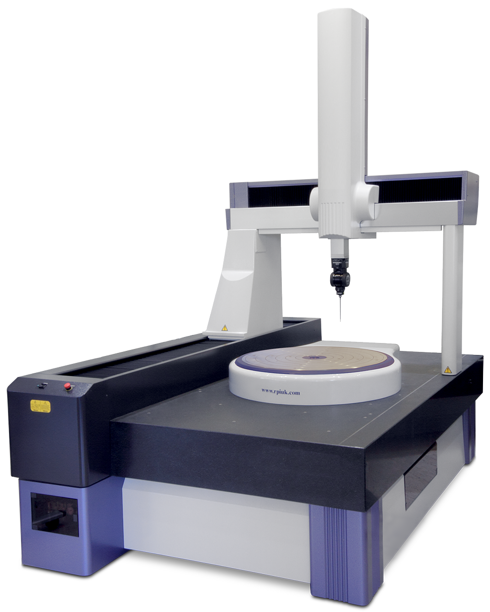
A coordinate measuring machine is an instrument that is used to collect measurements of three-dimensional objects. A CMM consists of a structure that moves in three dimensions, a probe attached to the structure, and a computer control and/or recording system. All coordinate measuring machines operate in the same way: the probe touches points on the object to be measured, and the position of the structure is recorded. Each measurement point is described by X, Y, and Z coordinates. All the measured points for a single object are combined into a 3D CAD file known as a point cloud. The point cloud can be compared to a 3D design drawing to determine if the object has been manufactured to the correct dimensions.
CMM’s come in all shapes and sizes, depending on the objects to be measured. The smallest CMM’s can be portable, but the largest CMM’s require a custom concrete foundation. Articulating arm, horizontal arm, bridge, and gantry are some of the common CMM configurations. Below, we will discuss general characteristics of each configuration.
These compact, versatile CMM’s consist of a vertical post with multiple articulating segments and up to 8 axes of movement. A probe is mounted to an articulating joint at the end of the arm, and they often have a laser scanning apparatus allowing for the use of either or both at the same time. The articulating joints allow the probe or scanner to be angled to collect measurements in hard to reach areas. These machines are manipulated by hand to place the probe or scanner at the point to be measured. The photos below show articulating arm type CMMs in use.
These CMM’s are highly portable and do not require climate-controlled rooms for operation. They can be used to collect field measurements from installed parts. Advertised accuracy is as high as 0.0002”, but the setup’s environmental conditions can limit it. Additionally, the measuring range of these machines is limited only by the arm’s reach, so they can be used to measure a wide variety of parts, making them well-suited for many commercial machine shop applications. However, articulating arm CMM’s cannot perform an automatic measurement, and they are not typically used for measurement in high-volume manufacturing processes.
The basic structure of this type of CMM consists of a base with one or more articulating arms or beams. A probe is mounted on a rotating joint at the end of the arm. The arms can be extended or retracted from the base in any direction and will also pivot about the base, allowing for measurements in three axes. However, for some configurations, the probe is capable of traversing perpendicular to the base on a horizontal arm, providing a third measurement axis. The photo below shows a portable, rotating, horizontal arm type CMM manufactured by zCAT.
Horizontal arm CMM’s can be huge, and one common application for large machines is automobile body measurement. The photo below shows a pair of horizontal arm CMM’s manufactured by Mitutoyo.
This type of CMM is often fully computer-controlled, allowing them to measure, record, and evaluate data without operator intervention. A joystick for manual operation can control some machines. Accuracy is typically better than an articulating arm CMM, but it suffers somewhat from an inherent lack of rigidity in the cantilevered design.
Bridge machines are the most common type of CMM. These machines are typically benchtop or floor-mounted and comprised of a granite measurement table, a “bridge” structure that moves horizontally above the table, a vertical beam that moves along the bridge structure as well as vertically, and a probe mounted to the bottom of the vertical beam via a rotary joint. The bridge traverse movement function is typically driven from one side only and equipped with air bearings to minimize friction.
Bridge CMM’s can be manually controlled or fully automated. The rigid bridge structure makes this the most accurate type of CCM, and temperature compensation is often available.
The largest CMM’s are gantry type. These machines are mounted on custom foundations and installed in bespoke climate-controlled buildings. The layout is similar to bridge machines. Accessibility and the ability to measure very large parts are the primary advantages of a gantry CMM.
CMM’s use linear scales (sometimes called linear encoders) to measure translation movements in the X, Y, and Z axes. These scales can operate on a variety of principles, but generally consist of a strip that encodes position information and a sensor that reads the strip. Common types of encoding are optical, magnetic, capacitive, inductive, and eddy current.
Rotary encoders operate on the same principles as linear encoders, and they are used to monitor the angles of articulating joints. From the encoder angle and known member lengths, trigonometry is used to calculate the probe position. Coordinates are adjusted to provide the proper X, Y, Z coordinates for the measurement.
CMM probes are often touch-triggered, collecting a measurement point every time they touch a surface. A typical probe tip consists of a spherical ruby mounted to the end of a thin stylus. When the probe touches a surface, it transfers pressure through the stylus to a sensor within the probe body, triggering a measurement.
In some cases, contact probes can be replaced with optical scanning probes. These scanning probes use reflections of light to triangulate measurement points on the object’s surface. Recently, advances in technology have allowed optical scanners to increase in accuracy and range. As a result, stand-alone optical scanners are replacing CMM’s for some applications.
CMM’s are used for various purposes, including quality inspection, field inspection, creation of drawings for existing equipment, and measurement of worn parts for refurbishment.
CMM’s can quickly and accurately obtain measurements for many geometrical features that would otherwise be very difficult to measure. For example, a CMM could easily check the profile of a surface to determine if a turbine blade is manufactured to the proper curvature. Other properties commonly measured with a CMM include flatness, straightness, circularity, cylindricity, the profile of a line (of a complex curve), concentricity, symmetry, and axial location/orientation.
Operation and programming of coordinate measurement machines are typically conducted by someone who has received specific training for that purpose. Training materials and courses relating to CMM operation are commonly available from the equipment manufacturer. Since CMM operators are often checking the dimensions of a part against a drawing or design, the ability to read technical drawings and knowledge of geometric dimensioning and tolerancing, or GD&T, is essential for these personnel.

RPI UK, the world’s leading specialist developer and manufacturer of precision positioning devices for high accuracy rotary and angular inspection systems, has welcomed Mitutoyo as a new customer following the Japanese manufacturers decision to invest in 10 rotary tables.
Mitutoyo, one of the world’s leading manufacturers of precision measuring equipment, has integrated three QuadMatic and seven QuadSlimLine rotary tables into its high precision co-ordinate measurement machines (CMM) at its Japanese and UK operations.
RPI engineers travelled to Japan to support Mitutoyo with training and maintenance and were also on hand to help integrate a two-axis rotary table at Mitutoyo in Halifax.
RPI’s rotary tables are an ideal addition to high precision CMMs. Specifically designed as a fourth axis, they are accurate to +/- 0.5 arcs seconds. This is equivalent to hitting a golf ball at a hole more than 22km away and scoring a hole in one every time!
Jim Palmer, RPI’s sales manager, said: “It’s great news that Mitutoyo has chosen to invest in 10 of our Quadrant range rotary tables. As well as significantly improving overall measurement accuracy and reducing uncertainty, our rotary tables also greatly increase measuring volume, thereby improving the flexibility, productivity and efficiency of our customers’ CMM.”
The addition of Mitutoyo to RPI’s customer base means the Bath-based manufacturer now supplies all the major CMM manufacturers which use rotary tables, from Hexagon to Renishaw and LK to Wenzel.
The QuadSlimLine and QuadMatic are part of RPI’s Quadrant range of CMM tables which also includes the QuadDualPurpose, QuadProfile and the QuadUniversal. They come in a wide size range; from Ø200mm to Ø1500mm and can be fully integrated to the host machine controller.
RPI grew out of acquisitions from Optical Measuring Tools, Airmatic, Horstmannn and Eimeldingen. It is now one of the world’s largest designers and manufacturers of solution driven, highly accurate inspection systems and services that measure circular geometry and angular positioning. Using its 75 years of rotary expertise, RPI supplies progressive engineering industries, including the aerospace, gas turbine and dimensional metrology sectors, with exceedingly dependable, low maintenance products with a service life measured in decades, not just years.
Mark Boucher Consulting, a CMM Quarterly company, offers the best training in the business whether you need onsite, over the web training or programming. Click on the image above to view our services.

Air Bearing Rotary Tables, Table Top and Work Load are Supported on Air Bearings whose Freedom from Friction Contributes to Extremely High Positional Accuracy
An Interlocking Switch is used when Motors are Incorporated to Prevent the Table Top from Moving when the Air Supply is Turned Off. When the Air Supply is Turned Off, the Table Top Sits Firmly on our Cast Base with an Extremely High Accuracy of Parallelism Between the Base and Table Top
Rotary tables specifically developed for use in Metrology applications. CMM tables, inspection tables, assembly tables. Range of sizes 100mm thru 5,000mm. Larger on request.
Air bearing rotary tables, when rotating, the table top and work load are supported on air bearings whose freedom from friction contributes to the extremely high positional accuracy. High precision needle roller bearing maintains radial accuracy.
Supplied with each table. On/off Switch controls the compressed air supply to the table. Interlocking ensures that the motor drive can only operate if the air supply is on. When air supply is off, table sits firmly on the base casting with extremely high accuracy of parallelism between the top surface and the underside of the base.


 8613371530291