
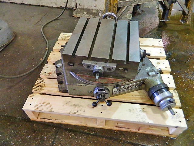
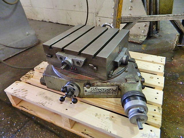
advance cross slide rotary table made in china

Up for sale is a used Advance Cross Slide Rotary Table in very good condition that has a 11" x 11" table top working surface , with T-Slots. It comes with 1 handle for the Rotary and 1 handle for the 4 sides that control X & Y axis depending on which way you mount it in your machine. It has 4" travel in the plus direction and 4" travel in the minus direction on each axis giving you 8" travel in the X & Y directions. It stands approximately 9 1/4" tall from the bottom of the base to the table top work surface. If you have any questions, please call us @ 262-895-3462 or email us. This is a great addition to mount on your Vertical Mill or Horizontal Boring Bar; CNC or Manual Type.

Lathe slides are designed to resist only turning forces which is usually directly down onto the slide. You are milling which puts loads on the slide it wouldn"t normally see. Make sure that the gibs on your slides are snugged up to reduce any lift or lash and if you don"t intend moving the slide during your milling, lock it up tight.
Another thing I would do it add some support to the rear of the table. If you can fix an angle or block to the base and clamp it down then you"ll find it a lot more rigind.
Finally your clamping of the part leaves a lot to be desired. You"re milling a long way from the clamp and if that flat bar is even slightly bowed it will hinge all over the place. You could put a second clamp on it ir if you don"t have the room for that without fouling the cutter try at least putting some low level stops in the dis-used slots to prevent hinging. Another thing you could do is put a piece of paper under the part near each edge of the table. That will improve clamping forces a lot.

The clearance problem with vertical mode goes beyond mill envelope. Imagine using a 12" rotary table in vertical mode to hold a shop made (or repaired) face mill or inserted mill. Or a gear blank, or anything relatively small. Just getting the quill past the table so that the cutter can get to the part can be a problem. Use of a tail-stock and mandrel can help in some cases, but there are parts that do not lend themselves to such things.
Of them all, the only one I think I could live without would be the 8" horizontal, but that would mean hoisting that 200 lbs Troyke onto the table more often.
The mill works better than I had expected. I think the last mill project I had was to duplicate the "jaw" of a movement post: the brass one had stripped out, so I replaced it with a steel one, salvaging the steel from a trash-can axle. As on any machine tool you have to expect some flexing, and so light cuts are helpful if you"re dealing with anything but aluminum. I don"t think I can use any but the smallest and simplest rotary table-thing (with or without chuck) given the space constraints.

The mill rotary table is one of the main accessories of milling machine. As a precision work positioning device, it is widely used for indexing drilling, milling, circumferential cutting, boring, etc. The rotary turn table for milling machine is made from HT200 casting with high quality. It has already passed the ISO9001 quality system certification. They are are very popular on the market for their superior performance, excellent design and reasonable cost.
Both vertical and horizontal with two functions. Circle cutting, indexing drilling, milling and more complicated work are possible when the vertical position of the table is used together with the tail part.
Abstract: Provided is a device for converting rotary motion into oscillatory axial motion, which device comprises: (a) a rotation element (1); (b) a base element (2); and (c) one or more bearings (3) for facilitating rotary motion of the rotation element relative to the base element; wherein the rotation element and/or the base element comprise one or more raised portions (4) and/or one or more lowered portions (5) over which portions the one or more bearings (3) pass in order to periodically increase and decrease axial distance between the rotation element (1) and the base element (2) as rotation occurs, thereby imparting an oscillatory axial motion to the rotation element (1) relative to the base element (2).
Abstract: Disclosed is a cooling and lubricating system (and method of use) for an RCD bearing/seal assembly comprising an internal conduit for directing fresh oil into the lower end of the bearing assembly where it can then progress upwardly through the bearing assembly and seals to provide cooling and lubrication to the internal bearings and rotary seals. The RCD system employs a small footprint oiler to deliver, via pressurized air, the oil to the RCD. Also disclosed is an RCD bearing assembly outfitted with the oil channel conduits for directing oil through the RCD bearing assembly to cool and lubricate the seals and bearings.
Abstract: The invention relates to a drilling tool for earth drilling with a drill rod element which can be connected to a rotary drive and can be driven in a rotating manner about a drilling axis, a frame-like housing and at least one removal tooth which is supported in a radially adjustable manner in the housing between a retracted position in the housing and an operating position, in which the at least one removal tooth projects radially from the housing. Furthermore, on the drill rod element in the housing a transmission mechanism is arranged, through which a stroke and/or rotational movement of the drill rod element can be translated into a radial movement for radial adjustment of the at least one removal tooth.
Abstract: A drilling table for a drilling rig has an accommodation sleeve that can be rotated via a rotational drive for accommodation of a Kelly rod provided with driving contours. Coupling elements are disposed on the inside wall of the accommodation sleeve for engagement into the driving contours of the Kelly rod for transfer of torque and bias forces. Broken-out areas are introduced into the accommodation sleeve, through which areas the coupling elements that can be inserted from the outside are passed, to project into the sleeve interior. A drilling rig has such a drilling table.
Abstract: A rotary table device is provided with means arranged for suspension of a pipe string. The rotary table comprises a rotary ring arranged rotatably about the central axis of the rotary table. The rotary ring is formed by two or more ring sections, each connected to a system comprising a bearing housing section rotatable relative to a base section, a bearing housing groove being formed in a base contact surface on the bearing housing section and a corresponding base groove being formed in an opposing bearing housing surface in the base section. The grooves form a curve-shaped track for a roller body and the groove has a curvature center coinciding with the central axis of the rotary table. The rolling diameter of the roller body exceeds the collective depth of said grooves, and a channel connecting the end portions of the bearing housing groove is formed in the bearing housing section.
Abstract: The present invention is directed to the configuration of an elongate inner member of a dual-member pipe. The elongate inner member of the dual-member pipe is disposed within an outer member and rotatable independent of the outer member. The inner member comprises a geometrically-shaped pin end and a box end having a geometrically-shaped opening. The geometrically-shaped opening of the box end has at least one internal angle greater than 180 degrees. The pin end of the inner member may be inserted into the box end of an adjacent similarly formed inner member to form an inner member pipe joint. The configuration of the pin end and the box end allows the pin end and the box end to be in connector free torque-transmitting engagement but also provides clearance for potential misalignment of the pin end and the box during make-up of an inner member drill string.
Abstract: A drilling machine includes a feed cable system which operatively couples a rotary head to a tower. The feed cable system includes first and second pull up cables and an equalizer bar, wherein the equalizer bar is coupled to the first and second pull up cables. The equalizer bar drives the rotary head to be held in a level position so that it is restricted from tilting. The drilling machine includes a slack take up device which couples the equalizer bar to the tower. The slack take up device is repeatably moveable between extended and retracted conditions.
Abstract: A force compensator for a top drive assembly includes a carrier block, a pair of top drive link assemblies, a mandrel, and a shock absorber assembly. The top drive link assemblies being positionable on either side of a power swivel and having a lower end connectable to the power swivel, an upper end connected to the carrier block, and being slidably positionable on a derrick of a drilling rig. The mandrel is slidably disposed through the carrier block and has an upper end connectable to a mover assembly of the drilling rig. The shock absorber assembly is interposed between the carrier block and a lower end of the mandrel in such a way that the shock absorber assembly is movable between an expanded condition and a compressed condition.
Abstract: Disclosed are hydrocarbon recovery drill string apparatus, subterranean hydrocarbon recovery drilling methods, and subterranean hydrocarbon recovery methods. In one embodiment, a hydrocarbon recovery drill string apparatus includes an elongated assembly within which a rotatable drill rod is received. The assembly comprises a longitudinal axis, a drill rod entrance end, and a drill rod exit end. The assembly comprises a tailcuttings diverter pipe proximate the drill rod exit end, with the tailcuttings diverter pipe defining an initial fluid flow path of the tailcuttings from the longitudinal axis which is acute from the longitudinal axis. Other apparatus and method aspects are contemplated.
Abstract: A device is for a drilling rig for forming of a bore hole in a subterranean structure. The drilling rig comprises a first, top driven drilling machine arranged vertically displaceable along a guide track, where a second drilling machine is arranged between the first drilling machine and the bore hole, vertically displaceable along a guide track and provided with a rotary table arranged to be able to take the weight of a pipe string. A rotary drive unit is arranged for continuous rotation of the pipe string. A fluid chamber is arranged to, in a fluid communicating way, be able to connect a pipe string end portion with a drilling liquid plant. As the fluid chamber is provided with pipe string ports comprising means arranged to, in a fluid sealing way, be able to close the pipe string ports. A power tong is arranged for continuous rotation of an element connected to the pipe string, as the power tong is arranged in the fluid chamber.
Abstract: Disclosed are hydrocarbon recovery drill string apparatus, subterranean hydrocarbon recovery drilling methods, and subterranean hydrocarbon recovery methods. In one embodiment, a hydrocarbon recovery drill string apparatus includes an elongated assembly within which a rotatable drill rod is received. The assembly comprises a longitudinal axis, a drill rod entrance end, and a drill rod exit end. The assembly comprises a tailcuttings diverter pipe proximate the drill rod exit end, with the tailcuttings diverter pipe defining an initial fluid flow path of the tailcuttings from the longitudinal axis which is acute from the longitudinal axis. Other apparatus and method aspects are contemplated.
Abstract: A system and method for boring a hole in rock with a digger derrick; which utilizes a hollow stem auger, a kelly bar, and a core barrel with a top support member with a hole therein for receiving the kelly bar with a detachable central pilot bit thereon which is translatable up and down with respect to the core barrel as the kelly bar and auger are manipulated. The kelly bar is selectively positionable with respect to the auger so as to allow the ability to retract the pilot bit inward into the core barrel and to shorten the separation between the pilot bit and the auger.
Abstract: A movable well drilling rig for drilling either on-shore or off-shore new in-line arranged oil, gas, mineral and water wells or for servicing in-line non-productive wells with well heads emerging from ground by at least three meters where the rig has a drilling mast supporting a vertically upward and downward movable drilling rotary head, where the drilling mast is operatively associated at least a pipe and drilling bit and stabilizer container, pipe and drilling bit and stabilizer element gripping and loader devices as well as driving motors, and a control operator, cab and auxiliary servicing devices, wherein all the above components are operatively supported either on a ground movable substructure or on a floating platform.
Abstract: Disclosed are hydrocarbon recovery drill string apparatus, subterranean hydrocarbon recovery drilling methods, and subterranean hydrocarbon recovery methods. In one embodiment, a hydrocarbon recovery drill string apparatus includes an elongated assembly within which a rotatable drill rod is received. The assembly comprises a longitudinal axis, a drill rod entrance end, and a drill rod exit end. The assembly comprises a tailcuttings diverter pipe proximate the drill rod exit end, with the tailcuttings diverter pipe defining an initial fluid flow path of the tailcuttings from the longitudinal axis which is acute from the longitudinal axis. Other apparatus and method aspects are contemplated.
Abstract: A drill rig 10 comprises a drill tower 12, rotation head 14 and drill table 16. Drill tower 12 is in the form of a rectangular box frame 18 and is of fixed length. Rotation head 14 provides torque to a drill string used for drilling a hole and is supported on and linearly traversable along drill tower 12. Drill rig traverse system 20 provides pull back and pull down force to the rotation head 14 enabling the rotation head 14 to traverse along drill tower 12 and controlling contact force between the drill bit and toe of a hole being drilled. Traverse system 20 comprises the combination of a hydraulic ram traverse system 22 which provides both pull back and pull down force; and a winch pull back system 24 which provides pull back only. A winch 60 of winch pull back system 24 is supported on the tower 12. Both hydraulic ram traverse system 22 and winch pull back system 24 can traverse the rotation head for the full length of the tower 12 when simultaneously applying pull back to the rotation head 14.
Abstract: A force compensator for a top drive assembly includes a carrier block, a pair of top drive link assemblies, a mandrel, and a shock absorber assembly. The top drive link assemblies being positionable on either side of a power swivel and having a lower end connectable to the power swivel, an upper end connected to the carrier block, and being slidably positionable on a derrick of a drilling rig. The mandrel is slidably disposed through the carrier block and has an upper end connectable to a mover assembly of the drilling rig. The shock absorber assembly is interposed between the carrier block and a lower end of the mandrel in such a way that the shock absorber assembly is movable between an expanded condition and a compressed condition.
Abstract: A top drive track and slide assembly for use in drilling wells having a torque track slide assembly configured to connect to a top drive, and a modular torque track assembly configured to engage the torque track slide assembly. The modular torque track assembly can connect on a drilling rig. The modular torque track assembly can have a top track, one or more middle tracks, and a bottom track. One of the middle tracks can connect to the top track, and one of the middle tracks can connect to the bottom track using locking devices and connecting pins. The modular torque track assembly can be configured to be various lengths for various applications. The torque track slide assembly can have inserts retained therein without fasteners, allowing the inserts to be completely worn down before requiring replacement.
Abstract: A bottom roller drive mechanism for a subterranean soil processing tool is provided. The tool is connected to a string of Kelly bar sections. Each Kelly bar section has a preferably square, or other polygonal, cross-section. A plurality of roller wheels is mounted in a drive assembly connected to the bottom rotary drive plate. The roller wheel assembly engages the faces of each Kelly bar section and rotates the Kelly bar around a vertical axis A-A. The upper and lower ends of each Kelly bar section are tapered to form a reduced cross-section at each joint. The roller drive assembly is free to rotate at each joint without rotating the Kelly bar. This allows misaligned Kelly bar sections to pass through the drive mechanism.
Abstract: An excavation apparatus includes a base structure mountable to a vehicle, and a first supporting member pivotally coupled to the base structure. The first supporting member is pivotable about a pivot axis that is generally parallel to a lateral direction between a retracted position and an advanced position. A second supporting member is rotatably coupled to the first supporting member. A rotary spindle is supported by the second supporting member and extends lengthwise along a cutting axis and is rotatable thereabout for driving a cutting element. When the first supporting member is in the advanced position, the second supporting member is rotatable about a rotation axis that is generally parallel to a longitudinal direction between a stowed position in which the cutting axis is generally parallel to the lateral direction and a deployed position in which the cutting axis is generally parallel to a vertical direction.
Abstract: A bottom roller drive mechanism for a subterranean soil processing tool is provided. The tool is connected to a string of Kelly bar sections. Each Kelly bar section has a preferably square, or other polygonal, cross-section. A plurality of roller wheels is mounted in a drive assembly connected to the bottom rotary drive plate. The roller wheel assembly engages the faces of each Kelly bar section and rotates the Kelly bar around a vertical axis A-A. The upper and lower ends of each Kelly bar section are tapered to form a reduced cross-section at each joint. The roller drive assembly is free to rotate at each joint without rotating the Kelly bar. This allows misaligned Kelly bar sections to pass through the drive mechanism.

A rotary table is a precision work positioning device used in metalworking. It enables the operator to drill or cut work at exact intervals around a fixed (usually horizontal or vertical) axis. Some rotary tables allow the use of index plates for indexing operations, and some can also be fitted with dividing plates that enable regular work positioning at divisions for which indexing plates are not available. A rotary fixture used in this fashion is more appropriately called a dividing head (indexing head).
The table shown is a manually operated type. Powered tables under the control of CNC machines are now available, and provide a fourth axis to CNC milling machines. Rotary tables are made with a solid base, which has provision for clamping onto another table or fixture. The actual table is a precision-machined disc to which the work piece is clamped (T slots are generally provided for this purpose). This disc can rotate freely, for indexing, or under the control of a worm (handwheel), with the worm wheel portion being made part of the actual table. High precision tables are driven by backlash compensating duplex worms.
The ratio between worm and table is generally 40:1, 72:1 or 90:1 but may be any ratio that can be easily divided exactly into 360°. This is for ease of use when indexing plates are available. A graduated dial and, often, a vernier scale enable the operator to position the table, and thus the work affixed to it with great accuracy.
Rotary tables are most commonly mounted "flat", with the table rotating around a vertical axis, in the same plane as the cutter of a vertical milling machine. An alternate setup is to mount the rotary table on its end (or mount it "flat" on a 90° angle plate), so that it rotates about a horizontal axis. In this configuration a tailstock can also be used, thus holding the workpiece "between centers."
With the table mounted on a secondary table, the workpiece is accurately centered on the rotary table"s axis, which in turn is centered on the cutting tool"s axis. All three axes are thus coaxial. From this point, the secondary table can be offset in either the X or Y direction to set the cutter the desired distance from the workpiece"s center. This allows concentric machining operations on the workpiece. Placing the workpiece eccentrically a set distance from the center permits more complex curves to be cut. As with other setups on a vertical mill, the milling operation can be either drilling a series of concentric, and possibly equidistant holes, or face or end milling either circular or semicircular shapes and contours.
* With the addition of a compound table on top of the rotary table, the user can move the center of rotation to anywhere on the part being cut. This enables an arc to be cut at any place on the part.
Additionally, if converted to stepper motor operation, with a CNC milling machine and a tailstock, a rotary table allows many parts to be made on a mill that otherwise would require a lathe.

Specifications Top Quality 304 Stainless steel for feeding bottle Dia 100cm Accumulative rotary table Standard diameter100cm, customized size available Top Quality 304 Stainless steel for feeding bottle Dia 100cm Accumulative rotary table Accumulative table& rotary table standard size diameter100cm, customized size is available Variable speed drive Material: SS201,SS304,SS316 Useage:for collecting bottle or bags. Top Quality 304 Stainless steel for feeding bottle Dia 100cm Accumulative rotary table Top Quality 304 Stainless steel for feeding bottle Dia 100cm Accumulative rotary table


 8613371530291