
air bearing rotary table free sample
Rotation tables with air bearings are used when rotary motion with the highest accuracy, smoothness, and geometric performance is required. Due to the lack of friction, these high precision rotation bearings and direct-drive motorized rotary tables can achieve angular resolution in the sub-microradian range. PI’s air bearing design and manufacturing group provides hundreds of man years of design experience along with the manufacturing and test equipment to produce high quality rotary tables with the tightest tolerances.
Rotary air bearings (air bearing spindles) are friction free, and all of PI’s motorized air bearing rotation stages employ closed-loop, non-contact 3-phase direct-drive torque motors, and optical high-resolution rotary encoders for ultra-reliable maintenance-free operation with basically unlimited service life.
Absolute angle-measuring feedback sensors are available to provide closed-loop control with single digit microradian bi-directional repeatability. Direct-drive rotary air bearing tables also provide better eccentricity, flatness, and minimized wobble compared to rotary stages based on mechanical bearings. The friction-free design allows for high angular velocity without vibrations and noise.
Applications of rotary air bearing spindles / motorized direct-drive rotary tables include indexing, metrology, optical lens testing, bio-medical engineering, runout measurements of machined parts, and fiber optics.
PI’s high-performance closed loop servo motor controllers are available to precisely control position, acceleration and velocity, with advanced algorithms. Fully integrated multi-axis motion systems with linear air bearing stages and combinations with gantry systems are also available from PI’s air bearing division.
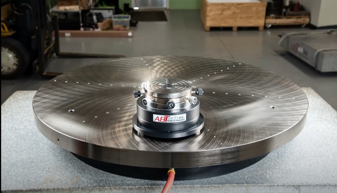
With proper selection and integration of high-performance brushless DC servo motors ABTech’s air bearing rotary tables provide ultra-smooth and precise rotary motion. With high torque, high performance motor drives, our motion experts will gather your specific requirements and work closely with our motor suppliers to create/select a motor drive that suits your specific application. Whether you need sub-micron position accuracy with minimal settle time and stringent following error specifications, high-speed constant motion, or a combination of both there is an ABTech rotary table that will meet your needs.
ABTech’s modular design approach facilitates multiple system configurations to optimize the price-for-performance required in your application. This approach allows the user to define the level of control desired for the most cost-effective solution. Our complete engineering services allow us to respond quickly to provide a solution to your O.E.M. requirements for ultra-precision rotary motion.
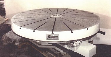
Air Bearing Rotary Tables, Table Top and Work Load are Supported on Air Bearings whose Freedom from Friction Contributes to Extremely High Positional Accuracy
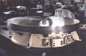
An Interlocking Switch is used when Motors are Incorporated to Prevent the Table Top from Moving when the Air Supply is Turned Off. When the Air Supply is Turned Off, the Table Top Sits Firmly on our Cast Base with an Extremely High Accuracy of Parallelism Between the Base and Table Top
Rotary tables specifically developed for use in Metrology applications. CMM tables, inspection tables, assembly tables. Range of sizes 100mm thru 5,000mm. Larger on request.
Air bearing rotary tables, when rotating, the table top and work load are supported on air bearings whose freedom from friction contributes to the extremely high positional accuracy. High precision needle roller bearing maintains radial accuracy.
Supplied with each table. On/off Switch controls the compressed air supply to the table. Interlocking ensures that the motor drive can only operate if the air supply is on. When air supply is off, table sits firmly on the base casting with extremely high accuracy of parallelism between the top surface and the underside of the base.
Air bearing stages are used where vibration-free motion is required, velocity needs to be highly constant, and optimum angular repeatability is requested.
Air bearings avoid friction, wear, and backlash effects. PIglide linear, rotary and spherical bearings are precision components that can be integrated and motorized for applications in OEM, industrial, and research markets.

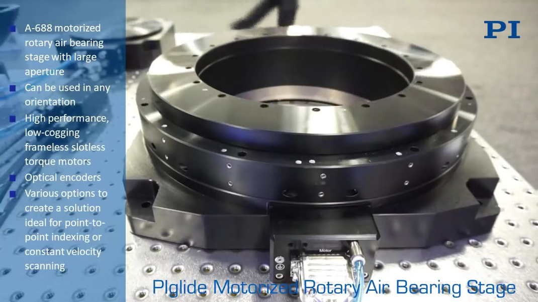
The PIglide RT series of nonmotorized passive rotary air bearings are designed for accuracy, precision, high stiffness, and ease of use. They can be used in any orientation and are easy to integrate with motors and encoders for complete positioning solutions.
The bearings of the RT series offer superior eccentricity, flatness, and wobble performance. Because they are completely friction-free, they exhibit no breakaway torque and no frictional resistance during operation. They are ideal for use in cleanrooms, require no maintenance or lubrication, and have unlimited lifetime.
Air bearings use a thin film of pressurized air to support a load, the same way the puck on an air hockey table "floats" on air. This type of bearing is called a "fluid film" bearing. Fluid film bearings have no solid-to-solid contact under typical running conditions; instead, a film of lubricating fluid (in our case pressurized air) forms a layer between the solid machine elements and serves to transfer forces from one to the other. To compare this with ball bearings, in ball bearings the balls are in constant contact with and form a solid bridge between the machine elements.
The fluid is able to transfer forces because as the fluid is pushed through the bearing gap it generates a pressure profile across the bearing area. The force the bearing can support is then:
The actual pressure distribution in the bearing varies based on the bearing design and other parameters but a good rule of thumb is to expect 30% efficiency.
For flat pads and rectangular bearings this calculation is quite straightforward, but for journal and spherical bearings we use a few other approximations to estimate load capacity.
Fluid film bearings offer a number of advantages over mechanical bearings. First, because there is no contact, air bearings do not suffer from wear or heat generation due to friction. They also exhibit no starting or running friction, even under their highest design loading. In addition, the fluid film acts to center and average out small scale errors in the components resulting in motion which can be more accurate than the individual bearing components. Air bearings also offer much higher stiffness than rolling element bearings because the air film fully supports the components, as opposed to balls or rollers which have point or line contact and are therefore limited due to Hertzian contact stiffness.
While most engineers are familiar with oil fluid film bearings - for example the crankshaft journal bearings in car engines - knowledge of air bearings is less abundant. Remembering our high school physics class, there are two basic types of fluids - liquids and gasses. In terms of fluid film bearings, the difference between these two is essentially the viscosity - liquids have much higher viscosity than gasses. When applied to a fluid film bearing, this difference has a number of implications.
First, lower viscosity means that for the same working pressure gas bearings have lower load capacity (liquid fluid film bearings typically support five times the load of gas bearings for the same pad area). Second, because of the extremely low viscosity of gasses, gas film bearings operate with essentially zero static and running friction where liquid fluid film bearings have much higher friction and pumping losses within the bearings, which can cause heat generation. And third, gas bearings require very tight bearing gaps for proper operation (10 µm for gas compared to up to 100 µm for liquid bearing) which translates into extremely high accuracy requirements on the components.
What this means for air bearings is that although they have a lower load capacity, gas bearings have essentially zero friction at all speeds and because the tight bearing clearances demand high accuracy components this results in extremely high accuracy motion. Another benefit is the cleanliness of using air as a lubricating fluid as opposed to oil, water, or another fluid. Since compressed air is very common in industrial environments it is probably the most often used gas, however other gasses such as nitrogen can be used where they are available (such as in clean room environments).
The first question is how to generate the pressurized supply of fluid for the bearing. There are two ways to do this - one is using an external pressurized supply (hydrostatic) and the other is to use the relative motion of the machine components to generate the pressure internally (hydrodynamic or "self-generating"). While hydrodynamic bearings are common for oil fluid film bearings, which generate internal pressures quite easily due to the relatively high viscosity of oil, it is much rarer to see this technique used for air bearings because the pressure generated is quite low (although PI Nelson Air has built bearings of this type for low load, high speed rotary applications such as optical scanners).
Our typical air bearings are hydrostatic (or in our case aerostatic) and use a compressed air supply to create the fluid film. This supply should be clean and regulated to a constant pressure - simple off the shelf air handling components are more than adequate for most applications to clean, dehumidify, and regulate the supply. Typical operating pressures run as low as 20 psi up to 120 psi depending on the stiffness, load capacity, and air consumption requirements.
After entering the bearing and being routed though internal passages, the next step is to feed the pressurized air to where it is needed - namely directly into the bearing gap. There are two basic ways to accomplish this, orifices and porous media. For orifices, the air flows through a small hole (typically .004" to .015" dia.) into the bearing area. Porous media bearings use a porous material (typically carbon, bronze, or steel) which the air penetrates through into the bearing area.
The relative benefits of each approach are debatable. While orifices typically do not generate as uniform a pressure profile as can be achieved with porous media, there are ways to improve the pressure profile using a technique called "pocketed compensation". Porous media feeding provides more inherent damping than orifices, however proper sizing of the orifices can adjust damping. Orifices can become plugged if a very large particle gets into the air supply (this is extremely rare), where the porous media acts as a filter for the air. However, because of this filtering effect, over time the porous media itself can become clogged (oil vapor in the air is particularly bad) and a clogged porous bearing is much more difficult to clear than a clogged orifice.
Orifice fed bearings can be made from one piece of material (particularly when using drilled nozzles) where porous bearings are necessarily made using varying materials and adhesives.
At PI Nelson Air we have used both orifice and porous media feeding. Most of our standard products use pocket compensated orifices, however our LB series of linear bushings use porous bronze. Our typical orifice bearings are made using a special technique we have developed to drill the small orifices directly into the bearing, instead of using pressed in or glued in jewel nozzles. We believe that this technique reduces cost and complexity while increasing long term stability and reliability. However, jeweled nozzles are used when the design precludes drilled nozzles either because of geometry or because especially small orifice sizes (.004" for example) are required.
Because of the very small gaps that are required for air bearings, the single most important factor in their manufacture is absolutely flawless geometry. Any variation in part size, straightness, squareness or out of roundness will result in a closing of the gap and will cause the bearing to lose its frictionless nature as well as degrade accuracy and load capacity. Typical tolerances on our rectangular bearings which run air gaps of ~0.0005" are part deviations less than ±0.0001" overall. This same tolerance applies over the entire length of the bearing, which for some models can be over 60".
In addition, the part geometry is what determines the accuracy of the final bearing motion - even though local deviations are averaged out by the air film, the overall accuracy is dictated by how well the parts are made. Because of this, PI Nelson Air has developed a variety of techniques and equipment which allow us to meet these stringent tolerances with repeatability and relatively low cost.
Air bearings offer the best of all worlds because they have excellent accuracy, precision and repeatability. They offer high accuracy because the components are manufactured with extremely tight tolerances and because of the air film"s averaging effects. Typical linear accuracies are 10 µin/in with maximum deviation of 100 µin/36 in. Rotary runout can be as low ±1 µin. Air bearings also offer extremely good tilt characteristics - 0.25 arcsec/in.
Because air bearings exhibit no stiction or running friction, the precision achievable is only limited by the abilities of the motor/controller/encoder. Positioning precision of ±1 encoder count can easily be achieved using linear motors.
The repeatability of air bearings far exceeds that of mechanical bearings for the simple reason that they have no contact or wear. Heat generation in mechanical bearings sometimes require "warm up" periods during which there is thermal movement. Also, the mechanical preload on roller bearings can vary with temperature and cause the bearings to operate differently (varying friction for example) and lack repeatability. When working at the highest accuracy levels, these effects can cause mechanical bearings to lose their accuracy from hour to hour, day to day, or month to month. Because the accuracy of our air bearings is built into its solid metal components (made from one type of material for uniform thermal expansion), they can operate for years without any degradation in accuracy. This way, a calibration done one day will "stick". They also can be run at top speed without any need for warm-up time (excluding motor heating effects) and maintain their best accuracy.
While some configurations of air bearings are self-preloading (e.g. journal bearings) others such as flat pads and linear rectangular bearings can benefit from preload. Air bearings can be used without any preload (such as a simple flat pad riding on a granite surface), however, in order to maximize the stiffness of the air bearing and help maintain constant air gap it is typical to preload it using one of four basic methods:
The simplest method is weight. Using a weight much heavier than the expected variation in the loading of the bearing preloads the air bearing so it rides at a smaller (and stiffer) air gap and makes it less prone to height variations. This method has the drawback of adding moving mass but can work very will with systems which already have a large amount of mass and low forces (such as parts inspection). Needless to say, this only works for bearings which operate horizontally.
The second method is using a vacuum preload. A vacuum is used to apply a preloading force to the air bearing (instead of using a weight). This is accomplished by providing an area of the bearing surface over which a vacuum is applied. Because vacuum is limited to around negative 14 psi (atmospheric pressure) and typical air bearing pressures are 40-80 psi the net effect is still a lifting of the bearing, even when the bearing and vacuum areas are equal. Vacuum preload enhances the stiffness and helps to maintain constant air gap, without adding unnecessary moving mass. The main drawbacks to this method are the need for a larger bearing area to accommodate both pressure and vacuum and the requirement of a vacuum source. This method has been used successfully in many applications, especially for flat pads and planar systems which do not lend themselves to other forms of preload.
The third method of preloading is magnetic preload. Magnetic attraction between a magnet on the moving part and a magnetic material on the stationary part of the bearing loads the bearing and adds stiffness. This configuration works well for linear bearings and can be very cost effective because it reduces the tolerances required for the air bearing components (as compared to air bearing preloaded systems). However, because many air bearings are made from nonmagnetic materials, it requires adding other materials to the bearing (such as iron). Another drawback is that at high speeds, the magnet generates eddy currents in the iron which oppose the motion and add a drag force (eliminating the "zero friction" of air bearings). However, in many applications magnetic preload provides an effective method of preloading air bearings.
The final method is opposing air bearing preload. This method uses opposing air bearings to preload each other. This method provides twice the stiffness of a single air bearing, although the load capacity is reduced by almost half (the other preload methods also reduce load capacity, based on the amount of force they apply) and is very effective in producing the most accurate and reliable air bearings. Because there are two air bearings working in parallel it also has the effect of averaging any errors on either bearing (centering) and can therefore deliver higher accuracy than any other method. In addition, air bearing preloaded bearings can be operated in any orientation. The majority of PI Nelson Air"s standard bearings use this method because we believe it provides the highest quality, accuracy and versatility. However, this method does require higher accuracy components with more precision surfaces.
Now that you understand the basics of how air bearings work, here are some of the most common configurations for using them to create motion with a variety of degrees of freedom. If you have any additional questions, please contact us and we would enjoy assisting you.
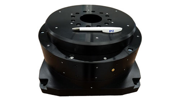
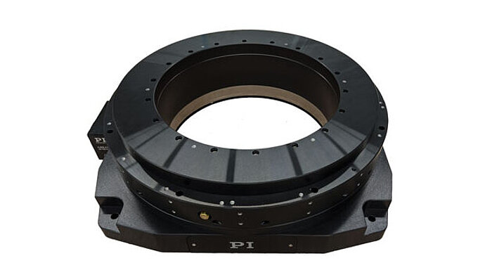
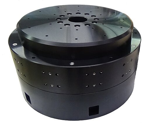
The design of the ABRS series direct-drive rotary stage has been optimized to minimize stage height. The low profile of the stage reduces the effective working height of the system, minimizing "stack-up" related errors. In addition to the low overall height, the ABRS series provides a clear aperture that can be used for product feed-through, laser beam delivery, cable clearance or application-specific requirements.
The ABRS design features large air-bearing surfaces for high stiffness and load capacity, producing not only excellent axial and radial error motions but outstanding tilt error motion, as well. The resultant face error motion is significantly better than other rotary air-bearing tables and spindles, greatly benefiting applications requiring exceptional planar performance.
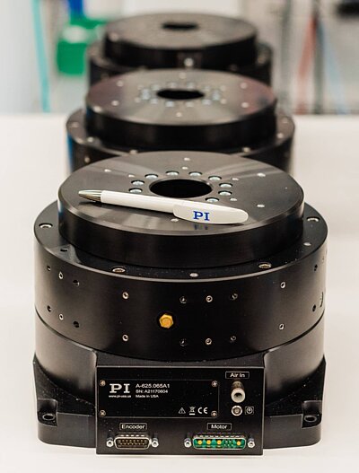
AUBURN, Mass., Feb. 1, 2023 /PRNewswire-PRWeb/ -- PI is introducing a new series of direct-drive, ball bearing rotary stages to supplement their A-62x series of air bearing spindles. The V-62x stage family is designed for 24/7 applications that require high precision motion with eccentricity and flatness deviations below 1µm and high stiffness. The new rotary stage family can be mounted and operated in any orientation, a critical feature for many industrial automation applications.
Based on PI" s extensive knowledge in the design and manufacture of ultra-high-precision rotary tables with air bearings, the new V-62x mechanical bearing rotary stages were designed to provide exceptional performance regarding travel accuracy, flatness, and wobble. The ultra-precise deep groove ball bearings are preloaded and lubricated prior to delivery, meaning they are maintenance-free for the whole lifetime of the rotation stage.
Three-phase torque motors are at the heart of the direct-drive rotary stages, transmitting torque directly and friction-free to the motion platform. Advantages of a direct-drive design over a worm gear drive are higher velocity and acceleration, faster response, as well as the total lack of backlash and no friction in the drive train.
Single and multi-axis, ACS-based motion controllers and servo drives are available for single axis applications of the rotary stages or multi-axis, multi-degree-of-freedom sub-assemblies — also available from PI.
PI is a privately held, global leading company that designs and manufactures world-class precision motion and automation sub-systems including air bearings, hexapod micro-positioning robots, and piezo drives at locations in North America, Europe, and Asia. The company was founded 5 decades ago and today employs more than 1,500 people worldwide. PI"s customers are leaders in high-tech industries and research labs, in market segments such as photonics, life-sciences, semiconductors, industrial automation and aerospace.
Air bearings (also known as aerostatic or aerodynamic bearings) are fluid bearings that use a thin film of pressurized gas to provide a low friction load-bearing interface between surfaces. The two surfaces do not touch, thus avoiding the traditional bearing-related problems of friction, wear, particulates, and lubricant handling, and offer distinct advantages in precision positioning, such as lacking backlash and static friction, as well as in high-speed applications.Space craft simulators now most often use air bearings3-D printers are now used to make air-bearing-based attitude simulators for CubeSat satellites.
A differentiation is made between aerodynamic bearings, which establish the air cushion through the relative motion between static and moving parts, and aerostatic bearings, in which the pressure is being externally inserted.
Gas bearings are mainly used in precision machinery tools (measuring and processing machines) and high-speed machines (spindle, small-scale turbomachinery, precision gyroscopes).
Aerostatic bearings: the gas is externally-pressurized (using a compressor or a pressure tank) and injected in the clearance of the bearing. Consequently, aerostatics bearings can sustain a load even in absence of relative motion but require an external gas compression system, which induces costs in terms of complexity and energy.
Aerodynamic bearings: the gas is pressurized by the relative velocity between the static and moving surfaces in the bearing. Such bearings are self-acting and do not require an external input of compressed gas. However, mechanical contact occurs at zero speed, requiring a particular tribological consideration to avoid premature wear.
Hybrid bearings combining the two families also exist. In such cases, a bearing is typically fed with externally-compressed gas at low speed and then relies partially or entirely on the self-pressurizing effect at higher speeds.
Gas film is pressurized by grooves machined on one of the surfaces, achieving high load capacity and stability. The usual groove patterns are herringbone-shaped, spiral or straight (step bearings)
Pressurized gas acts as a lubricant in the gap between bearing moving parts. The gas cushion carries the load without any contact between the moving parts. Normally, the compressed gas is supplied by a compressor. A key goal of supplying the gas pressure in the gap is that the stiffness and damping of the gas cushion reaches the highest possible level. In addition, gas consumption and uniformity of gas supply into the gap are crucial for the behaviors of aerostatic bearings.
Dead volumes refer in particular to chambers and canals existing in conventional aerostatic bearings in order to distribute the gas and increase the compressed pressure within the gap. The cavity inside porous (sintered) gas bearings are also attributed to dead volume.
With conventional single nozzle aerostatic bearings, the compressed air flows through a few relatively large nozzles (diameter 0.1 – 0.5 mm) into the bearing gap. The gas consumption thus allows only some flexibility such that the bearing"s features (force, moments, bearing surface, bearing gap height, damping) can be adjusted only insufficiently. However, in order to allow a uniform gas pressure even with only some nozzles, aerostatic bearing manufacturers take constructive techniques. In doing so, these bearings cause dead volumes (non-compressible and thus weak air volume). In effect, this dead volume is very harmful for the gas bearing"s dynamic and causes self-excited vibrations.
The pre-pressured chamber consists of a chamber around the centralized nozzle. Usually, this chamber"s ratio is between 3% and 20% of the bearing"s surface. Even with a chamber depth of 1/100 mm, the dead volume is very high. In the worst cases, these air bearings consist of a concave bearing surface instead of a chamber. Disadvantages of these air bearings include a very poor tilt stiffness.
Typically, conventional aerostatic bearings are implemented with chambers and canals. This design assumes that with a limited amount of nozzles, the dead volume should decrease while distributing the gas within the gap uniformly. Most constructive ideas refer to special canal structures. Since the late 1980s, aerostatic bearings with micro canal structures without chambers are manufactured. However, this technique also has to manage problems with dead volume. With an increasing gap height, the micro canal"s load and stiffness decreases. As in the case of high-speed linear drives or high-frequency spindles, this may cause serious disadvantages.
Laser-drilled micro nozzle aerostatic bearings make use of computerized manufacturing and design techniques to optimize performance and efficiency. This technology allows manufacturers more flexibility in manufacturing. In turn this allows a larger design envelope in which to optimize their designs for a given application. In many cases engineers can create air bearings that approach the theoretical limit of performance.
Rather than a few large nozzles, aerostatic bearings with many micro nozzles avoid dynamically disadvantageous dead volumes. Dead volumes refer to all cavities in which gas cannot be compressed during decrease of the gap. These appear as weak gas pressure stimulates vibration. Examples of the benefits are: linear drives with accelerations of more than 1,000 m/s² (100 g), or impact drives with even more than 100,000 m/s² (10,000 g) due to high damping in combination with dynamic stiffness; sub-nanometer movements due to lowest noise-induced errors; and seal-free transmission of gas or vacuum for rotary and linear drives via the gap due to guided air supply.
Micro-nozzle aerostatic bearings achieve an effective, nearly perfect pressure distribution within the gap with a large number of micro nozzles. Their typical diameter is between 0.02 mm and 0.06 mm. The narrowest cross-section of these nozzles lies exactly at the bearing"s surface. Thereby the technology avoids a dead volume on the supporting air bearing"s surface and within the area of the air supplying nozzles.
The micro nozzles are automatically drilled with a laser beam that provides top-quality and repeatability. The physical behaviors of the air bearings prove to have a low variation for large as well as for small production volumes. In contrast to conventional bearings, with this technique the air bearings require no manual or costly manufacturing.
highest-possible flexibility of the air bearing properties: with a particular gap height, it is possible to optimize the air bearing such that it has, for example, a maximum load, stiffness, tilt stiffness, damping, or a minimum air consumption (respectively also in combination with others);
multi-approved highest precision of all air bearings, e.g. in the measurement technology due to slightest movements (<< 2 nanometer) through physical, lowest-possible self-excited vibrations;
considerably higher tilt stiffness than conventional air bearings such that the air within the gap flows through canals from the loaded to the unloaded areas away;
Some of these advantages, such as the high flexibility, the excellent static and dynamic properties in combination, and a low noise excitation, prove to be unique among all other aerostatic bearings.
In addition, there are also rectangular bearings with a fixed mounting (joint-less) for guidances with highest stiffness for highest accuracy or highest dynamic.
Furthermore, there are also air bearings with integrated vacuum or magnetic preloads, air bearings for high temperatures with more than 400 °C, as well as ones manufactured with alternative materials.
Wearless operation, durability. Air bearings operate contact-free and so without abrasion. The only friction results from airflow between the bearing surfaces. Thus, the durability of air bearings is unlimited if they are designed and calculated correctly. Roller bearings and friction bearings have a high degree of friction when used at high speed or acceleration, causing a positive feedback loop where high abrasion decreases precision, which in turn causes greater wear, leading to their eventual failure.
Guiding, repeatability, and position accuracy. In the chip production and when positioning at the back-end, repeatability accuracy of 1-2 μm must be reached with the wire bonder. At the die bonder, even 5 μm must be achieved. With such a precision, roller bearings reach their physical limit without a lower acceleration. At the front end (lithography), air bearings are already established.
Cost advantage and repeatability. When applied in series, gas bearings can have a cost advantage over roller bearings: the production of a roller-guided high-frequency spindle is – according to a manufacturer – about 20% more expensive than air-guided spindles.
Environmental purity. Because they do not require the use of oil for their lubrication and are frictionless, gas bearings are suited for applications requiring a low contamination of the working fluid. This is a critical aspect to the pharmaceutical industry, nuclear fuel processing, semi-conductor manufacturing and energy conversion cycles.
Self-excited vibration. In journal bearings, self-excited vibration can appear past a given speed, because of the cross-coupled stiffness and low damping of gas lubrication. This vibration can lead to an instability and threaten the gas bearing operation. Precise dynamic computations are required to ensure a safe operation within the desired speed range. This kind of instability is known as "half-speed whirl" and affects particularly aerodynamic bearings.
Tight manufacturing tolerances. In order to carry sufficient load and avoid the instability mentioned above, tight tolerances are required in the clearance between bearing surfaces. Typical clearances ranging from 5 μm to 50 μm are required for both aerodynamic and aerostatic bearings. Consequently, air bearings are expensive to manufacture.
Clean environment. Because of their small clearance, gas-lubricated bearings are sensitive to the presence of particulates and dust in the environment (in the case of aerodynamic bearings) and externally-pressurized gas (aerostatic bearings).
Gas-lubricated bearings are usually modeled using the Reynolds equation to describe the evolution of pressure in the thin film domain. Unlike liquid-lubricated bearings, the gas lubricant has to be considered as compressible, leading to a non-linear differential equation to be solved.
Numerical methods such as Finite difference method or Finite element method are common for the discretization and the resolution of the equation, accounting for the boundary conditions associated to each bearing geometry (linear-motion, journal and thrust bearings). In most cases, the gas film can be considered as isothermal and respecting the ideal gas law, leading to a simplification of the Reynolds equation.
In order to provide confidence and for the first investigations, an initial conversion from a conventional oil-guided turbo charger into air-guided was done. For a real future version, the use of results obtained from high-temperature solutions, mass products (proved production costs) and high-frequency spindles (know-how of dynamic background) will be very helpful.
In terms of the measurement of wafers and flat panels, it is very important to place the sensor chip precisely and without any contact along the surface. Therefore, the chip is integrated directly into the bearing"s surface. The maximum distance tolerance to the surface which refers to the gap variation of the air bearing, is smaller than 0.5 μm. When placing the air bearing with the sensor chip, they must not touch the wafer surface being measured. As for the up-and-down movement, a pneumatic piston is used which is, for repeatability reasons, also air-guided. The preload of the air bearing and thus the gap height are also adjusted with this piston.
For the electrical testing of wafers the chuck can be lifted stick-slip-free up to 3 mm. The needed contact force for the probe is adjustable and independent from stroke. The lift drive is based on a voice coil motor; the guidance is air-guided. An air-guided pneumatic piston between the chuck and the drive limits the contact force.
The filigree structure enables through light measurements for the 300 nm chip production with the utmost precision of less than 1 nm. In particular, the air bearings are designed for lowest air consumption with the highest stiffness.
The High-accelerated Doppler drive supports and guides a carbon fiber mirror (surface 500 mm x 250 mm) with an acceleration of up to 300 m/s² and a flexible movement profile with high precision. The solution consists of an air-guided drive: The beam (length 900 mm), which is fixed at the mirror, is manufactured of carbon fibre and carries the magnets of the linear motors. Cables/tubes (motor, air bearing, measurement system) do not move in order to avoid breakages due to high load cycles. The air-bearings are absolutely insensitive against geometric fluctuation as a result of a temperature change.
Beside the performance, the reliability is extremely important for a production machine. The air-guided solution is designed to be statically determined. The iron-core linear motor and piston bearings achieve the preload for the air bearings. Thereby, the drive is easy to assemble and insensitive against geometric variations, for instance through temperature influences or the disposition of the machines.
Fat- and oil-free drives for respirators, stick-slip-free movements of scanners or a high rotary speed of large rotors have all been achieved with air bearings.
High rotary speed (> 5.5 Hz / 330 rpm), low operation costs, no noise, large inner rotor diameter (> 1 m), small weight of rotor and frame, tilt possibility of the rotor as well as a high reliability. Besides a direct drive, a belt drive is also possible.
Primarily, stick-slip-free movements and/or smallest forces are required. The air bearing technology is predestinated for fat/oil-free high-dynamic movements with short strokes.
With air-guided units, optical components can be arranged to have the same diameter on a rotary table. The air bearing with vacuum preload and a constant bearing gap height floats contact-less on top of the rotary table.
The linear slider, which is air-guided and statically determined, guarantees a high-precision positioning of the optical component before grinding. The self-aligning process is done without friction or force. When clamped the component retains its position for further manufacturing in the sub-micrometer-range.
When transporting solar panels for satellites in a launching rocket, these must be folded. After reaching orbit, they unfold via a spring mechanism, weightlessly and without friction. This process requires prior testing on Earth due to reliability reasons. During the testing design, the solar panels are hung on magnetic preloaded air-bearings that compensate for gravity. In doing so, the unfolding movement process is carried out with a minimum friction impact which means that the solar panels are tested at close to reality. Moreover, the design offers absolutely maintenance-free handling with equal sequential movements.
The air-bearing components (diameter 34 mm) with integrated magnets are so small such that they are able to glide contact-free along conventional rolled sheet plates smoothly and with a bearing gap height of about 25 μm. The holding force of an air bearing for one solar panel averages 600 N. This force is achieved by an equal distribution of the load on 16 single air bearing elements. The unfolding process of the solar panels has been developed for an area of 21 m x 2.5 m.
The permanent magnetic preloaded air-bearing guidance system may be used for many types of hanging transportation movements as well as for many other applications, such as for instance for the stick-slip-free positioning of components during assembly.
Schwartz, Jana L.; Peck, Mason A.; Hall, Christopher D. (2003-07-01). "Historical Review of Air-Bearing Spacecraft Simulators". Journal of Guidance, Control, and Dynamics. 26 (4): 513–522. Bibcode:2003JGCD...26..513S. doi:10.2514/2.5085.
Nemanja Jovanovic, et al. Design and Testing of a Low-Cost, Open Source, 3-D Printed Air-Bearing-Based Altitude Simulator for CubeSat Satellites. Journal of Small Satellites Vol. 8, No. 2, pp. 859–880 (2019). https://jossonline.com/letters/design-and-testing-of-a-low-cost-open-source-3-d-printed-air-bearing-based-attitude-simulator-for-cubesat-satellites/
Schulz, Bernd (1999). Herstellung von aerostatischen Lagern mit Laserendbearbeitung [Production of Aerostatical Bearing with Laser Processing] (Ph.D.) (in German). Germany: VDI Verlag. ISBN 3-18-352502-X.
Klement, Joachim (2009). Funktionsweise der LuftlagerIn:Technologie der elektrischen Direktantriebe [Function analysis of air bearings In:Technology of electrical direct engines]. Germany: Expert Verlag. ISBN 978-3-8169-2822-5.
Germany DE4436156, J. Heinzl; M.Muth; B. Schulz, "Aerostatische Lager und Verfahren zur Herstellung eines aerostatischen Lagers [Aerostatical bearings and procedures for the production of aerostatical bearings]", published 10 October 1994, issued 10 October 1994, assigned to J. Heinzl; M.Muth; B. Schulz
Schroter, Andreas (1995). Ausgleichsvorgänge und Strömungsgeräüsche bei aerostatischen Lagern mit flächig verteilten Mikrodüsen [equalizing procedures and current noize at aerostatical bearing with spread micro-nozzles]. Germany: VDI Verlag. ISBN 978-3-18-324501-7.
Gerke, M. (1991). Auslegung von ebenen und zylindrischen aerostatischen Lagern bei stationären Betrieb [construction of plain and cylindrical aerostatical bearings bei stationary operating]. germany: tu-münchen. ISBN 978-3-8316-0631-3.

This compact closed-loop direct drive rotary table uses a 3-phase motor for maintenance free, frictionless power transmission. It comes in two variations, standard and with holding brake.
Application video of the silent ultrasonic piezo motor rotary stage in a Leica Theodolite and Principle Design of the PILine drive used in the M-660 PILine� rotary stage
This miniaturized closed-loop rotary positioner is driven by an ultrasonic direct-drive motor and provides high rotational velocity up to 3 revolutions / second. An optical encoder is integrated for direct position measurement and feedback with 35 �rad resolution.
Q-motion series miniature rotation stages are driven by inertia-type piezo motors. These miniaturized positoining tables are direct-driven, backlash free and provide micro-radian resolution. The self-locking design requires no holding current and provides excellent long-term stability. Three different diameters are available: 14 mm, 22 mm and 32 mm.
PI"s air-bearing rotation stages provide the highest accuracy and smoothest motion of any commercially available rotation stage. With standard and custom designs these stages are designed for reference class applications.
The PI miCos line of goniometers and rotation stages is specialized on miniature stages with different motor drives (belt-drives, worm-gear drives) and also on ultra-high precision stages with torque motors, direct metrology and air bearings.
There is no theoretical limit to the speed of a linear engine because there is no contact. However, speed is typically limited by the mechanical bearings. For example, the maximum speed for linear control systems with rails and guide cars is usually limited to 5m/s. Therefore, the speed for linear motors in most applications is limited to 5m/s. The use of ceramic ball bearings allows speeds of up to 10m/s. By using air bearings, higher speeds can also be possible.
Linear Motors can be used in cleanroom environments. In fact, many front-end semiconductor applications have linear motors in use. In wafer manufacturing plants, high-precision lithography machines, for example, use linear motors in XY positioning tables with very high accuracy (nanometer resolution) and submicron accuracy in cleanroom classes according to ISO 2.

The face grinding process depends on high-precision rotary table spindle with a large axial load capacity. This paper develops an ultra-precision rotary table spindle with externally pressurized air bearings consisting of a double-pad thrust bearing and a journal bearing; a vacuum clamp system is designed to locate and hold the workpiece. The dynamic model for the rotor-bearing system has been established by using the Reynolds equation and the rigid-body dynamic theory considering five degrees…Expand


 8613371530291