
fibro rotary table free sample
A turbo among rotary tables – the new FIBRODYN DA direct driven rotary tables with torque motor are optimally suited for all handling and assembly applications that require the shortest indexing times and flexible positioning. Thanks to its measuring system directly in the rotary table axis, any position can be moved to with the highest precision. The slim design with its very space-saving, compact construction and its fitted boreholes makes it very easy to integrate the rotary tale into your system. FIBRODYN DA is also available as decentralized stand-alone solution with integrated control. In this version, it offers the ideal opportunity to save a separate external NC control to minimize the implementation and start-up costs and to realize small machines without complex peripherals. The rotary tables are lifetime lubricated and maintenance free.

A powerhouse with an extremely large center hole and very flat design at an optimum price — the FIBROMAT heavy-load positioning tables from FIBRO. When large and heavy fixtures have to be positioned dynamically and precisely, the FIBROMAT modular heavy-load positioning table is the optimum solution. It fits perfectly into automobile body in white, as the heart of work piece storages or in honing centers, for example. The maintenance-free rotary table with lifetime lubrication is driven by reliable spur gear drive.

ELECTROMECHANICAL UNIVERSAL ROTARY TABLES An extremely long life time and shortest cycle time with an excellent precision and no need for maintenance - these are important aspects to any production line. FIBROTOR® rotary tables combine all of them and offer as an additional highlight up to five years warranty. Thanks to its completely new developed control cam, energy consumption drops by 20 %. Alternatively, higher masses can be moved, shorter indexing time can be realized or a smaller rotary table can be used. Indeed, FIBROTOR® rotary tables may be used as assembly tables; welding, positioning or storing tables; in packaging, printing, labelling or laser machines, as well as for light cutting. FIBROTOR® rotary tables work without elastic drive elements that tend to get worn out and enable highly precise positioning and repeatability. Extremely short positioning times ensure excellent productivity.
An extremely long life time and shortest cycle time with an excellent precision and no need for maintenance - these are important aspects to any production line. FIBROTOR® rotary tables combine all of them and offer as an additional highlight up to five years warranty. Thanks to its completely new developed control cam, energy consumption drops by 20 %. Alternatively, higher masses can be moved, shorter indexing time can be realized or a smaller rotary table can be used.
Indeed, FIBROTOR® rotary tables may be used as assembly tables; welding, positioning or storing tables; in packaging, printing, labelling or laser machines, as well as for light cutting. FIBROTOR® rotary tables work without elastic drive elements that tend to get worn out and enable highly precise positioning and repeatability. Extremely short positioning times ensure excellent productivity.
FIBRO can offer you the suitable rotary table type for the application at hand, with the FIBROTOR® product range. FIBRO provides highly accurate solutions, specifically made to satisfy each customer"s demands, from the FIBROTOR® EM line, or an attractively priced universal rotary table from the FIBROTOR® ER line, which serves as a great basic model and which can be supplied in short term thanks to a maximum degree of standardization. The rotary indexing ring FIBROTOR® RT is perfect for any application which requires a large center hole. For flexible positioning FIBROTOR® EM and FIBROTOR® RT are available as NC type. All FIBROTOR® rotary tables can be used horizontally and vertically.

Sensors are the basis for precise visualization, optimization, measurement, inspection and tracing of all punching and forming processes. FIBRO sensors have been specifically developed for punching and forming. FIBRO offers a wide range of sensors in various designs, complete with the matching installation equipment.
Our hydraulic Flex Cam System is suitable for all applications where conventional tool slides are limited with regards to the working angle. Forming and punching processes are possible against the relative movement of the tool. This allows a further reduction in the required number of tools.
For many years FIBRO earned a reputation for excellence in the selection of standard parts in the field of cutting, stamping tools and machine tools. So it was only logical to add a similar range for mould making
With its products from the Business Area Rotary Tables, FIBRO has succeeded in becoming well known around the world. In this area, we offer the largest selection of rotary indexing tables available from a single source. Starting with a pneumatic rotary table in 1960, this product line has developed into a programme that today includes more than 150 different models.
Rotary indexing tables from FIBRO are used as swivel axis or axis for positioning as well as workpiece carrier in machine tools as well as in assembly applications. In the mean time, thousands of units have been incorporated as essential components into highly productive machines around the world. The quality, the performance and the large product line meet whatever requirements our customers have.
With its international presence, FIBRO is a partner in your production and provides competent solutions for tasks involving rotary indexing tables and NC technology – worldwide. Experts are at your disposal from as early as the planning phase of a project and continue to work with you as the project progresses.ROTARY TABLES FOR MACHINE TOOLS
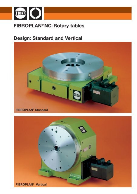
FIBROPLAN rotary tables are equipped with a backlash-adjustable worm drive for machine tools for universal positioning. Rotary and multiple-axis machining (simultaneous operation) is possible. The application of high-resolution measuring systems and the special design features with high-precision, rigid bearing results in high positioning accuracy.
FIBROMAX 2.0 second-generation heavy-duty positioning table convinces with high rigidity and energy efficiency. With the FIBROMAX 2.0 series, FIBRO presents a completely reworked series of its high-performance XXL rotary shift tables. Compared to the first generation, the bearing diameter and thus the rigidity of the heavy-duty positioners have grown significantly - and this at virtually unchanged costs. Constantly increasing demands on the mechanical processing of complex components for wind turbines, rolling bearings, turbines, gearboxes and construction machines were the trigger for the development of this new heavy-duty concept.
A turbo among rotary tables - the new FIBRODYN DA direct driven rotary tables with torque motor are optimally suited for all handling and assembly applications that require the shortest indexing times and flexible positioning. Thanks to its measuring system directly in the rotary table axis, any position can be moved to with the highest precision. The slim design with its very space-saving, compact construction and its fitted boreholes makes it very easy to integrate the rotary tale into your system. FIBRODYN DA is also available as decentralized stand-alone solution with integrated control. In this version, it offers the ideal opportunity to save a separate external NC control to minimize the implementation and start-up costs and to realize small machines without complex peripherals. The rotary tables are lifetime lubricated and maintenance free.
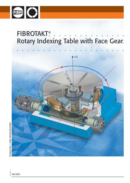
In 1962, FIBRO launched the world"s first indexing table with face gear for the international market: the FIBROTAKT. It was developed for high-precision indexing and is able to withstand high machining loads. A locking mechanism in the FIBROTAKT"s face gear ensures high precision and rigidity over the long term. A range of designs and drive types makes it possible to find the perfect solution for any application. The FIBROTAKT built-in indexing table for rotary transfer machines combines the shortest possible cycle times - even with heavy setups - with maximum precision and rigidity.
Our rotary tables for automation systems can be used as swivelling or positioning axes, as tool carriers, or put to use in a number of assembly applications. With incredible machining power and the shortest possible cycle times, not to mention the very highest standards of precision, we can boost the efficiency of your production processes, no matter the application.
An extremely long life time and shortest cycle time with an excellent precision and no need for maintenance - these are important aspects to any production line. FIBROTOR® rotary tables combine all of them and offer as an additional highlight up to five years warranty. Thanks to its completely new developed control cam, energy consumption drops by 20 %. Alternatively, higher masses can be moved, shorter indexing time can be realized or a smaller rotary table can be used.
Indeed, FIBROTOR® rotary tables may be used as assembly tables; welding, positioning or storing tables; in packaging, printing, labelling or laser machines, as well as for light cutting. FIBROTOR® rotary tables work without elastic drive elements that tend to get worn out and enable highly precise positioning and repeatability. Extremely short positioning times ensure excellent productivity.
The compact rotary table FIBROTOR VR.NC is designed for flexible movement tasks and is freely programmable. Thus, the series is ideal for use in automated assembly processes. With an optimal sealing concept and high performance data, the FIBROTOR VR.NC. can also be used as a rotary drum version (horizontal axis of rotation).
A powerhouse with an extremely large center hole and very flat design at an optimum price  the FIBROMAT heavy-load positioning tables from FIBRO. When large and heavy fixtures have to be positioned dynamically and precisely, the FIBROMAT modular heavy-load positioning table is the optimum solution. It fits perfectly into automobile body in white, as the heart of work piece storages or in honing centers, for example. The maintenance-free rotary table with lifetime lubrication is driven by reliable spur gear drive.

There are key differences between fixed-position indexing tables and closed-loop position indexing tables. Here we review them and how to control for maximum accuracy.
Indexing tables come in an array of versions with different speed and dwell settings to satisfy tasks in machine-tool handling, stamping, medical-device assembly, and bottle capping. These tables use mechanical drives, variable frequency drives (VFDs), programmable servo setups, and direct drives. Some mechanical cam-based indexers convert input into intermittent output by transmitting motion through a precision barrel cam. Versions that work as fixed-position indexers have the motion profile cut directly into the cam for engaging followers. Such mechanical drives are often simpler and more robust for set tasks than other options. That said, some indexing tables now integrate VFDs and even servos to deliver the intermittent movements of indexing with more flexibility where production requires it.
In fact, the migration to VFDs has made it possible to use inverter-duty single-speed ac motors that accept VFD-based control. This enables more versatile indexing functions from constant-lead-cut cams thanks to closed-loop positioning. Such flexible systems differ from fixed-position indexers because (as mentioned) fixed-position indexers have the whole motion profile cut directly into the cam. In contrast, newer closed-loop positioning indexers use a VFD to control the motion profile. One caveat: While this is a more flexible setup, it’s also easier to incorrectly program such indexers … and even damage the cam followers and cam in the process. These are considerations when choosing the most suitable design for an application needing indexing …
This is an extremely accurate and repeatable system, because the cam followers are preloaded against the cam (with cam perpendicular to the rotation). There’s no added cost for encoder feedback.
Cam-based setups that run at constant speed convert constant input-drive motion (from a motor) into intermittent motion output through mechanical means. Indexer-part manufacturers digitally shape the cam upfront so it doesn’t cause jerk but instead makes soft and shockproof strokes optimized for the task at hand. Most such cams go into assemblies to maintain secure mounting to the output table (sometimes called a dial). The motor is usually a three-phase brake motor that transmits power through a chain wheel, belt wheel, or gear reducer to the table driveshaft. This connects directly to the barrel cam to turn cam followers and output flange. The flange sits inside a wire-bearing assembly free of backlash, and the whole drive is sealed against ingress.
As mentioned, flexible indexer designs use either a servomotor setup or an ac-motor setup with an encoder. Indexing tables that run off a VFD can cycle the motor driving the cam at a preset speed to a preset dwell and then stop. That lets the dial park at a location for seconds to hours — to allow processes at a station to complete before advancing a workpiece to the next station, for example. The encoder tracks camshaft position for high positioning accuracy. Some designs have the output dial ride a high-precision four-point bearing assembly preloaded against runout. Some manufacturers seal the whole drive against dust and moisture ingress.
The drawbacks of the other flexible indexer setup — that based on programmable servos — have already been mentioned. But to address a major issue for applications that need the highest level of programmability, some manufacturers design their servo-based programmable index tables so they’re identifiable by all robot brands and controls.
Note that cams provide mechanical benefits even in these forms that rely on controls for some motion profiling. Consider how these indexer setups have a gear reducer that connects the motor to the barrel cam’s input shaft, but the barrel cam rotates the top dial through cam followers with a rigid zero-backlash connection. This direct connection between the table’s rotating dial and cam eliminates the focus during design sizing on toque output for geared linkages. Instead, the machine builder can work with the manufacturer to size the cam drive to the total system and payload moment of inertia. That ensures the kinematic assembly of the indexing table withstands the application’s inertia loads without issue.

Every component in a production system is highly stressed and will become prone to glitches at some point. FIBRO is following the strategy of recognizing faults before they occur. Not only faults relating to rotary tables such as wear, also faults on the outside that can affect the machine such as a crash. The technical term for this is called “Predictive Maintenance” (PM). High precision sensors monitor the condition of a rotary table, collect all data accumulated in the production process and warns you if a parameter doesn’t add up – for example for inconsistent oil temperature, fill level, quality or for a crash. Further parameters such as overload and imbalance are currently tested. In doing so it is possible to swap spare and wearing parts before a rotary table failure, or even offer suggestions on how to improve the processes and increase productivity.
FIBRO is working on a study and in 2017 will present the prototype of an integrated PM-system. With this, rotary tables cannot only collect and access data, but also learn from one another. This system is internet-based. The controls and maintenance functions via Wi-Fi with the help of any end device. The system works based on highly complex mathematical algorithms and equation systems with over 100 variables per mathematical equation. A connection to almost all production systems is possible via a standard interface such as, for example, OPC-UA. Intelligent rotary tables do not only allow processes to be monitored and faults to be determined in advance, but they also allow faults to be analyzed afterwards. Furthermore, after a fault, e.g. caused by a crash, the “health condition” of the rotary table will be checked automatically. As a result, downtimes and repair costs can be kept to a minimum. Manufacturer specifications for maintenance, independent from the use of the rotary table, are automatically monitored and the intervals for necessary inspection are displayed.
The collected rotary table data on the PM system helps users to better understand the manufacturing process and allow further product improvements. Intelligent controls and handling large quantities of data processed via a smart data concept can pose a challenge. The data doesn’t reveal anything itself, so it is important to assess, to interpret the tsunami of data and to draw conclusions on the further conduct of the rotary table – in order to, in turn, gain concrete suggestions for improvements from it.
Pure monitoring of condition without an interpretation of data is according to a survey among FIBRO customers, rather “nice to have”. Above all it is about better understanding the behavior of a rotary table throughout its life cycle and thus ensuring a stress-free production process. Process data documentation is also important for the customer. The condition data captured by the sensors can be combined with information from corporate planning and management or customer management. From this, many measures can be derived for purchasing, quality and sales.
At the moment, predictive monitoring of rotary tables is still in the development stage, but once again, FIBRO is a pioneer and trailblazer for intelligent solutions.
A powerhouse with an extremely large center hole and very flat design at an optimum price — the FIBROMAT heavy-load positioning tables from FIBRO. When large and heavy fixtures have to be positioned dynamically and precisely, the FIBROMAT modular heavy-load positioning table is the optimum solution. It fits perfectly into automobile body in white, as the heart of work piece storages or in honing centers, for example. The maintenance-free rotary table with lifetime lubrication is driven by reliable spur gear drive.

FIBROPLAN ®1 · 11317 · 2001 · 1 °11th EditionThis edition makes all previous catalogues invalid. We reserve the right to make further modifications relevant to technical developments.
IndexFIBROPLAN – Overview – 5Technical DescriptionFIBROPLAN Standard + Vertical 6/7Measuring System and Motor Arrangements 8Ordering Code 9PageDesign Standard · Program summary 11Technical data and dimensionsNC-Rotary Table NC 1.02 12/13NC 1.03 14/15NC 1.04 16/17NC 1.05 18/19NC 1.06 20/21NC 1.07 22/23NC 1.08 24/25NC 1.09 26/27NC 1.10 28/29Design Vertical · Program summary 31Technical data and dimensionsNC-Rotary Table NC 2.01 32/33NC 2.03 34/35NC 2.04 36/37NC 2.05 38/39NC 2.06 40/41NC 2.07 42/43NC 2.08 44/45NC 2.09 46/47NC 2.10 48/49Technical descriptionFIBROPLAN – Combination models with multiple axes 50–53Accessories 54Model Definition Chart 55Formulae 56/57Determination of moment of inertia 581 · 11318 · 2001 °3
FIBROPLAN ® – Overview –The well-graded range of FIBRO-PLAN NC-Rotary Tables is characterizedby the very extensive capabilitiesof the rotary table movement andangular positioning, both under fullCNC-control. FIBROPLAN tables areused on machine tools of diversetype and description, with the controlof their rotational axis provided eitherby an additional control axis of themaschine’s CNC, or by a separateCNC-unit for the rotary table itself.FIBROPLAN Rotary Tables are theresult of progressive, non-compromisingdesign concepts, aimed at utmostversatility and operational rigidity.These attributes, together withdrive – and control elements of outstandingquality, enable the user toachieve –:● accurate positioning steps ofgreatest flexibility, through angulardisplacements of unrestrictedmagnitude and operational sequence● safe handling of large machiningforces by the stationary table andthereby full utilization of the machinetool’s cutting potential● rotary milling operations with highdemands on torque rating, evenunder conditions of fluctuatingpush-pull cutting conditions.The FIBROPLAN manufacturingprogram offers a wide choice oftypes, sizes and performance specifications– and therefore an ideal selectionfor each individual application.The following basic types areavailable –:● FIBROPLAN Standard – foruses with predominantly verticaltable axis (i.e. horizontal tableface)● FIBROPLAN Vertical – for useswith horizontal table axis, i.e.chiefly with vertical table face● FIBROPLAN Compound – for applicationsdemanding multipe axisposition such as machining of fiveworkpiece faces in one clamping,also for machining tasks with complexthree-dimensional geometries.● FIBROPLAN executions withfacilities for pallet clamping arealso part of our manufacturingprogram – as are special designsfor complete integration with thecarrier machine tool..1 · 11320 · 2001 · 1 °Unrestricted rotary positioningin freely selectable sequenceand magnitude.Positioning accuracies fromplus/minus 3″ (direct measuringsystem) to plus/minus 10″ (indirectmesuring system) – for theideal balance between demandsand investment.High precision in terms of radialand facial runout, due toselected, preloaded radial/axialcombination bearings of thelargest possible diameter.Safe handling of forces imposedby heavy machiningand of high torque ratings.Optional hydraulic tableclamping for even higher machiningforces and their eliminationas a stress imposed on thegearing system.Outstanding potential for rotarymilling, on account otboth the adjustable worm gearingand the large-diameter table bearing.Reliability and long servicelife as a result of careful designand exacting craftmanship inassembly.Low maintenance demandsbecause of extensively appliedlong-term lubrication.Wide variety of batch-producedstandard models – withmany variants selectable from amodular supplementary system.Multiple-axis executions andspecial table combinationswith linear carrier tables.Executions with pallet clampingfacilities and workpiecepallets.Custom designs for specialpurposes.Right of alterations reserved5
Technical DescriptionThe basic NC-Rotary Table FIBROPLAN consistsof the major components table housing, table top,table bearing and drive gear. The main supplementaryelements comprise the measuring system, thedrive motor, and possibly hydraulic table clamping.A wide range of optional supplements such as NCcontrolsand accessories make it possible to expandthe installation into a completely NC-controlled axisfor rotation and positioning. Table top Worm wheel,attached to table top Table bearing Worm shaft,adjustable to minimumplay Housing Annular pistongland – for hydraulicclamping Flexible clampingdiscThe basic type FIBROPLAN Standard is intendedchiefly for use with the table axis in the vertical position– that is with a horizontal table face. A compact,low-slung design ensures maximum utilization ofthe machine tool’s working space and utmost rigidity– which is further enhanced by special attentionto table stability in the design of all relevant components.Table sized 2 to 4 of the Standard series have a secondmounting face perpendicular to the main one,thereby permitting alternative use with the tableface in the vertical position.FIBROPLAN Vertical – models are meant for usemainly with horizontal table axis – i.e. with the tableface in the vertical position. Again the constructionis highly compact, with the table axis kept as low aspossible. The housing width matches that of thecorresponding linear sub-table. Use with the tableface in the horizontal position is provided for by the(optional) availability of Tee-slots as the back of thetable housing, and in this attitude the permissiblemass carried on the table is increased to that of thecomparable “Standard” model.The following descriptions equally apply to both the“Standard” and the “Vertical” models unless otherwiseindicated.1 · 11321 · 2001· 1 °6Right of alterations reserved
Ordering Code Numbers/BlocksDisplacement Measuring Systems – Arrangements of Resolver etc. Direct Measuring System:resolver fitted directly totable topFIBROPLAN to be suppliedprepared for fitting of measuringsystem by customerFIBROPLAN to be suppliedwith measuring system fittedblock 501 Indirect Measuring System:resolver fitted to free endof worm shaft Indirect Measuring System:resolver fitted to drive endside of worm shaft(– toothed belt drive frommotor) Indirect Measuring System:resolver fitted to free endof motor shaftMotor Arrangements with and without gearing (When ordering please quote the appropriate code in field 6)**FIBROPLAN Standard * depicts normal executionalternatives available on requestFIBROPLAN Vertical * depicts normal executionalternatives available on requestto be supplied prepared for fittingof customers drive motorblock 60to be supplied with drivemotor fitted11 · 11323 · 2001 · 1 °8Right of alterations reserved
Diagram of complete CNC-FIBROPLAN InstallationFIBROPLAN Rotary Table Zero Datum Position SwitchAdditional assemblies Hydraulic Table top Clamping Indirect Measuring System Direct Measuring System Drive MotorAccessories, SupplementaryEquipment CNC Control Cabinet Hydraulic Power Pack(table clamping)Composition of ordering code NumberThe ordering code number is arranged in blocks. These give a definite description of table model, type, size,optional equipment and accessories.1. Model:basic FIBROPLAN Table as per data sheetKeyNC Rotary Table FIBROPLANType: 1 = Standard, 2 = VerticalSize: write “06” for size 6, for instance2. Table top Dimensions:precede mm-dimension with “0” if less than 1000 mm (e.g. “0240”)3. Table top Execution details:1 = round, without Tee-slots 2 = round, with Tee-slots3 = square, without Tee-slots 4 = square, with Tee-slots0 = Table top to customer’s drawings4. Hydraulic Clamping of Table top:0 = without1 = with hydr. Table clamping system5. Measuring System:0 = supplied prepared for installation of system by customer1 = supplied with measuring system fitted– for arrangement of resolvers, see code numbers given on page 8 – (insert in block 5)6. Drive Motor: (only motors without brakes fitted)0 = supplied prepared for customer’s motor1 = supplied with motor installedMotor arrangement: refer to page 8 and insert requisite code number in block 67. Accessories/Supplementary Equipment: list separately, giving full description.NCblock 1block 2block 3block 4block 5block 6Example of completed Ordering Code Number:block 12 3 4 5 6NC 1.06 . 0630 . 4 . 1 . 12 . 051 · 11324 · 2001 · 1 °– We shall be pleased to process incoming orders NOT encoded in accordance with ourordering code system –Right of alterations reserved9
ProgramFIBROPLAN ® StandardModelStandardNC 1.02 NC 1.03 NC 1.04 NC 1.05 NC 1.06 NC 1.07 NC 1.08 NC 1.09 NC 1.10Specifications on Page 12/13 14/15 16/17 18/19 20/21 22/23 24/25 26/27 28/29StandardGeneral Dimensionstable top dimensions(∅ or ) mm 240/280 340/400 420/500 520/630 630/800 800/1000 1000/1250 1250/1500 1600centre height table top mm 180 245 280 – – – – – –height table top faceabove base mm 190 190 210 205 225 250 290 330 365bearing dims. (I.D.x O.D.) mm 120 × 210 200 × 300 260 × 385 325 × 450 395 × 525 460 × 600 650 × 870 850 × 1095 1030 × 1300Capacities (maximum (values)thrust against tabletop face:a) table top facehorizontal N 25 000 35 000 40 000 55 000 75 000 100 000 180 000 240 000 350 000b) table top face vertical N 9000 9000 10000 – – – – – –table top loading(workpieces + fixtures):a) table top facehorizontal kg 800 1 000 1 200 2 500 3 500 6 000 10 000 12 000 20 000b) table top face vertical kg 250 300 400 – – – – – –tilting moments:a) table top facehorizontal Nm 3 200 5 000 8 000 16 000 20 000 26 000 60 000 80 000 150 000b) table top face vertical(incl. moment ofworkpieces +fixtures) Nm 2000 2000 3200 – – – – – –torque exertedin rotary milling Nm 850 1 900 3 500 4 200 7 000 7 000 14 000 17 000 24 000tangential torque,exerted against table toplocked hydraulically Nm 1 200 2 000 4 000 6 000 8 000 14 000 25 000 32 000 40 000Accuraciespositioning accuracy:a) with Direct MeasuringSystem″ ±15 ±15 ±10 ±10 ±10 ±10 ±10 ±10 ±10b) with Direct MeasuringSystem″ (dependenton resolver type) ± 3 ± 3 ± 3 ± 3 ± 3 ± 3 ± 3 ± 3 ± 3runout: central boretable top (TIR) mm 0,01 0,01 0,01 0,01 0,01 0,01 0,01 0,01 0,01runout: table top face(TIR) mm 0,01 0,01 0,01 0,012 0,015 0,015 0,02 0,02 0,025Gear Ratios/Table top Speedstotal drive ratio motortable top i total 72/144 120/240 120/240 240 288 360 480 480 4801 · 11326 · 2001 · 1 °table top rotational speed(max.) min –1 27,5 12,5 10 10 8 6 6 4,2 3,1Right of alterations reserved11
NC 1.02 Technical Data1. Type designationFIBROPLAN NC1.Size 02.2. Table topdimensionexecution∅ 240∅ 280 round without T-slotsmm 0240mm 02801⊕ round with T-slots2 square without T-slots3+ square with T-slots43. Locking, of rotary table spindlewithout hydraulic table clampingwith hydraulic table clamping4. Measuring systemsee page 85. Drive motor arrangementsee page 801Field 1NC1.02.Field 2Field 3Field 4Field 5Field 6....7. AccuraciesPositioning accuracies:a) with Indirect Measuring Systemin seconds of arc s ± 15″ (± 10on request)indicator reading at ∅ 240 mm ± 0,009 TIRb) with Direct Measuring Systemin seconds of arc s ± 3″indicator reading at ∅ 240 mm ± 0,0017Runout: centre borein the rotary table mm 0,01Runout: table top face(relative to ∅ 240) mm 0,01Parallelism: table top face tomounting face(relative to ∅ 240) mm 0,02Squareness: table top face tomounting face(relative to ∅ 240) mm 0,02Higher geometrical precision on request6. Technical dataOptional centre bore – max. ∅ mm 65Table top bearing ID × OD mm 120 × 210Diameter of worm wheel mm 182Ratio:Worm drive ratio i = 72Total drive ratio, with secondary drive(see page 6) itot = 144Table top speed (max.) nmax. = 27,5 min –18. Sequence of motionsnmaxnHydraulic table clamping:system pressure rating bar 64consumption cm 3 4pump delivery rating l/min max. 2Any mounting attitude of FIBROPLANtaT3tv = tatWeight of FIBROPLAN(table top ∅ 240, without drive motor) kg approx. 80T2 = 2 taT19. Switching times/moments of inertia (switching times rounded up/down)excluding clamping process and excluding reaction timesTurning angle at tabler.p.m. at tableMoment of inertia fromtransport loadAngular accelerationat tablePositioning timeAcceleration/decelerationtime perρ º 10 30 45min –1 27,50 27,50 27,50 27,50 27,50 27,50 27,50 27,50 27,50 27,50 27,50 27,50J kgm 2 8 12 16 20 8 12 16 20 8 12 16 20α s –2 14,40 10,50 7,85 6,30 14,40 10,50 7,85 6,30 14,40 10,50 7,85 6,30T s 0,25 0,25 0,30 0,35 0,40 0,45 0,55 0,60 0,50 0,55 0,65 0,70ta, tv s 0,20 0,30 0,40 0,45 0,20 0,30 0,40 0,45 0,20 0,30 0,40 0,45Turning angle at tabler.p.m. at tableMoment of inertia fromtransport loadAngular accelerationat tablePositioning timeAcceleration/decelerationtime perρ º 60 90 180min –1 27,50 27,50 27,50 27,50 27,50 27,50 27,50 27,50 27,50 27,50 27,50 27,50J kgm 2 8 12 16 20 8 12 16 20 8 12 16 20α s –2 14,40 10,50 7,85 6,30 14,40 10,50 7,85 6,30 14,40 10,50 7,85 6,30T s 0,55 0,65 0,75 0,85 0,75 0,85 0,90 1,00 1,30 1,40 1,45 1,55ta, tv s 0,20 0,30 0,40 0,45 0,20 0,30 0,40 0,45 0,20 0,30 0,40 0,451 · 11327 · 2001 · 1 °Ordering inform. with code no.12Field 1 2 3 4 5 6NC 1. 02 . . . . .Right of alterations reserved
Technical Data NC 1.0210. Load dataThrust against table top face:a) table top horizontal (load + machining forces) N 25 000 b) table top vertical N 9 000 Radial thrust against table top N 25 000 Table top loads (workpieces + fixtures):a) table top horizontal kg 800 b) table top vertical kg 250 Mass moment of inertia of load (workpieces + fixtures), s. 9. kgm 2 20Tilting moments:a) table top horizontal Nm 3 200 b) table top vertical –incl. moment exerted by workpieces + fixtures Nm 2 000 60Tangential moment against table top(with hydr. table clamping activated) Nm 1 200 Torque limit Nm 850 transferable by worm drive60Maximum permissible motor torque when itot. = 72 Nm 40when itot. = 144 Nm 20Motor torque requirement for when itot. = 72 Nm 8positioning only when itot. = 144 Nm 411. Installed dimensions Drawings of DXF files available to order.ø280ø240220 65085G 1 ⁄8 Connection for air purge0,5 bar (both sides)ø40 H6 12H7DIN 650190141,519321G 1 ⁄8 Connection forhydraulic locking(both sides)G 1 ⁄8 connection forbleeding the hydraulicclamp20 H7300180108PG 7 Cable entry forprox. switch cable240105Drive motor insulation class IP 64(splashproof executionon request)1 · 11328 · 2001 · 1 °43 1802668543Mounting clamp37012120This dimensiondependenton rotary resolver20 H7ca. 215This dimensiondependenton motor typeReference slot (optional) indicate reqrd. location 1 ,2 ,3 with orderSee page 8 for additional arrangements for motor and rotary resolverRight of alterations reserved13
NC 1.03 Technical Data1. Type designationFIBROPLAN NC1.Size 03.2. Table topdimensionexecution∅ 340∅ 400 round without T-slotsmm 0340mm 04001⊕ round with T-slots2 square without T-slots3+ square with T-slots43. Locking, of rotary table spindlewithout hydraulic table clampingwith hydraulic table clamping4. Measuring systemsee page 85. Drive motor arrangementsee page 801Field 1NC1.03.Field 2Field 3Field 4Field 5Field 6....7. AccuraciesPositioning accuracies:a) with Indirect Measuring Systemin seconds of arc s ± 15 (± 10on request)indicator reading at ∅ 340 mm ± 0,012b) with Direct Measuring Systemin seconds of arc s ± 3indicator reading at ∅ 340 mm ± 0,0025Runout: centre borein the rotary table mm 0,01Runout: table top face(relative to ∅ 340) mm 0,01Parallelism: table top face tomounting face(relative to ∅ 340) mm 0,02Squareness: table top face tomounting face(relative to ∅ 340) mm 0,02Higher geometrical precision on request6. Technical DataOptional centre bore – max. ∅ mm 110Table top bearing ID × OD mm 200 × 300Diameter of worm wheel mm 275Ratio:Worm drive ratio i = 120Total drive ratio, with secondary drive(see page 6) itot = 240Table top speed (max.) nmax. = 12,58. Sequence of motionsnmaxnHydraulic table clamping:system pressure rating bar 64consumption cm 3 4pump delivery rating l/min max. 2Any mounting attitude of FIBROPLANtaT3tv = tatWeight of FIBROPLAN(table top ∅ 340, without drive motor) kg approx. 170T2 = 2 taT19. Switching times/moments of inertia (switching times rounded up/down)excluding clamping process and excluding reaction timesTurning angle at tabler.p.m. at tableMoment of inertia fromtransport loadAngular accelerationat tablePositioning timeAcceleration/decelerationtime perρ º 10 30 45min –1 12,50 12,50 12,50 12,50 12,50 12,50 12,50 12,50 12,50 12,50 12,50 12,50J kgm 2 45 55 70 90 45 55 70 90 45 55 70 90α s –2 6,55 5,25 4,20 3,15 6,55 5,25 4,20 3,15 6,55 5,25 4,20 3,15T s 0,35 0,35 0,40 0,50 0,60 0,65 0,70 0,85 0,80 0,85 0,90 1,05ta, tv s 0,20 0,25 0,30 0,45 0,20 0,25 0,30 0,45 0,20 0,25 0,30 0,45Turning angle at tabler.p.m. at tableMoment of inertia fromtransport loadAngular accelerationat tablePositioning timeAcceleration/decelerationtime perρ º 60 90 180min –1 12,50 12,50 12,50 12,50 12,50 12,50 12,50 12,50 12,50 12,50 12,50 12,50J kgm 2 45 55 70 90 45 55 70 90 45 55 70 90α s –2 6,55 5,25 4,20 3,15 6,55 5,25 4,20 3,15 6,55 5,25 4,20 3,15T s 1,00 1,05 1,10 1,25 1,40 1,45 1,50 1,65 2,60 2,65 2,70 2,85ta, tv s 0,20 0,25 0,30 0,45 0,20 0,25 0,30 0,45 0,20 0,25 0,30 0,451 · 11329 · 2001 · 1 °Ordering inform. with code no.14Field 1 2 3 4 5 6NC 1. 03 . . . . .Right of alterations reserved
Technical Data NC 1.0310. Load dataThrust against table top face:a) table top horizontal (load + machining forces) N 35 000 b) table top vertical N 9 000 Radial thrust against table top N 40 000 Table top loads (workpieces + fixtures):a) table top horizontal kg 1 000 b) table top vertical – kg 300 Mass moment of inertia of load (workpieces + fixtures), s. 9. kgm 2 90Tilting moments:a) table top horizontal Nm 5 000 b) table top vertical –incl. moment exerted by workpieces + fixtures Nm 2 000 65Tangential moment against table top Nm 2 000 (with hydr. table clamping activated)Torque limit during rotary milling Nm 1 900 transferable by worm drive65Maximum permissible motor torque when itot. = 120 Nm 58when itot. = 240 Nm 29Motor torque requirement for when itot. = 120 Nm 14positioning only when itot. = 240 Nm 711. Installed dimensions Drawings of DXF files available to order.ø400ø340PG 7 Cable entry forprox. switch cable19013819 329G 1 ⁄8 Connection for air purge0,5 bar (both sides)PG 9 Cable entry forrotary resolver(with direct measuringsystem)G 1 ⁄8Bleeding350173210084,514H12DIN 650ø50 H614H7DIN 650201G 1 ⁄4 Connectionfor hydrauliclocking(both sides)4205016024512 20H7361 · 11330 · 2001 · 1 °84,543 180 43266Mounting clampSee page 8 for additional arrangements for motor and rotary resolver80175This dimensiondependenton rotary resolver80ca. 270This dimensiondependenton motor typeDrive motor insulation class IP 64(splashproof executionon request)Reference slot (optional) indicate reqrd. location 1 ,2 ,3 with orderRight of alterations reserved15
NC 1.04 Technical Data1. Type designationFIBROPLAN NC1.Size 04.2. Table topdimensionexecution∅ 420∅ 500 round without T-slotsmm 0420mm 05001⊕ round with T-slots2 square without T-slots3+ square with T-slots43. Locking, of rotary table spindlewithout hydraulic table clampingwith hydraulic table clamping4. Measuring systemsee page 85. Drive motor arrangementsee page 801Field 1NC1.04.Field 2Field 3Field 4Field 5Field 6....7. AccuraciesPositioning accuracies:a) with Indirect Measuring Systemin seconds of arc s ± 10indicator reading at ∅ 420 mm ± 0,010b) with Direct Measuring Systemin seconds of arc s ± 3indicator reading at ∅ 420 mm ± 0,003Runout: centre borein the rotary table mm 0,01Runout: table top face(relative to ∅ 420) mm 0,01Parallelism: table top face tomounting face(relative to ∅ 420) mm 0,02Squareness: table top face tomounting face(relative to ∅ 420) mm 0,02Higher geometrical precision on request6. Technical DataOptional centre bore – max. ∅ mm 140Table top bearing ID × OD mm 260 × 385Diameter of worm wheel mm 347Ratio:Worm drive ratio i = 120Total drive ratio, with secondary drive(see page 6) itot = 240Table top speed (max.) nmax. = 108. Sequence of motionsnmaxnHydraulic table clamping:system pressure rating bar 64consumption cm 3 6pump delivery rating l/min max. 3Any mounting attitude of FIBROPLANtaT3tv = tatWeight of FIBROPLAN(table top ∅ 420, without drive motor) kg approx. 270T2 = 2 taT19. Switching times/moments of inertia (switching times rounded up/down)excluding clamping process and excluding reaction timesTurning angle at tabler.p.m. at tableMoment of inertia fromtransport loadAngular accelerationat tablePositioning timeAcceleration/decelerationtime perρ º 10 30 45min –1 10,00 10,00 10,00 10,00 10,00 10,00 10,00 10,00 10,00 10,00 10,00 10,00J kgm 2 75 95 125 190 75 95 125 190 75 95 125 190α s –2 5,25 4,20 3,15 2,10 5,25 4,20 3,15 2,10 5,25 4,20 3,15 2,10T s 0,40 0,40 0,50 0,60 0,70 0,75 0,85 1,00 0,95 1,00 1,10 1,25ta, tv s 0,20 0,25 0,35 0,50 0,20 0,25 0,35 0,50 0,20 0,25 0,35 0,50Turning angle at tabler.p.m. at tableMoment of inertia fromtransport loadAngular accelerationat tablePositioning timeAcceleration/decelerationtime perρ º 60 90 180min –1 10,00 10,00 10,00 10,00 10,00 10,00 10,00 10,00 10,00 10,00 10,00 10,00J kgm 2 75 95 125 190 75 95 125 190 75 95 125 190α s –2 5,25 4,20 3,15 2,10 5,25 4,20 3,15 2,10 5,25 4,20 3,15 2,10T s 1,20 1,25 1,35 1,50 1,70 1,75 1,85 2,00 3,20 3,25 3,35 3,50ta, tv s 0,20 0,25 0,35 0,50 0,20 0,25 0,35 0,50 0,20 0,25 0,35 0,501 · 11331 · 2001 · 1 °Ordering inform. with code no.16Field 1 2 3 4 5 6NC 1. 04 . . . . .Right of alterations reserved
Technical Data NC 1.0410. Load dataThrust against table top face:a) table top horizontal (load + machining forces) N 40 000 b) table top vertical N 10 000 Radial thrust against table top N 50 000 Table top loads (workpieces + fixtures):a) table top horizontal kg 1 200 b) table top vertical – kg 400 Mass moment of inertia of load (workpieces + fixtures), s. 9. kgm 2 190Tilting moments:a) table top horizontal Nm 8 000 b) table top vertical –incl. moment exerted by workpieces + fixtures Nm 3 200 80Tangential moment against table top Nm 4 000 (with hydr. table clamping activated)Torque limit during rotary milling Nm 3 500 transferable by worm driveMaximum permissible motor torque when itot. = 120 Nm 96when itot. = 240 Nm 48Motor torque requirement for when itot. = 120 Nm 16positioning only when itot. = 240 Nm 88011. Installed dimensions Drawings of DXF files available to order.ø500ø420G 1 ⁄8 Connection for air purge(both sides)210153199325084G 1 ⁄8BleedingPG 7 Cable entry forprox. switch cable430206215014H12DIN 650ø50 H614H7DIN 650201G 1 ⁄4 Connectionfor hydrauliclocking(both sides)495196,52802012H7361 · 11332 · 2001 · 1 °432002868443Mounting clampSee page 8 for additional arrangements for motor and rotary resolver95215This dimensiondependenton rotary resolverPG 9 Cable entry forrotary resolver(with direct measuring system)95ca. 310This dimensiondependenton motor typeDrive motor insulation class IP 64(splashproof executionon request)Reference slot (optional) indicate reqrd. location 1 ,2 ,3 with orderRight of alterations reserved17
NC 1.05 Technical Data1. Type designationFIBROPLAN NC1.Size 05.2. Table topdimensionexecution∅ 520∅ 630 round without T-slotsmm 0520mm 06301⊕ round with T-slots2 square without T-slots3+ square with T-slots43. Locking, of rotary table spindlewithout hydraulic table clampingwith hydraulic table clamping4. Measuring systemsee page 85. Drive motor arrangementsee page 801Field 1NC1.05.Field 2Field 3Field 4Field 5Field 6....7. AccuraciesPositioning accuracies:a) with Indirect Measuring Systemin seconds of arc s ± 10indicator reading at ∅ 520 mm ± 0,013b) with Direct Measuring Systemin seconds of arc s ± 3indicator reading at ∅ 520 mm ± 0,004Runout: centre borein the rotary table mm 0,01Runout: table top face(relative to ∅ 520) mm 0,012Parallelism: table top face tomounting face(relative to ∅ 520) mm 0,025Higher geometrical precision on request6. Technical DataOptional centre bore – max. ∅ mm 140Table top bearing ID × OD mm 325 × 450Diameter of worm wheel mm 417Ratio:Worm drive ratio i = 120Basic version with gearwheel train itot = 240Table top speed (max.) nmax. = 108. Sequence of motionsnmaxnHydraulic table clamping:system pressure rating bar 64consumption cm 3 8pump delivery rating l/min max. 4Any mounting attitude of FIBROPLANWeight of FIBROPLAN(table top ∅ 520, without drive motor) kg approx. 360taT3T2 = 2 tatv = tatT19. Switching times/moments of inertia (switching times rounded up/down)excluding clamping process and excluding reaction timesTurning angle at tabler.p.m. at tableMoment of inertia fromtransport loadAngular accelerationat tablePositioning timeAcceleration/decelerationtime perρ º 10 30 45min –1 10,00 10,00 10,00 10,00 10,00 10,00 10,00 10,00 10,00 10,00 10,00 10,00J kgm 2 110 140 190 285 110 140 190 285 110 140 190 285α s –2 3,50 2,80 2,10 1,40 3,50 2,80 2,10 1,40 3,50 2,80 2,10 1,40T s 0,45 0,50 0,60 0,70 0,80 0,90 1,00 1,25 1,05 1,15 1,25 1,50ta, tv s 0,30 0,40 0,50 0,75 0,30 0,40 0,50 0,75 0,30 0,40 0,50 0,75Turning angle at tabler.p.m. at tableMoment of inertia fromtransport loadAngular accelerationat tablePositioning timeAcceleration/decelerationtime perρ º 60 90 180min –1 10,00 10,00 10,00 10,00 10,00 10,00 10,00 10,00 10,00 10,00 10,00 10,00J kgm 2 110 140 190 285 110 140 190 285 110 140 190 285α s –2 3,50 2,80 2,10 1,40 3,50 2,80 2,10 1,40 3,50 2,80 2,10 1,40T s 1,30 1,40 1,50 1,75 1,80 1,90 2,00 2,25 3,30 3,40 3,50 3,75ta, tv s 0,30 0,40 0,50 0,75 0,30 0,40 0,50 0,75 0,30 0,40 0,50 0,751 · 11333 · 2001 · 1 °Ordering inform. with code no.18Field 1 2 3 4 5 6NC 1. 05 . . . . .Right of alterations reserved
Technical Data NC 1.0510. Load dataThrust against table top face:table top horizontal (load + machining forces) N 55 000 Radial thrust against table top N 65 000 Table top loads (workpieces + fixtures):table top horizontal kg 2 500 Mass moment of inertia of load (workpieces + fixtures), s. 9. kgm 2 285Tilting moments: table top horizontal Nm 16 000 Tangential moment against table top Nm 6 000 (with hydr. table clamping activated)Torque limit during rotary milling Nm 4 200 transferable by worm driveMaximum permissible motor torque when itot. = 240 Nm 5085Motor torque requirement forpositioning only when itot. = 240 Nm 711. Installed dimensions Drawings of DXF files available to order.ø630ø520ø60 H614H7DIN 65072,530ø18220 H76205139,550,5G 1 ⁄8 Connection forair purge 0,5 bar(both sides)270250125 12513127025014 H12 DIN 650G 1 ⁄4 Connection forhydraulic locking(both sides)270250Drive motor with fullysealed shaft. Insulationclass IP 64 (splashproofexecution on request)1PG 9 Cable entry forrotary resolver(with direct measuringsystem)PG 7 Cable entryfor prox. switchcable590125234300320155,41 · 11334 · 2001 · 1 °See page 8 for additional arrangements for motor and rotary resolver27125265This dimensiondependenton rotary resolver125ca. 285This dimensiondependenton motor typeReference slot (optional) indicate reqrd. location 1 ,2 with orderRight of alterations reserved19
NC 1.06 Technical Data1. Type designationFIBROPLAN NC1.Size 06.2. Table topdimensionexecution∅ 630∅ 800 round without T-slotsmm 0630mm 08001⊕ round with T-slots2 square without T-slots3+ square with T-slots43. Locking, of rotary table spindlewithout hydraulic table clampingwith hydraulic table clamping4. Measuring systemsee page 85. Drive motor arrangementsee page 801Field 1NC1.06.Field 2Field 3Field 4Field 5Field 6....7. AccuraciesPositioning accuracies:a) with Indirect Measuring Systemin seconds of arc s ± 10indicator reading at ∅ 630 mm ± 0,015b) with Direct Measuring Systemin seconds of arc s ± 3indicator reading at ∅ 630 mm ± 0,005Runout: centre borein the rotary table mm 0,01Runout: table top face(relative to ∅ 630) mm 0,015Parallelism: table top face tomounting face(relative to ∅ 630) mm 0,03Higher geometrical precision on request6. Technical DataOptional centre bore – max. ∅ mm 190Table top bearing ID × OD mm 395 × 525Diameter of worm wheel mm 486Ratio:Worm drive ratio i = 144Basic version with gearwheel train itot = 288Table top speed (max.) nmax. = 88. Sequence of motionsnmaxnHydraulic table clamping:system pressure rating bar 64consumption cm 3 10pump delivery rating l/min max. 5Any mounting attitude of FIBROPLANWeight of FIBROPLAN(table top ∅ 630, without drive motor) kg approx. 550taT3T2 = 2 tatv = tatT19. Switching times/moments of inertia (switching times rounded up/down)excluding clamping process and excluding reaction timesTurning angle at tabler.p.m. at tableMoment of inertia fromtransport loadAngular accelerationat tablePositioning timeAcceleration/decelerationtime perρ º 10 30 45min –1 8,00 8,00 8,00 8,00 8,00 8,00 8,00 8,00 8,00 8,00 8,00 8,00J kgm 2 190 260 400 800 190 260 400 800 190 260 400 800α s –2 2,80 2,10 1,40 0,70 2,80 2,10 1,40 0,70 2,80 2,10 1,40 0,70T s 0,50 0,60 0,70 1,00 0,95 1,05 1,25 1,75 1,25 1,35 1,55 2,15ta, tv s 0,30 0,40 0,60 1,20 0,30 0,40 0,60 1,20 0,30 0,40 0,60 1,20Turning angle at tabler.p.m. at tableMoment of inertia fromtransport loadAngular accelerationat tablePositioning timeAcceleration/decelerationtime perρ º 60 90 180min –1 8,00 8,00 8,00 8,00 8,00 8,00 8,00 8,00 8,00 8,00 8,00 8,00J kgm 2 190 260 400 800 190 260 400 800 190 260 400 800α s –2 2,80 2,10 1,40 0,70 2,80 2,10 1,40 0,70 2,80 2,10 1,40 0,70T s 1,55 1,65 1,85 2,45 2,20 2,30 2,50 3,10 4,05 4,15 4,35 4,95ta, tv s 0,30 0,40 0,60 1,20 0,30 0,40 0,60 1,20 0,30 0,40 0,60 1,201 · 11335 · 2001 · 1 °Ordering inform. with code no.20Field 1 2 3 4 5 6NC 1. 06 . . . . .Right of alterations reserved
Technical Data NC 1.0610. Load dataThrust against table top face:table top horizontal (load + machining forces) N 75 000 Radial thrust against table top N 80 000 Table top loads (workpieces + fixtures):table top horizontal kg 3 500 Mass moment of inertia of load (workpieces + fixtures), s. 9. kgm 2 800Tilting moments: table top horizontal Nm 20 000 Tangential moment against table top(with hydr. table clamping activated) Nm 8 000 Torque limit during rotary milling Nm 7 000 transferable by worm driveMaximum permissible motor torque when itot. = 288 Nm 74Motor torque requirement forpositioning only when itot. = 288 Nm 9,510011. Installed dimensions Drawings of DXF files available to order.30ø800ø630ø60 H618H7DIN 6501107220,5222 H7622514750G 1 ⁄8 Connection forair purge 0,5 bar(both sides)680320320160 16013118 H12 DIN 6501G 1 ⁄4 Connection forhydraulic locking(both sides)PG 9 Cable entry forrotary resolver(with direct measuringsystem)68034032026932034080 160Drive motor with fullysealed shaft. Insulationclass IP 64 (splashproofexecution on request)176,51 · 11336 · 2001 · 1 °PG 7 Cable entryfor prox. switchcableSee page 8 for additional arrangements for motor and rotary resolver154020,5160 160315ca. 335This dimensiondependenton rotary resolverThis dimensiondependenton motor typeReference slot (optional) indicate reqrd. location 1 ,2 with orderRight of alterations reserved21
NC 1.07 Technical Data1. Type designationFIBROPLAN NC1.Size 07.2. Table topdimension ∅ 800 mm 0800execution∅ 1 000 round without T-slotsmm 10001⊕ round with T-slots2 square without T-slots3+ square with T-slots43. Locking, of rotary table spindlewithout hydraulic table clampingwith hydraulic table clamping4. Measuring systemsee page 85. Drive motor arrangementsee page 801Case 1NC1.07.Field 2Field 3Field 4Field 5Field 6....7. AccuraciesPositioning accuracies:a) with Indirect Measuring Systemin seconds of arc s ± 10indicator reading at ∅ 800 mm ± 0,020b) with Direct Measuring Systemin seconds of arc s ± 3indicator reading at ∅ 800 mm ± 0,006Runout: centre borein the rotary table mm 0,01Runout: table top face(relative to ∅ 800) mm 0,015Parallelism: table top face tomounting face(relative to ∅ 800) mm 0,03Higher geometrical precision on request6. Technical DataOptional centre bore – max. ∅ mm 250Table top bearing ID × OD mm 460 × 600Diameter of worm wheel mm 562Ratio:Worm drive ratio i = 180Basic version with gearwheel train itot = 360Table top speed (max.) nmax. = 68. Sequence of motionsnmaxnHydraulic table clamping:system pressure rating bar 64consumption cm 3 12pump delivery rating l/min max. 6Any mounting attitude of FIBROPLANWeight of FIBROPLAN(table top ∅ 800, without drive motor) kg approx. 920taT3T2 = 2 tatv = tatT19. Switching times/moments of inertia (switching times rounded up/down)excluding clamping process and excluding reaction timesTurning angle at tabler.p.m. at tableMoment of inertia fromtransport loadAngular accelerationat tablePositioning timeAcceleration/decelerationtime perρ º 10 30 45min –1 6,00 6,00 6,00 6,00 6,00 6,00 6,00 6,00 6,00 6,00 6,00 6,00J kgm 2 220 310 500 1 000 220 310 500 1 000 220 310 500 1 000α s –2 2,10 1,60 1,05 0,55 2,10 1,60 1,05 0,55 2,10 1,60 1,05 0,55T s 0,60 0,70 0,85 1,15 1,15 1,25 1,45 2,00 1,55 1,65 1,85 2,45ta, tv s 0,30 0,40 0,60 1,20 0,30 0,40 0,60 1,20 0,30 0,40 0,60 1,20Turning angle at tabler.p.m. at tableMoment of inertia fromtransport loadAngular accelerationat tablePositioning timeAcceleration/decelerationtime perρ º 60 90 180min –1 6,00 6,00 6,00 6,00 6,00 6,00 6,00 6,00 6,00 6,00 6,00 6,00J kgm 2 220 310 500 1 000 220 310 500 1 000 220 310 500 1 000α s –2 2,10 1,60 1,05 0,55 2,10 1,60 1,05 0,55 2,10 1,60 1,05 0,55T s 2,00 2,10 2,30 2,85 2,80 2,90 3,10 3,70 5,30 5,40 5,60 6,20ta, tv s 0,30 0,40 0,60 1,20 0,30 0,40 0,60 1,20 0,30 0,40 0,60 1,201 · 11337 · 2001 · 1 °Ordering inform. with code no.22Field 1 2 3 4 5 6NC 1. 07 . . . . .Right of alterations reserved
Technical Data NC 1.0710. Load dataThrust against table top face:table top horizontal (load + machining forces) N 100 000 Radial thrust against table top N 115 000 Table top loads (workpieces + fixtures):table top horizontal kg 6 000 Mass moment of inertia of load (workpieces + fixtures), s. 9. kgm 2 1 000Tilting moments: table top horizontal Nm 26 000 Tangential moment against table top(with hydr. table clamping activated) Nm 14 000 Torque limit during rotary milling Nm 7 000 transferable by worm driveMaximum permissible motor torque when itot. = 360 Nm 55Motor torque requirement forpositioning only when itot. = 360 Nm 1011011. Installed dimensions Drawings of DXF files available to order.30ø1000ø800ø80 H618H7DIN 65084222 H7625015450G 1 ⁄8 Connection forair purge 0,5 bar(both sides)40020084020120040018 H12 DIN 6501G 1 ⁄4 Connection forhydraulic locking(both sides)PG 9 Cable entryfor rotary resolver(with direct measuringsystem)840420 420400309400100 200Drive motor with fullysealed shaft. Insulationclass IP 64 (splashproofexecution on request)230,651 · 11338 · 2001 · 1 °PG 7 Cable entryfor prox. switchcablePG 9 Cable entry forrotary resolver(withindirect measuringsystem)See page 8 for additional arrangements for motor and rotary resolver103322200385200ca. 406This dimensiondependenton motor typeReference slot (optional) indicate reqrd. location 1 ,2 with orderRight of alterations reserved23
NC 1.08 Technical Data1. Type designationFIBROPLAN NC1.Size 08.2. Table topdimensionexecution∅ 1 000∅ 1 250 round without T-slotsmm 1000mm 12501⊕ round with T-slots2 square without T-slots3+ square with T-slots43. Locking, of rotary table spindlewithout hydraulic table clampingwith hydraulic table clamping4. Measuring systemsee page 85. Drive motor arrangementsee page 801Field 1NC1.08.Field 2Field 3Field 4Field 5Field 6....7. AccuraciesPositioning accuracies:a) with Indirect Measuring Systemin seconds of arc s ± 10indicator reading at ∅ 1 000 mm ± 0,024b) with Direct Measuring Systemin seconds of arc s ± 3indicator reading at ∅ 1 000 mm ± 0,007Runout: centre borein the rotary table mm 0,01Runout: table top face(relative to ∅ 1 000) mm 0,02Parallelism: table top face tomounting face(relative to ∅ 1 000) mm 0,04Higher geometrical precision on request6. Technical DataOptional centre bore – max. ∅ mm 420Table top bearing ID × OD mm 650 × 870Diameter of worm wheel mm 805Ratio:Worm drive ratio i = 240Basic version with gearwheel train itot = 480Table top speed (max.) nmax. = 68. Sequence of motionsnmaxnHydraulic table clamping:system pressure rating bar 64consumption cm 3 15pump delivery rating l/min max. 7Any mounting attitude of FIBROPLANWeight of FIBROPLAN(table top ∅ 1 000, without drive motor) kg approx. 1 550taT3T2 = 2 tatv = tatT19. Switching times/moments of inertia (switching times rounded up/down)excluding clamping process and excluding reaction timesTurning angle at tabler.p.m. at tableMoment of inertia fromtransport loadAngular accelerationat tablePositioning timeAcceleration/decelerationtime perρ º 10 30 45min –1 6,00 6,00 6,00 6,00 6,00 6,00 6,00 6,00 6,00 6,00 6,00 6,00J kgm 2 750 1 100 1 750 3 600 750 1 100 1 750 3 600 750 1 100 1 750 3 600α s –2 1,60 1,20 0,80 0,40 1,60 1,20 0,80 0,40 1,60 1,20 0,80 0,40T s 0,70 0,80 0,95 1,35 1,25 1,40 1,65 2,35 1,65 1,80 2,05 2,85ta, tv s 0,40 0,55 0,80 1,60 0,40 0,55 0,80 1,60 0,40 0,55 0,80 1,60Turning angle at tabler.p.m. at tableMoment of inertia fromtransport loadAngular accelerationat tablePositioning timeAcceleration/decelerationtime perρ º 60 90 180min –1 6,00 6,00 6,00 6,00 6,00 6,00 6,00 6,00 6,00 6,00 6,00 6,00J kgm 2 750 1 100 1 750 3 600 750 1 100 1 750 3 600 750 1 100 1 750 3 600α s –2 1,60 1,20 0,80 0,40 1,60 1,20 0,80 0,40 1,60 1,20 0,80 0,39T s 2,10 2,20 2,45 3,30 2,90 3,05 3,30 4,10 5,40 5,55 5,80 6,60ta, tv s 0,40 0,55 0,80 1,60 0,40 0,55 0,80 1,60 0,40 0,55 0,80 1,601 · 11339 · 2001 · 1 °Ordering inform. with code no.24Field 1 2 3 4 5 6NC 1. 08 . . . . .Right of alterations reserved
Technical Data NC 1.0810. Load dataThrust against table top face:table top horizontal (load + machining forces) N 180 000 Radial thrust against table top N 250 000 Table top loads (workpieces + fixtures):table top horizontal kg 10 000 Mass moment of inertia of load (workpieces + fixtures), s. 9. kgm 2 3 600Tilting moments: table top horizontal Nm 60 000 Tangential moment against table top(with hydr. table clamping activated) Nm 25 000 Torque limit during rotary milling Nm 14 000 transferable by worm driveMaximum permissible motor torque when itot. = 480 Nm 90Motor torque requirement forpositioning only when itot. = 480 Nm 1513011. Installed dimensions Drawings of DXF files available to order.30ø1250ø1000ø80 H622H7DIN 65092222 H76290182555001040200 2002015001G 1 ⁄8 Connection forair purge 0,5 bar(both sides)G 1 ⁄4 Connection forhydraulic locking(both sides)PG 9 Cable entry forrotary resolver(with direct measuringsystem)104052050043450052020020022 H12 DIN 650Drive motor with fullysealed shaft. Insulationclass IP 64 (splashproofexecution on request)356,21 · 11340 · 2001 · 1 °PG 7 Cable entry forprox. switch cablePG 9 Cable entry forrotary resolver(with indirect measuringsystem)See page 8 for additional arrangements for motor and rotary resolver83822200 200450 466This dimensiondependenton motor typeReference slot (optional) indicate reqrd. location 1 ,2 with orderRight of alterations reserved25
NC 1.09 Technical Data1. Type designationFIBROPLAN NC1.Size 09.2. Table topdimensionexecution∅ 1 250∅ 1 500 round without T-slotsmm 1250mm 15001⊕ round with T-slots2 square without T-slots3+ square with T-slots43. Locking, of rotary table spindlewithout hydraulic table clampingwith hydraulic table clamping4. Measuring systemsee page 85. Drive motor arrangementsee page 801Field 1NC1.09.Field 2Field 3Field 4Field 5Field 6....7. AccuraciesPositioning accuracies:a) with Indirect Measuring Systemin seconds of arc s ± 10indicator reading at ∅ 1 250 mm ± 0,03b) with Direct Measuring Systemin seconds of arc s ± 3indicator reading at ∅ 1 250 mm ± 0,009Runout: centre borein the rotary table mm 0,01Runout: table top face(relative to ∅ 1 250) mm 0,02Parallelism: table top face tomounting face(relative to ∅ 1 250) mm 0,04Higher geometrical precision on request6. Technical DataOptional centre bore – max. ∅ mm 520Table top bearing ID × OD mm 850 × 1 095Diameter of worm wheel mm 1 020Ratio:Worm drive ratio i = 320Basic version with gearwheel train itot = 480Table top speed (max.) nmax. = 4,28. Sequence of motionsnmaxnHydraulic table clamping:system pressure rating bar 64consumption cm 3 20pump delivery rating l/min max. 10Any mounting attitude of FIBROPLANWeight of FIBROPLAN(table top ∅ 1 250, without drive motor) kg approx. 2 500taT3T2 = 2 tatv = tatT19. Switching times/moments of inertia (switching times rounded up/down)excluding clamping process and excluding reaction timesTurning angle at tabler.p.m. at tableMoment of inertia fromtransport loadAngular accelerationat tablePositioning timeAcceleration/decelerationtime perρ º 10 30 45min –1 4,20 4,20 4,20 4,20 4,20 4,20 4,20 4,20 4,20 4,20 4,20 4,20J kgm 2 1 500 2 250 3 500 7 500 1 500 2 250 3 500 7 500 1 500 2 250 3 500 7 500α s –2 0,90 0,65 0,45 0,20 0,90 0,65 0,45 0,20 0,90 0,65 0,45 0,20T s 0,90 1,05 1,30 1,85 1,70 1,90 2,25 3,15 2,30 2,50 2,85 3,90ta, tv s 0,50 0,70 1,05 2,10 0,50 0,70 1,05 2,10 0,50 0,70 1,05 2,10Turning angle at tabler.p.m. at tableMoment of inertia fromtransport loadAngular accelerationat tablePositioning timeAcceleration/decelerationtime perρ º 60 90 180min –1 4,20 4,20 4,20 4,20 4,20 4,20 4,20 4,20 4,20 4,20 4,20 4,20J kgm 2 1 500 2 250 3 500 7 500 1 500 2 250 3 500 7 500 1 500 2 250 3 500 7 500α s –2 0,90 0,65 0,45 0,20 0,90 0,65 0,45 0,20 0,90 0,65 0,45 0,20T s 2,90 3,10 3,45 4,50 4,10 4,30 4,65 5,70 7,65 7,85 8,20 9,25ta, tv s 0,50 0,70 1,05 2,10 0,50 0,70 1,05 2,10 0,50 0,70 1,05 2,101 · 11341 · 2001 · 1 °Ordering inform. with code no.26Field 1 2 3 4 5 6NC 1. 09 . . . . .Right of alterations reserved
Technical Data NC 1.0910. Load dataThrust against table top face:table top horizontal (load + machining forces) N 240 000 Radial thrust against table top N 300 000 Table top loads (workpieces + fixtures):table top horizontal kg 12 000 Mass moment of inertia of load (workpieces + fixtures), s. 9. kgm 2 7 500Tilting moments: table top horizontal Nm 80 000 Tangential moment against table top(with hydr. table clamping activated) Nm 32 000 Torque limit during rotary milling Nm 17 000 transferable by worm driveMaximum permissible motor torque when itot. = 480 Nm 110Motor torque requirement forpositioning only when itot. = 480 Nm 2014511. Installed dimensions Drawings of DXF files available to order.30ø1500ø1250ø80H622H7DIN 6501601053302155562562130022 H7250 25062522H12DIN 6501G 1 ⁄8Connection forair purge 0,5 bar(both sides)G 1 ⁄4Connectionfor hydrauliclockingPG 9Cable entry forrotary resolver(with directmeasuring system)PG 7Cable entryfor prox.switch cable1300625650546 625250250Drive motor with fullysealed shaft. Insulationclass IP 64 (splashproofexecution on request)201424,51 · 11342 · 2001 · 1 °PG 9 Cable entry forrotary resolver(with indirect measuringsystem)See page 8 for additional arrangements for motor and rotary resolver105602238250 250ca. 584This dimensiondependenton motor typeReference slot (optional) indicate reqrd. location 1 ,2 with orderRight of alterations reserved27
NC 1.10 Technical Data1. Type designationFIBROPLAN NC1.Size 10.2. Table topdimension ∅ 240 mmexecution round without T-slots⊕ round with T-slots square without T-slots+ square with T-slots3. Locking, of rotary table spindlewithout hydraulic table clampingwith hydraulic table clamping4. Measuring systemsee page 85. Drive motor arrangementsee page 81600123401Field 1NC1.10.Field 2Field 3Field 4Field 5Field 6....7. AccuraciesPositioning accuracies:a) with Indirect Measuring Systemin seconds of arc s ± 10indicator reading at ∅ 1 600 mm ± 0,039b) with Direct Measuring Systemin seconds of arc s ± 3indicator reading at ∅ 1 600 mm ± 0,012Runout: centre borein the rotary table mm 0,01Runout: table top face(relative to ∅ 1 600) mm 0,025Parallelism: table top face tomounting face(relative to ∅ 1 600) mm 0,056. Technical DataOptional centre bore – max. ∅ mm 630Table top bearing ID × OD mm 1 030 × 1 300Diameter of worm wheel mm 1 215Ratio:Worm drive ratio i = 320Basic version with gearwheel train itot = 480Table top speed (max.) nmax. = 3,18. Sequence of motionsnmaxnHydraulic table clamping:system pressure rating bar 64consumption cm 3 25pump delivery rating l/min max. 12Any mounting attitude of FIBROPLANWeight of FIBROPLAN(table top ∅ 1 600, without drive motor) kg approx. 4 000taT3T2 = 2 tatv = tatT19. Switching times/moments of inertia (switching times rounded up/down)excluding clamping process and excluding reaction timesTurning angle at tabler.p.m. at tableMoment of inertia fromtransport loadAngular accelerationat tablePositioning timeAcceleration/decelerationtime perρ º 10 30 45min –1 3,10 3,10 3,10 3,10 3,10 3,10 3,10 3,10 3,10 3,10 3,10 3,10J kgm 2 3 000 5 000 7 000 12


 8613371530291