
high speed rotary table free sample
3-phase magnetic direct drives do not use mechanical components in the drivetrain, they transmit the drive force to the motion platform directly and without friction. The drives reach high velocities and accelerations. Iron core motors are used when forces and accelerations need to be achieved in a limited installation space. The design with iron cores maximizes the magnetic forces and ensures high thermal stability of the drive.
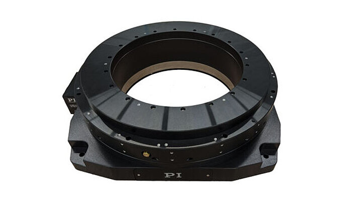
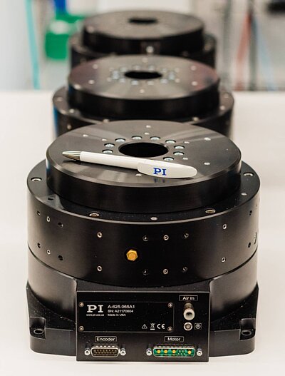
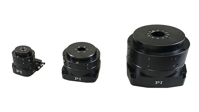
PI’s direct-drive rotary tables with frictionless, brushless, closed-loop torque motors provide the best combination of high accuracy, high velocity, and maximum service life. PI provides closed-loop direct drive rotary tables with both mechanical bearings and air bearings. Stage models with large apertures and low profile are available. The stage design is optimized for high speed, stiffness, and high load capacity. If completely friction-free and maintenance free motion with virtually unlimited lifetime is required, air bearing rotation tables are recommended. These ultra-precision, high-speed rotary tables provide vibration-free motion with extremely high accuracy and negligible runout, wobble and eccentricity errors. The lack of lubricants makes these also clean room compatible and ideal for any high-performance metrology application in optics, photonics, and semiconductor manufacturing, test and metrology related projects.
In contrast to worm gear driven rotary stages or belt-drive rotation stages, torque-motor direct drive stages eliminate play in gears, couplings or flex in drive belts, providing motion with zero backlash and excellent constancy of velocity, while achieving higher speed than worm-gear drives.
PI’s precision direct-drive, positioning tables can be used in high performance factory automation, research, semiconductor, and laser processing applications. Due to the use of brushless high-torque, motors with direct metrology position feedback, backlash is completely eliminated, and reliability is greatly improved.
With modern direct-metrology rotary encoders, sensor resolution down to 1/100th of a microrad is available on select models with large rotary table platforms, using the high interpolation factors
Based on the high encoder resolution and powerful servo controllers, the direct-drive rotary tables also provide excellent velocity control, which is required in automation applications including high-speed laser processing, indexing, and semiconductor wafer inspection.
Most Direct Drive Rotation stages can be mounted horizontally and vertically, and with combinations all 3 rotary degrees of freedom (3DOF, pitch, yaw, and roll) can be addressed.
Our direct drive rotary tables provide high torque and are easy to integrate. They contain high-energy magnets in a simplified mechanical design and drive loads directly without the need for a transmission mechanism or gearbox. It allows customers to build them right into a drive system for flexible placement and integration with cooling pipes and cables, for example.
We supply a wide range of frameless motors, and our adjustable motors include an optical encoder, scale, bearing and housing. Given our selection, it can be challenging to choose the best direct drive motor for your project. Our engineers prefer to help you find the right rotary table for your requirements.
Our most popular rotary motor, the AXD series is characterized by a slim, compact "pancake" design with high peak and continuous torque despite the motor"s quite small form factor.Direct drive and brushless motor
The ACD series is a set of ironless rotary tables. This motor is cogging-free and features high-resolution optical encoder feedback and low speed variability. This permanent magnet motor is equally suited for either low or high speed applications.Zero cogging coreless motor
The ACW series features a cogless construction and lean design, with high-precision coding and ultra-precision bearings. Together, this results in our highest performing motor in terms of repeatability and smooth motion.Direct drive brushless motor
The ADR-A series is available with both low and high speed windings and is fully equipped with an encoder and bearing. This series has a high slot fill factor and generates very high torque.Direct drive brushless permanent magnet motor

The HR-3 high speed rotary table is the ideal product for spinning light weight components at fast speeds. Possible applications include accelerometer and gyro calibration.
The HR-3 uses a high torque direct drive stepper motor. This design eliminates the use of worm gears which gives the HR-3 fast speeds, high reliability, and maintenance free operation.
Our product range includes single and multiple axes, tilt/rotating tables, and indexing and high-speed spindles. Additionally, we offer customized solution tables for customer requests or OEM projects.
Customer satisfaction is our highest priority. Due to a high degree of vertical integration, our customers have one point-of-contact and the guarantee that all components are manufactured and assembled to your specifications.
Even for EDM machines that have been in use for decades, we will work with you to determine the ideal rotary indexing table and/or rotating/indexing spindle solution.
Our state-of-the-art rotary indexing tables and customizable reference and clamping systems provide endless application possibilities and highly efficient solutions.
Among the many indexer manufacturers, what sets Pascal’s indexing table apart is undoubtedly its brakeless design, compact size, and durability. It has an ample amount of ports lending itself well to automation.
Pascal’s MDF index table operates with a 90° index 0.5 sec. Its unique rolling gear transmission is maintenance free and can operate with high index speed and accuracy for a long time unlike traditional worm gear. Traditional worm gear undergoes abrasive wear that can lead to backlash causing machining failure and degrading index accuracy.
Pascal’s high-performance rotary unions are integrated to enable clamp sensing and actuation but also provides a footprint 20% smaller than its competitors. Ideal for indexing large workpieces in compact machining centers, you will also achieve increased production capacity. As one example, our rotary indexing table can allow a machining center to increase their production capacity from 16 robodrill units to 24 units in the same amount of space.
The MDF index table has a total of 20 ports, lending itself well to automation. 18 of those ports can be used for hydraulic and air, while 2 are for coolant. A double acting cylinder with sensing can be used instead of a single cylinder, and its rotary joint accommodates a 7MPa pressure circuit.
Pascal is confident in the quality and reliability of our rotary indexers so much so that we use them in our own factories. That is also why these indexers are utilized in the factories of major automakers around the world.

In vertical movements, the engine must overcome gravity and additionally provide a force for vertical upward movement (F = mg + ma). In this case, the maximum load is determined by the maximum force divided by 9.81 m/s ². If the vertical force needs to be continuously maintained, the maximum load is the continuous power of the engine. For example, the maximum vertical load of the AUM2-S2 engine is 2.2 kg, since the continuous force of this engine is 22 N. If the load is borne by a counterweight (such as a spring), the AUM2-S2 engine can move a higher load in a vertical position.
There is no theoretical limit to the speed of a linear engine because there is no contact. However, speed is typically limited by the mechanical bearings. For example, the maximum speed for linear control systems with rails and guide cars is usually limited to 5m/s. Therefore, the speed for linear motors in most applications is limited to 5m/s. The use of ceramic ball bearings allows speeds of up to 10m/s. By using air bearings, higher speeds can also be possible.
Linear Motors can be used in cleanroom environments. In fact, many front-end semiconductor applications have linear motors in use. In wafer manufacturing plants, high-precision lithography machines, for example, use linear motors in XY positioning tables with very high accuracy (nanometer resolution) and submicron accuracy in cleanroom classes according to ISO 2.

In vertical movements, the engine must overcome gravity and additionally provide a force for vertical upward movement (F = mg + ma). In this case, the maximum load is determined by the maximum force divided by 9.81 m/s ². If the vertical force needs to be continuously maintained, the maximum load is the continuous power of the engine. For example, the maximum vertical load of the AUM2-S2 engine is 2.2 kg, since the continuous force of this engine is 22 N. If the load is borne by a counterweight (such as a spring), the AUM2-S2 engine can move a higher load in a vertical position.
There is no theoretical limit to the speed of a linear engine, because there is no contact. However, speed is typically limited by the mechanical bearings. For example, the maximum speed for linear control systems with rails and guide cars is usually limited to 5m/s. Therefore, the speed for linear motors in most applications is limited to 5m/s. The use of ceramic ball bearings allows speeds of up to 10m/s. By using air bearings, higher speeds can also be possible.
Linear Motors can be used in cleanroom environments. In fact, many front-end semiconductor applications have linear motors in use. In wafer manufacturing plants, high-precision lithography machines, for example, use linear motors in XY positioning tables with very high accuracy (nanometer resolution) and submicron accuracy in cleanroom classes according to ISO 2.
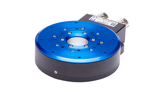
This compact closed-loop direct drive rotary table uses a 3-phase motor for maintenance free, frictionless power transmission. It comes in two variations, standard and with holding brake.
Application video of the silent ultrasonic piezo motor rotary stage in a Leica Theodolite and Principle Design of the PILine drive used in the M-660 PILine� rotary stage
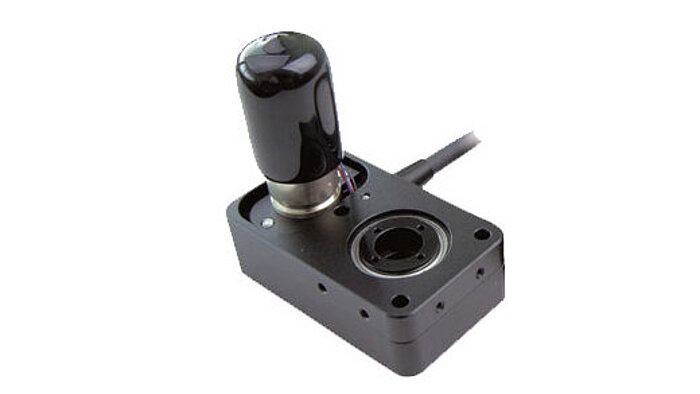
This miniaturized closed-loop rotary positioner is driven by an ultrasonic direct-drive motor and provides high rotational velocity up to 3 revolutions / second. An optical encoder is integrated for direct position measurement and feedback with 35 �rad resolution.
A fast ultrasonic ceramic ring-shaped resonator motor provides high speed to 120 RPM. An optical direct metrology encoder is integrated for position feedback.
Q-motion series miniature rotation stages are driven by inertia-type piezo motors. These miniaturized positoining tables are direct-driven, backlash free and provide micro-radian resolution. The self-locking design requires no holding current and provides excellent long-term stability. Three different diameters are available: 14 mm, 22 mm and 32 mm.
PI"s air-bearing rotation stages provide the highest accuracy and smoothest motion of any commercially available rotation stage. With standard and custom designs these stages are designed for reference class applications.
The PI miCos line of goniometers and rotation stages is specialized on miniature stages with different motor drives (belt-drives, worm-gear drives) and also on ultra-high precision stages with torque motors, direct metrology and air bearings.
P-5x8 series, Z/tip/tilt nanopositioners are open-frame, high-resolution, piezo-driven stages providing Z motion to 240 �m and rotation around X and Y to 2.4 mrad with resolutions of up to 0.5 nm and 50 nrad. The 66 x 66 mm clear aperture is ideal for transmitted-light applications.
Goniometric cradles are used to rotate samples and objects to a precise angular position. The units here are equipped with precision servo and stepper motors and high-resolution encoders for angular position feedback.

The present invention relates to an apparatus and a method for determining a position of a repeat stop origin of a disk rotating at high speed in a short time and with high accuracy. In particular, it automatically performs subtle operations from outside the disk, such as injecting, processing, and discharging samples into containers existing on the disk, or attaching, processing, and removing members to and from the disk, without using human hands. About making things possible.
In order to stop the disk rotating at high speed and automatically perform the above-mentioned delicate operation from the outside, the operation target position in the disk shape is always constant, that is, the disk always stops at the same position. Is assumed. For this purpose, it is necessary to accurately determine the position of the origin at which the disk is repeatedly stopped, and it is important to perform positioning in a short time from the viewpoint of working efficiency and the like. Various studies have been made to satisfy these requirements, but at present it is difficult to achieve this in the case of a high-speed rotating disk.
First, with a high-speed rotating disk, it is difficult for a normal high-frequency motor to adjust the rotating speed over a wide range at high speed and at low speed. That is, when the rotation speed is less than 100 rpm, it is difficult to control the rotation speed, and therefore, it is not possible to determine the repeat stop origin position accurately and in a short time.
Therefore, when repeated stop positioning is required, a servomotor is often used. The servomotor has a mechanism of detection by an encoder, control by a microcomputer, and the like, and can be controlled even in a relatively low speed range.
However, the servo motor does not sufficiently support high-speed rotation, and the limit is about 5,000 rpm. In addition, the positioning accuracy is not sufficient. For example, in the case of a disk having a diameter of 300 mm, if one rotation is counted as one thousand pulses, an error of about ± 1 mm is inevitable in the circumferential portion. Furthermore, when a force is applied from the outside, the servomotor tends to fluctuate even with a small torque, and it is difficult to fix the position accurately. That is, when the disk is stopped, there is slight vibration, and when the outer diameter of the disk becomes large, the outer periphery may move several mm due to external force. Furthermore, the motor, the control driver, the rotary encoder, the high-speed counter, the microcomputer, and other mechanisms are large-scale, and it is difficult to increase the apparatus cost.
A stepping motor may be used as the motor. However, the stepping motor has a rotation speed limit of about 1,000 rpm, and is essentially unsuitable for high-speed rotation. Unlike a servomotor, a rotary encoder for feedback function and rotation detection is omitted at the expense of controllability, but the apparatus cost is still high.
Patent Literature 1 relates to positioning of a rotor in an automatic centrifuge, and differs from the object of the present invention, but is an example using a stepping motor. Although the positioning is performed at a reduced rotational speed, the method of Patent Document 1 cannot repeatedly and accurately determine the stop origin position in a short time.
Further, Patent Document 2 relates to a method for indexing a turret lathe with a rotary tool, which is also an example using a servomotor, although the purpose and apparatus are different from those of the present invention. This example has the disadvantages of the servomotor described above. On the other hand, since the positioning pin is used at the time of positioning, the position is fixed. However, in the example of Patent Document 2, the pin is engaged and the rotating operation is continued. The purpose of the present invention is completely different from that of the present invention.
As described above, in the conventional technique, it is difficult to repeatedly perform the positioning of the stop origin on the high-speed rotating disk with high accuracy and in a short time. In particular, it cannot be applied at all to the positioning of a turntable used at a maximum rotation speed of 8,000 to 20,000 rpm.
2. Description of the Related Art In recent years, microreactor chips for performing a predetermined chemical reaction or treatment using a small amount of a liquid substance such as a sample or a specimen and used for analysis and inspection in the biochemical field and the like have been developed. The analysis or inspection is performed by a high-speed rotating disk device provided with an external operating mechanism for attaching, discharging, or analyzing the liquid by attaching the chip having the liquid holding portion to the high-speed rotating disk. That is, when the high-speed turntable is stopped, a sample or a sample is injected, high-speed rotation is performed, reactions and processes are performed while the sample or the like flows through the liquid flow path in the chip, and analysis and discharge are performed after the rotation is stopped. .
The present inventor further studied the high-speed rotating disk device used in the biochemical field and the like, that is, the centrifugal force-based liquid layer reaction device, and as a result, the chip having the above-described liquid holding unit was rotated together with the high-speed rotating disk. A sheet-like structure having a liquid holding portion and a void forming a liquid flow path, wherein the direction of the sheet-like structure with respect to the high-speed rotation center axis is variable, and the direction is fixed during high-speed rotation. In the case of a device having a mechanism, it was found that the device had a remarkable effect and utility, and a patent application was filed earlier (January 20, 2003).
In these biochemical analyzers and the like, high-speed rotation is performed by centrifugal force to move the liquid in the circumferential direction from the center of rotation to move a narrow flow path on the chip. In addition, miniaturization and precision are progressing.To automate operations such as injection, processing, analysis, and discharge of a sample from the outside to the chip on the board without manual operation, it is necessary to operate It is necessary that the chips on the board are always in a precise and fixed position. That is, it is necessary to perform the repeat stop origin positioning more accurately than in the past. In addition, performing positioning in a short time is an important requirement not only for work efficiency but also for controlling the reaction and the processing time.
SUMMARY OF THE INVENTION An object of the present invention is to solve the above-described drawbacks of the conventional high-speed rotating disk device and to enable delicate automation from outside. In particular, it aims at automation in a device using a microreactor in the field of biochemistry and the like.
As a result of intensive studies to achieve the above object, the inventor of the present invention has found that a high-speed rotary disk having a V-shaped groove on the outer periphery, a high-speed rotary shaft roll rotating simultaneously with the high-speed rotary shaft, and a high-speed rotary drive of the high-speed rotary disk. High-speed motor, dock section that serves as a mark for detecting the origin position of the high-speed turntable with a sensor, position detection sensor that detects the position near the origin of the high-speed turntable, position detection sensor that detects the origin position of the high-speed turntable, high-speed rotation A low-speed roll that rotates the board at low speed, a low-speed motor that drives the low-speed roll to rotate, a brake that stops the low-speed motor instantaneously, a low-speed roll part moving mechanism that makes the low-speed roll contact or non-contact with the high-speed rotary shaft roll, a high-speed rotary disk The above-mentioned difficulties are caused by a high-speed rotating disk device equipped with a pin stopper having a shape that bites into the V-shaped groove of the above and a pin moving mechanism that makes the pin stopper bite or not bite. It has been found that can solve.
That is, 1) a position detection mechanism including a dock portion and a position detection sensor in the high-speed rotating disk, 2) a high-speed rotating shaft roll and a low-speed roll driven independently of each other, and 3) a pin stopper that cuts into a V-shaped groove of the high-speed rotating disk. By combining these three elements, the positioning of the stop origin repeatedly was successfully performed in a short time and with high accuracy. In addition, it is possible to achieve the purpose by using a low-cost drive system such as an inverter-driven high-frequency motor instead of an expensive servo motor or a stepping motor as a drive motor.
An origin position detecting mechanism including a dock portion and a sensor is known. However, as in the present invention, no example has been found in which high-speed rotating disks succeed in performing origin positioning in a short time, with high accuracy, and at low cost. That is, an unexpectedly large effect is obtained only by an exquisite combination with the above-mentioned other requirements including the dock portion, the near-origin position sensor and the origin position sensor.
It is known that the rotation speed is reduced from the high-speed rotation to the low-speed rotation to perform the origin positioning operation. However, if the same roll, that is, the high-speed rotating shaft roll, is used, it is difficult to adjust the rotation speed in the low-speed region as described above, and it is not possible to determine the stop origin position repeatedly accurately and in a short time. The objective is only achieved by switching to independently driven low speed rolls and satisfying other requirements.
It is conceivable for a person skilled in the art to fix the rotating object by making the pin stopper bite into the V-shaped groove of the rotating object. However, it is not known at all that in the high-speed rotating disk aimed at by the present invention, the stop origin position can be repeatedly determined with high accuracy. By satisfying the requirements of the present invention, it has become practically applicable for the first time in a high-speed rotating disk. For example, as described above, in the case of a servo motor, in the case of a disk having a diameter of 300 mm, if one rotation is counted as 1,000 pulses, an error of about ± 1 mm is inevitable in the circumferential portion. In this case, about ± 0.01 mm, which is about 100 times.
The present invention does not use an expensive drive system. The high-speed motor for high-speed rotation can be an inverter-driven high-frequency motor, and the low-speed motor for driving the low-speed roll can be an AC motor with gears.
First, when the stop origin position is repeatedly determined for the first time before an operation is externally applied to the high-speed rotating disk, the following is performed. That is, in a state where the high-speed rotating disk is stopped, it is confirmed that the low-speed roll is not in contact with the high-speed rotary shaft roll, and the pin stopper is disengaged from the V-shaped groove. Then, the low-speed motor is brought into contact with the high-speed rotating shaft roll to start the low-speed rotation of the high-speed rotating plate, then the near-origin position detection sensor detects the dock, transmits a near-origin signal, and then decelerates with the low-speed motor. Control lowers the low-speed roll and high-speed rotating shaft roll, then the origin position detection sensor detects the dock and sends out the origin signal, then the brake is activated, and the low-speed roll, high-speed rotating shaft roll and high-speed rotating The board is stopped, and then the pin stopper is cut into the V-shaped groove.
When the rotation of the target high-speed turntable is repeatedly performed and the stop origin position is repeatedly determined when the rotation is stopped, the following operation is continuously and automatically performed. That is, at the determined repetition stop origin position, in a rotation stop state after externally applying an operation to the high-speed turntable, the low-speed roll is not in contact with the high-speed rotary shaft roll, and the pin stopper is moved from the V-shaped groove. Remove, then rotate the high-speed rotating disk with a high-speed motor, then decelerate the high-speed motor with a stop signal from a timer, etc., then remove the low-speed motor brake to start rotation, and then When the rotation speed becomes lower than a certain value, the high-speed motor is released, the low-speed roll is brought into contact with the high-speed roll, and the high-speed turntable is rotated only by the low-speed roll. Detects and sends a signal before the origin, then decelerates the low-speed roll and high-speed rotating shaft roll by deceleration control by a low-speed motor, and then returns to the origin position The output sensor detects the dock and sends out the origin signal, then the brake is operated to stop the low-speed roll, high-speed rotating shaft roll and high-speed rotating plate, and then the pin stopper bites into the V-shaped groove. I do.
FIG. 1 is a side view of a model of a high-speed turntable device according to an embodiment of the present invention, and FIG. 2 is a plan view of the model.
The high-speed turntable device 1 includes a high-speed turntable 2, a rotation drive mechanism, a position detection mechanism, and a stopper mechanism, and an external operation mechanism 16 is additionally provided.
On the high-speed turntable 2, chips 15a, 15b, 15c, and 15d having a liquid holding portion and rotating with the high-speed turntable 2 are provided. The number of chips is four in this embodiment, but may be an appropriate number depending on the situation.
The high-speed rotating disk 2 is rotated by a high-speed rotating shaft roll 3. The high-speed rotating shaft roll 3 is driven by a high-speed drive motor 4. At the time of low-speed rotation, the high-speed drive motor 4 is separated from the high-speed rotation shaft roll 3 to be free, and instead, the low-speed rotation roll 8 is brought into contact with the high-speed rotation shaft roll 3 and rotated. The low-speed rotating roll 8 is provided with a low-speed motor 9 and a brake 10. The low-speed roll unit moving mechanism 11 contacts and separates the low-speed rotation roll 8 from the high-speed rotation shaft roll 3.
The position detection of the high-speed turntable 2 is performed by a position detection mechanism including an origin position detection sensor 6, an origin position detection sensor 7 and a dock unit 5. Conventional methods and mechanisms such as optical detection can be used. The dock portion 5 may be a protruding portion or a cutout portion.
The high-speed turntable 2 has a V-shaped groove 14, into which a pin stopper 12 with a cushion spring is engaged, thereby fixing the rotation stop position. The pin stopper 12 is moved and controlled by a pin removing mechanism 13. By applying pressure by using a cushion spring and making the pin stopper 12 bite into the V-shaped groove 14, the pin stopper 12 can be firmly fixed.
The high-speed turntable 2 is provided with an external operation mechanism 16. Since repeat stop origin positioning can be performed accurately and in a short time, various operations from the outside can be performed automatically and efficiently.
FIG. 3 is a model plan view showing the relationship between the position detection sensor and the pin stopper in the rotation process of the high-speed rotating disk of FIG.
FIG. 3A is a model plan view in a normal rotation state. The origin position sensor 6 is OFF, the origin position near side sensor 7 is OFF, the pin stopper return sensor 18 is ON, and the pin stopper biting sensor 19 is OFF. The pin stopper 12 is located away from the high-speed turntable 2 and returned.
According to the present invention, it is possible to determine the repeat stop origin position with high accuracy and in a short time in the high-speed rotating disk device. In this case, a low-cost high-frequency motor or the like can be used as the drive motor without using an expensive servo motor or the like. In addition, since the stop origin position can be repeatedly determined with high precision, various operations on the containers and members on the high-speed rotating plate can be automated without human intervention. In addition, since the determination can be made in a short time, the operation can be performed efficiently and the operation is restricted.
In particular, in the field of biochemistry and the like, it becomes possible to mount a microreactor chip on a high-speed rotating disk and perform analysis and inspection automatically.
1 is a side view of a model of a high-speed rotating disk device according to an embodiment of the present invention; FIG. 2 is a plan view of a model of the device of FIG. 1; FIG. (A) Model plan view in the middle of normal rotation (B) Model plan view in the state where only the sensor near the home position is on (C) The home position sensor is also on , Model plan view with rotation stopped [Explanation of symbols]
DESCRIPTION OF SYMBOLS 1 High-speed rotating disk device 2 High-speed rotating disk 3 High-speed rotating shaft roll 4 High-speed drive motor 5 Dock 6 Origin position detection sensor 7 Origin position detection sensor 8 Low-speed rotating roll 9 Low-speed motor 10 Low-speed motor brake 11 Low-speed roll part moving mechanism 12 Pin stopper 13 Pin stopper removal mechanism 14 V-shaped grooves 15a, 15b, 15c, 15d
Tip 16 having liquid holding part 16 External operation mechanism 17 Pin stopper slide 18 Pin stopper return sensor 19 Pin stopper biting sensor 20 Rotation direction of high speed turntable

In 1996, Precision Detroit Company established a relationship with WEISS GmbH. WEISS has been manufacturing high quality index tables for decades and is the leading automation component manufacturer in Europe today.
In August, 2007, WEISS GmbH established WEISS North America, Inc. as a wholly-owned subsidiary. On September 30, 2007, WEISS North America, Inc. acquired the assets of Precision Detroit Company, Inc. relative to its PDC Geneva Motion index tables and its network of sales representatives throughout the U.S. and Canada.
Today, WEISS North America is not only a rotary table manufacturer but your complete automation manufacturer and solutions partner. WEISS has decades of expertise in providing automation, drive and control solutions to industrial markets. WEISS offers industry-specific, cost-effective and efficient technology solutions to help you maximize your efficiency, increase your productivity and achieve optimal system performance. We understand that your application has unique processes and specific requirements and we work closely with you to develop the perfect automation solution for your particular needs.


 8613371530291