
nikken rotary table maintenance manual quotation

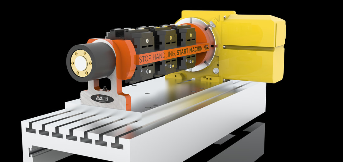
Martin Trunnion Tables and Lyndex Nikken are now offering complete 4th axis packages. Ready to be mounted into your machine tool, your Stallion Trunnion Table will already be attached to the Lyndex Nikken rotary table of your choice and assembled onto a baseplate. This allows for an easy transition from 3-axis machining to 4-axis machining. Our line of trunnion tables can be made to fit any Lyndex Nikken indexer. Multiple workholding options are also available including 5th axis, AME, Schunk, Triag, Orange Vise and more. If you have any questions, do not hesitate to reach out to one of our applications engineers! Scroll down to view package options.
Are you looking for an accessory to boost the precision of your modern machining centers? CNC rotary tables provide a versatile tool in expanding the capabilities of your machines. They allow for precision positioning during 4 and even 5 axis cutting operations, thereby transforming 3-axis machinery into CNC machines with heightened accuracy. CNC rotary tables are a cost-effective solution to perform complicated machining tasks, with additional benefits such as increased productivity, efficient use of labor and materials, and better quality control.
Additionally, CNC rotary tables can be used independently to mount other components on a table, including trim attachments and chucks for drilling applications. CNC rotary tables offer considerable advantages that promote their usefulness in a variety of industrial settings.
Looking to sell your CNC Rotary Table? Simply fill out the sell your machine form and we will get back to you with a quote. Interested in one of our used machines for sale? Simply click the “Get Quote” button and a sales representative will contact you shortly.
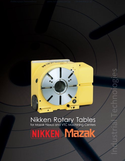
Pioneers in the industry, we offer Nikken NSVX400 Rotary Hirth Indexer, Nikken NSVX500 Rotary Hirth Indexer, Nikken NSVZ300 Rotary Hirth Indexer, Nikken NSVZ180 Rotary Hirth Indexer, Nikken Cncb630 Ultra Big Bore Rotary Table and Nikken DD400F-250 Direct Drive Rotary Table from India.
![]()
Eagle Machine, Inc. is a distributor for Eurotech Multi Tasking Lathes, Hermle Precision 5 Axis Machines, Fermat Horizontal Boring Mills, YCM Precision Machines, Cosen Saws, NIKKEN Tooling & Rotary Units, Golden Sun rotary tables, Sharp Manual Machines
2. To drain the A axis unscrew the drain port [4] at the bottom of the rotary. The rotary likely will be to be suspended in the air to do this. Rotary units are heavy so take appropriate safety measures while draining the oil. Clean off the oil remaining on the rotary and replace the screw. Both rotaries have two screws on the bottom.
4. To drain the B axis tilt axis to 90° and unscrew the drain port [3]. Only one side has a drain port check for it before tilting the rotary. Once the rotary is empty screw the port plug back in.
A large number of specially selected, high-quality second user products are available through our webshop or directly from our technical sales department, providing rotary table products that have been fully rebuilt exclusively by us, to a very high...https://facebook.com/cncrotaryshop/videos/475171379666589/…

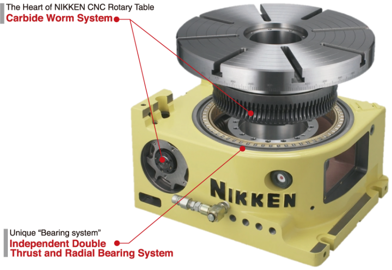
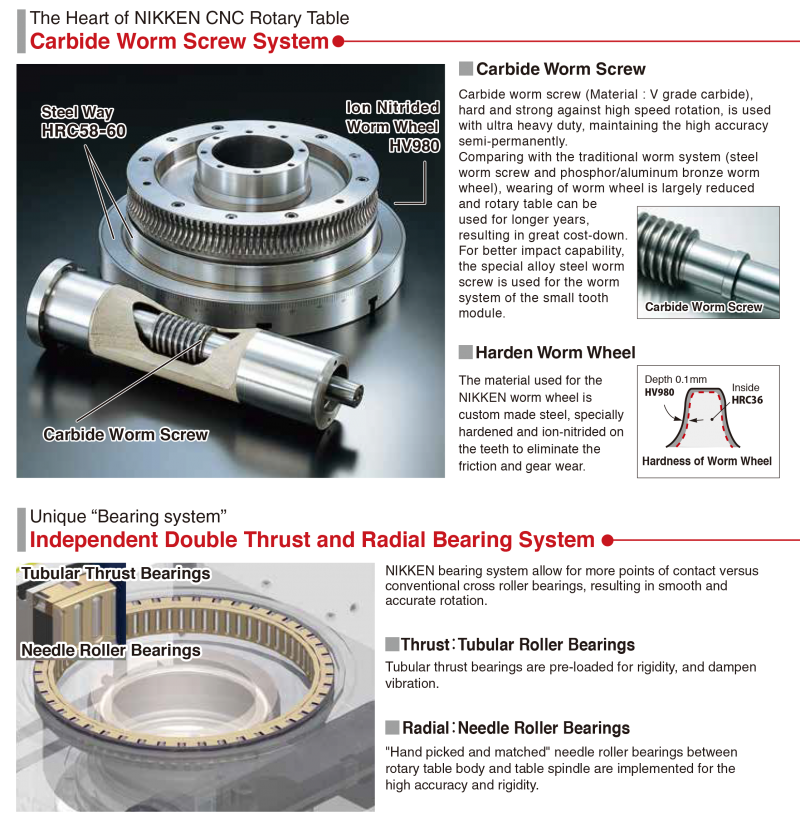
2 CNC ROTARY TABLE CNC ROTARY TABLE for Full Automation Ion Nitrided Worm Wheel HV980 Steel Way HRC58 Carbide Worm Screw Photo shows the worm system of CNC401. Work Sample Please see for more work samples. P.37 and P.46 Multi-setting on multi-planes P. 44 1
3 Carbide Worm Screw CARBIDE WORM SYSTEM Anti-Wearing, High Rigidity and High Speed Rotation Carbide Worm Screw, hard and strong against high speed rotation, is used. (Photo at right hand side)[material : V grade Carbide: High anti-wearing and tough quality] Ultra heavy duty, maintaining the high accuracy semi-permanently. Comparing with the traditional combination of worm system (phosphor bronze, aluminium bronze worm wheel and steel worm screw), wearing is largely reduced and table is usable for much more years, resulting in great cost-down. For better impact capability, the special alloy steel worm screw is used for the worm system of the small tooth module. Worm Wheel Material is special NIKKEN order made steel. Specially hardened and furthermore ion-nitrided on the tooth. Thus, the problem of the sliding friction is solved. The hardness of the tooth surface and inside is shown at right hand side. Depth 0.1mm HV980 Fig. 2 Inside HRC36 Hardness of Worm Wheel (micron) Backlash(Amount of wearing) Backlash Compensation 3mon. 6mon. 12mon. 2yrs. 3yrs. Useful Life Fig.1 Phosphor Bronze /Aluminium Bronze Worm Gear (22.2min -1 ) NIKKEN CNC Rotary Table CNCZ 2 (66.6min -1 ) Rotation speed of motor = 3,000min -1 Dynamic High Pressure Oil Film Effect for High Speed CNC Rotary Table Z Series NIKKEN"S experience in gear cutting and study of the pressure angle of worm screw carry out the table"s higher rotation speed (66.6min -1 ). The rotational speed of the screw creates the pressure to force the oil between the gears preventing any metal-to-metal contact, eliminating gear wear and producing high rigidity and durability. Large size rotary tables are made a lineup The large size rotary tables for the large size machine tool, the large size die mould, energy and air craft are made a lineup. P.11, P.29 The NIKKEN carbide worm system is installed in the rotary table with the super durability, accuracy and rigidity. Dynamic High Pressure Oil Film CNC11 5AX-10 CNC10 CNC0 Turbine Blade High Speed CNC Rotary Table Z series for high speed milling marked arrow. 2
4 INDEX CNC105,0,2 COMPACT CNC ROTARY TABLE P. 56 COMPACT ROTARY TABLE with 21 CONTROLLER P. 69 CNC100-2W,3W,4W,CNC0-2W,CNC2-2W,CNC2-2W MULTI-SPINDLE CNC ROTARY TABLE P. 19 CNC2,302,321,401,501,1,803,1003,B350,B450,802 CNC ROTARY TABLE P. 710 CNC ROTARY TABLE with 21 CONTROLLER P CNC1000, 10, 11, 10, 00 LARGE CNC ROTARY TABLE P LARGE ROTARY TABLE with 21 CONTROLLER P. 70 CNC0B,2B,2B,302B,321B,401B BACK SIDE MOTOR MOUNTED CNC ROTARY TABLE P CNC0T, 2T, 302T, 321T, 401T, 501T, 1T TOP SIDE MOTOR MOUNTED CNC ROTARY TABLE P. 5AX-130, 1, 230,, 350, 550, 800, 10 TILTING ROTARY TABLE P TILTING ROTARY TABLE with 21 CONTROLLER P AX-2MT, 4MT MULTI-SPINDLE TILTING ROTARY TABLE P NST,300,500 MANUAL TILTING ROTARY TABLE P CNC503H 5AX-T400 NSVZ0, 300 NSVX400, 500 Indexing Accuracy (±2 ) ULTRA PRECISION ROTARY HIRTH COUPLING INDEX P NSVZ: Min. Command Incremental = 1 NSVX: Min. Command Incremental = 1, BUILT-IN TYPE CNC ROTGARY TABLE CNC401H, CNC503H P. 35 5AX-T400, -B450 P. 36 This is a CNC rotary table specially designed to be built into the machines. CNC Rotary Table for BROTHER T/C & P CNC Rotary Table for FANUC ROBO DRILLP. 42, P.44 3 DD, 400, 500, 5AX-DD0 Tilting Rotary Table with DD Motor for FANUC ROBO DRILL P. 4345
5 Optional Specification, Accessories & Technical Information Ample Accessories are available for NIKKEN CNC Rotary Table. For the additional or special specification, please fill in the specification mark sheet, and attach to your order. For the rotary tables marketing in EU, please order specifying "With CE Mark". All rotary tables are available with CE Mark. Optional Accessories AWC SYSTEM P.4748 Automatic Work Change system Series Attachment P.46 SCROLL CHUCK & POWER CHUCK P.49 TAILSTOCK P.50 Air/Air Booster & Air/Hydraulic Booster P.55 Air to Air and Air to Hydraulic Intensified Booster Hydraulic Unit P.46 Fitting Metals and Stepped Guide Pieces P.22 Special Specifications Servo Motor List P.37 Accuracy Standard P.52 Accuracy and measuring method Ultra Precision P.53 Rotary Joint P.54 Rotary connection for pneumatic/hydraulic fixture/chuck Built-in Pallet Clamp System P.55 Suitable for automatic pallet changer Water Proof Specification P.55 Available for waterproof connector and cable Special Application P.5758 World wide example and application Assessment of CNC ROTARY TABLE P.56 Technical Information of CNC ROTARY TABLE P.59 Load calculation, Indexing time, Durability and Instruction Indexing of the turbine shaft NIKKEN is keeping the manufacturing not only the quality, but also the safety in mind. Please be careful for the content maked. e.g. P. Nikken Controller 21 Controller P.6162 Technical Information for 21 Controller P.6368 Termination of the maintenance work for NIKKEN controllers CNC Rotary Table with 21 Controller P.6972 Selection of the CNC ROTARY TABLE P.73 NIKKEN EUROPE (UK) LYNDEX-NIKKEN (U.S.A.) Nikken Worldwide Network HEAD OFFICE & FACILITY P.7476 OVERSEAS SALES & SERVICE NETWORK P.77 NIKKEN CHINA (CHINA) P.78 LYNDEX-NIKKEN (USA) P.79 NIKKEN EUROPE (UK) P.80 NIKKEN DEUTSCHLAND (GERMANY) P.81 PROCOMO-NIKKEN (FRANCE) P.82 4
6 Item / Code No. Diameter of Table φmm Diameter of Spindle Hole φmm Centre Height mm Width of T Slot mm Clamping System Clamping Torque Nm GD Table Inertia at Motor Shaft 2 4 m Servo Motor min -1 MIN. Increment Rotation Speed min -1 Total Reduction Ratio Indexing Accuracy sec Net Weight Vertical Work Load on the Table COMPACT CNC ROTARY TABLE CNC105 Specifications Horizontal 21 and attachments CNC105 CNCZ φh7 φ φ10h7 Pin hole Air if1/ (44.4) 1/90(1/45) ±30 32 Wide application can be offered from small Drilling Press to M/C. Suitable for indexing/leads cutting of small size work pieces. Various kinds of the work chucking attachments can be offered from 5C collet fixtures to the air/hyd. chuck. P. 46 Explanation of the Code No. (Example) CNC 105 L F A - M ( ):High Speed CNC ROTARY Table Z series No Letter: without motor M: with Motor No Letter: DC servo motor A: AC servo motor Motor Maker P. 37 A21: with NIKKEN 21 controller F:FANUC M:MELDAS Y:YASNAC OSP:OSP T:TOSNUC N:NEC S:SANYO Z:SIEMENS I:INDRAMAT H:HEIDENHAIN X:ISOFLEX SEM:SEM B:BOSCH No letter: Right hand mounted motor L: Left hand mounted motor Diameter of Table 105, 0, 0 CNC: Standard CNCZ: High Speed Z series CNC0 CNCZ0 0 φh7 φ Air if2/ (44.4) 1/90(1/45) ± 45 CNC2L Rotary table with 21 controller, refer P.69 CNC2 CNCZ2 0 φh7 φ Air if4/ (44.4) 1/90(1/45) ± 55 5 Thrust Load applicable on the Table Guide Line of Unbalancing Load Work Inertia Driving Torque 1 2 Vertical 3 GD 2 4 N FL Nm FL Nm m m 2 Nm 1 This is the strength of the worm wheel without brake. It is applied against dynamic cutting thrust. 2 The guide line of MAX unbalancing load means the unbalancing load, when the rotary table is used with support table in vertical application. The guide line figure will be different according to the servo motor, please refer P.37 for more detail. 3 Driving torque means the torque at rotation speed after acceleration. Driving torque is almost constant and independent from the load except unbalancing load is applied. L type (Motor is mounted at left hand side) is available for all rotary tables. if4/5000 motor can be mounted on CNC0. AWC system is available for all rotary tables, please refer P.47P.48. Ultra precision type is available for all rotary tables, ±3 or ±5, please refer P.53. Rotary joint is available for all rotary tables, please refer P.54.
7 CNC105,0,2 CNC105, CNCZ105 External dimensions will be different according to the type of the servo motors. Dimensions with FANUC motor or with NIKKEN 21 controller ( 21 : ) are shown. Please contact with us for CAD data (2D:DXF, 3D:PARASOLID) ( 21:313) 252( 21:2) Powerful Brake Brake Torque : 5Nm φ φ 40 φ30 Photo shows a rotary table with 0 21 controller ( 21:128) Air purge function is provided inside the motor cover as standard. CNC0, CNCZ ( 21:326) 106 3( 21:2) Powerful Brake Brake Torque : 303Nm φ φ 55 φ40 Photo shows a rotary table with controller :130 Air purge function is provided inside the motor cover as standard. CNC2, CNCZ ( 21:346) ( 21:240) Powerful Brake Brake Torque : 303Nm φ φ φ ( 210) Photo shows a rotary table with 21 controller. Air purge function is provided inside the motor cover as standard. For accuracy standard, refer P.51, 52 For scroll chuck, tailstock and other optional accessories, refer P.49,50 For fitting metal and stepped guide piece, refer P.22 series attachment can be attached for all tables, refer P. 46 Counter Balance Cylinder Counter Balance Cylinder is standardized to solve un-balancing load. JAPAN. PAT Counter Balance Cylinder CNC0A Un-balancing Load Photo and illustration show the example of the application for un-balancing load. Small Size Support Table TAT(JAPAN. PAT) E A (105 2 ) 5 CST , 135 (w/o brake) TAT105 D C B Pneumatic ports are 2 x Rc1/8. Solenoid valve and clamp/unclamp confirmation switches are not included. Please add - centre height at the end of Code No. for the support table with different centre height (B). e.g.tat Code No. TAT105 TAT170 A 5 5 B C D E Clamping System Air Air Brake Torque 5 5 Weight Air pressure is 0.5MPa. (Nm) () Double intensifying clamping mechanism is installed on TAT105 & TAT170. Rotary joint is available for all models, refer P.54 6
8 CNC ROTARY TABLE Specifications Item / Code No. Diameter of Table φmm Diameter of Spindle Hole φmm Centre Height mm Width of T Slot mm Clamping System Clamping Torque Nm Table Inertia at Motor Shaft GD 2 4 m Servo Motor min -1 MIN. Increment Rotation Speed min -1 Total Reduction Ratio Indexing Accuracy sec Net Weight Work Load on the Table Vertical Horizontal CNC2 CNC2 CNCZ2 2 φ80h Air/ 588 / if4/ (33.3) 1/1(1/) CNC302 CNCZ φ80h Air/ 588 / if4/ (33.3) 1/1(1/) The rotary table can be used vertically or horizontally depending on the application. Explanation of the Code No. (Example) CNC 2 L F A - M ( ):High Speed CNC ROTARY Table Z series No Letter: without motor M: with motor No Letter: DC servo motor A: AC servo motor Motor Maker P. 37 A21: with NIKKEN 21 controller F:FANUC M:MELDAS Y:YASNAC OSP:OSP T:TOSNUC N:NEC S:SANYO Z:SIEMENS I:INDRAMAT H:HEIDENHAIN X:ISOFLEX SEM:SEM B:BOSCH No Letter: Right hand mounted motor L: Left hand mounted motor Diameter of Table 2, 300, 3, 400 CNC: Standard CNCZ: High Speed Z Series CNCB: Big Bore Rotary table with 21 controller, refer P.69, P.70 CNC321 CNCZ321 3 φ105h if12/ (44.4) 1/90(1/45) CNC401 CNCZ φ105h if12/ (44.4) 1/90(1/45) CNCB φ4h if12/ / Thrust Load applicable on the Table 1 N FL Nm Guide Line of Unbalancing Load Work Inertia Driving Torque 2 Vertical 3 GD 2 4 FL Nm m m 2 Nm This is the strength of the worm wheel without brake. It is applied against dynamic cutting thrust. 2 The guide line of MAX unbalancing load means the unbalancing load, when the rotary table is used with support table in vertical application. The guide line figure will be different according to the servo motor, please refer P.37 for more detail. 3 Driving torque means the torque at rotation speed after acceleration. Driving torque is almost constant and independent from the load except unbalancing load is applied. L type (Motor is mounted at left hand side) is available for all rotary tables. AWC system is available for all rotary tables, please refer P.47P.48. Rotary joint is available for all rotary tables, please refer P.54. Ultra precision type is available for all rotary tables, ±3 or ±5, plea se refer P.53. Ultra heavy duty type is available for CNC321, 401. if8/4000 motor can be mounted on CNC2, 302. if22/4000 motor can be mounted on CNC321, 401. The supplied hydraulic pressure is 3.5MPa for hydraulic clamping system. The air-hydraulic booster is available, when the rotary table with hydraulic clamping system is used on the M/C without hydraulic source, please refer P
9 CNC2,302,321,401,B350 CNC2, CNCZ2 External dimensions will be different according to the type of the servo motors. Dimensions with FANUC motor or with NIKKEN 21 controller ( 21 : ) are shown. Please contact with us for CAD data (2D:DXF, 3D:PARASOLID) ( 21:452) 365( 21:295) 9 Pneumatic Brake Torque UP 588Nm 170 φ (21:0) 195 For the rotary table with pneumatic brake, air purge function is provided inside the motor cover as standard ( 21:452) 365( 21:295) 170 φ φ105 φ80 CNC302, CNCZ302 9 Pneumatic Brake Torque UP 588Nm φ105 φ80 CNC321, CNCZ IN port pitch ( 21:0) For the rotary table with pneumatic brake, air purge function is provided inside the motor cover as standard. Built-in type rotary joint can be mounted on CNC321 & 401, refer P OUT port φ φ130 φ105 CNC401, CNCZ Built-in type rotary joint can be mounted on CNC321 & 401, refer P OUT port IN port pitch φ φ130 φ Photo shows with rotary joint (option). CNCB350 Ultra Big Bore (φ4mm) Specification available as an option. 210 φ φ0 φ4 φ5 φ4 For accuracy standard, refer P.51, 52 For fitting metal and stepped guide piece, refer P For scroll chuck, tailstock and other optional accessories, refer P.49,50 For the condition of CNC table which is mounted on CNC special purpose machine, refer P.59, 8
10 CNC ROTARY TABLE Dividing and lead cutting for large size work piece is suitable. Large through hole and powerful clamping system. CNC1 Explanation of the Code No. (Example) CNC 1 F A - M No Letter: without motor M: with motor No Letter: DC servo motor A: AC servo motor Motor Maker P. 37 A21PW: with NIKKEN 21 controller F:FANUC M:MELDAS Y:YASNAC OSP:OSP T:TOSNUC N:NEC S:SANYO Z:SIEMENSI:INDRAMAT H:HEIDENHAIN X:ISOFLEX SEM:SEM B:BOSCH No Letter: Right hand mounted motor L: Left hand mounted motor Position of motor No Letter: Horizontal V: Vertical Diameter of Table 500, 0, 800, 10 CNC: Standard CNCZ: High Speed Z Series CNCB: Big Bore Specifications Diameter of Table φmm Diameter of Spindle Hole φmm Centre Height mm Width of T Slot mm Clamping System Clamping Torque Nm Table Inertia at Motor Shaft GD 2 4 m Servo Motor min -1 MIN. Increment Rotation Speed min -1 Total Reduction Ratio Indexing Accuracy sec Net Weight Work Load on the Table Item / Code No. Vertical Horizontal ( ):High Speed CNC ROTARY Table Z series CNC501 CNCZ φ130h if12 / (33.3) 1/ 1(1/ ) CNC1 CNCZ1 0 φ130h if12 / (22.2) 1/ 0(1/ 90) CNC CNCB CNC φ230h7 550 φ230h7 550 φ5h7 280 φ270h H74 22H H if30 / if30 / if12 / if22 / / Rotary table with CNC / / PW controller, refer P / Thrust Load applicable on the Table Guide Line of Unbalancing Load Work Inertia Driving Torque 1 2 Vertical 3 GD 2 4 N F L Nm F L Nm m m 2 Nm (9.7) 576(4) (.5) 864(690) This is the strength of the worm wheel without brake. It is applied against dynamic cutting thrust. 2 The guide line of MAX unbalancing load means the unbalancing load, when the rotary table is used with support table in vertical application. The guide line figure will be different according to the servo motor, please refer P.37 for more detail. 3 Driving torque means the torque at rotation speed after acceleration. Driving torque is almost constant and independent from the load except unbalancing load is applied. L type (Motor is mounted at left hand side) is available for CNC501, 1. Rotary joint is available for all rotary tables, please refer P.54. Ultra precision type is available for all rotary tables, ±3 or ±5, please refer P.53. Ultra heavy duty type is available for all rotary tables. if22/4000 motor can be mounted on CNC501, 1. The supplied hydraulic pressure is 3.5MPa for hydraulic clamping system. The air-hydraulic booster is available, when the rotary table with hydraulic clamping system is used on the M/C without hydraulic source, please refer P.55. L type and T type (Motor is mounted at top side) is available for CNCB Standard is without T slot. T slot is available as an option, please specify the width of the T slot
11 CNC501,1,803,1003,B450,802 External dimensions will be different according to the type of the servo motors. Dimensions with FANUC motor are shown. Please contact with us for CAD data (2D:DXF, 3D:PARASOLID). CNC501,CNCZ501 Built-in type rotary joint can be mounted on CNC501, refer P IN port OUT port pitch 275 φ φ1 φ130 φ132 CNC1,CNCZ1 Built-in type rotary joint can be mounted on CNC1, refer P IN port OUT port φ310 φ230 φ pitch φ CNC803B CNC803, CNC803 on which motor is mounted at back side, is available for the application on the pallet of the horizontal M/C. φ800 (φ1000) 22h φ230 φ Photo shows CNC CNCB450 Ultra Big Bore (φ5mm) Specification φ7 φ5 φ Example for the utilization for large diameter bar work CNC802 IN port The dimension of CNC802 for vertical application is different, please contact us Ultra Big Bore (φ270mm) Specification 10 ports of built-in type rotary joint can be mounted on CNC802, refer P φ For accuracy standard, refer P.51, For fitting metal and stepped guide piece, refer P. 22 For scroll chuck, tailstock and other optional accessories refer P.49,50 T slot is available as an option. For the conditions of CNC table which is mounted on CNC special purpose machine, refer P.59, 4 93 φ3 φ272 φ270 Large diameter scroll chuck. CNC802 CNC2T, CNC2-2W 10
12 LARGE CNC ROTARY TABLE Worm System Worm Wheel Depth 0.1mm HV980 Inside HRC36 Specifications Diameter of Table Diameter of Spindle Hole1 Centre Height Width of T Slot 2 Clamping System Clamping Torque Servo Motor MIN. Increment Rotation Speed 3 Total Reduction Ratio Indexing Accuracy Indexing Accuracy of Ultra Precision Net Weight Work Load on the Table Item / Code No. Vertical Horizontal CNC10 φmm φmm mm mm Nm min -1 min -1 sec sec CNC H7 Horizontal H7 Horizontal 000 Hardness of Worm Wheel 22H72 22H72 22H72 28H72 28H / 3 ± Explanation of the Code No. (Example) CNC 10 F A - M CNC if22/4000, 00 if30/4000, / 3 ± CNC H / 7 ± CNC H / 7 ± Material is special NIKKEN order made steel. Specially hardened and furthermore ion-nitrided on the tooth. Thus, the problem of the sliding friction is solved. No Letter : without motor M : with motor No Letter : DC servo motor A : AC servo motor Motor Maker P.37 A21 : with NIKKEN 21 controller F : FANUC M : MELDAS Y : YASNAC OSP : OSP3 T : TOSNAC Z : SIEMENS I : INDRAMAT H : HEIDENHAIN X : ISOFLEX SEM : SEM B : BOSCH Diameter of Table 1000, 10, 10, 00 CNC: Standard The specification will be varied according to your application. Please contact us. CNC H7 Horizontal / 7 ± Thrust Load applicable on the Table 5 N F L Nm F L Nm Work Inertia Allowable Torque m 2 Nm The diameter of the spindle hole is restricted for the ultra precision type with Heidenhain rotary encoder. 2 Standard large rotary tables are without T slot. T slot is available as an option, please specify the width of the T slot. 3 Total reduction ratio and motor can be changed according to your application, please contact us Net weight of the rotary table is for horizontal application. The weight of the back support for vertical application is not included. 5 This is the strength of the worm wheel without brake. It is applied against dynamic cutting thrust.
13 CNC1000,10,11,10,00 CNC1000, External dimensions will be different according to the type of the servo motors. Dimensions with FANUC motor are shown. Please contact with us for CAD data (2D:DXF, 3D:PARASOLID) φ h φ10 22h CNC φ10 22h Please contact us about the back support for vertical use. Indexing of the turbine shaft CNC10, φ10 22h φ00 22h7 Please contact us about the back support for vertical use. For accuracy standard, refer P.51, Application of the Large Rotary Table Machining of the gears with large module θ θ 90 θ Hobbing of the gears with large module Configuration of the large rotary table on the horizontal M/C to machine a propeller hub of the windmill. 12
14 BACK SIDE MOTOR MOUNTED CNC ROTARY TABLE Suitable for the machine which does not have so wide space for Y axis, such as the gantory type M/C or the M/C with sprash guard. Specifications Item / Code No. Diameter of Table φmm Diameter of Spindle Hole φmm Centre Height mm Width of T Slot mm Clamping System Clamping Torque Nm GD Table Inertia at Motor Shaft 2 4 m Servo Motor min -1 MIN. Increment Rotation Speed min -1 Total Reduction Ratio Indexing Accuracy sec Net Weight Work Load on the Table Vertical Horizontal CNC2B CNC0B CNCZ0B 0 φh7φ Air if2 / (44.4) 1/90(1/45) ± Explanation of the Code No. (Example) CNC 2 B F A - M No Letter: without motor M: with motor No Letter: DC servo motor A: AC servo motor Motor Maker P. 37 A21: with NIKKEN 21 controller F:FANUC M:MELDAS Y:YASNAC OSP:OSP T:TOSNUC N:NEC S:SANYO Z:SIEMENS I:INDRAMAT H:HEIDENHAIN X:ISOFLEX SEM:SEM B:BOSCH Position of motor B: Back side Diameter of Table 0, 0, 2, 300, 3, 400 CNC: Standard CNCZ: High Speed Z Series ( ):High Speed CNC ROTARY Table Z series CNC2B CNCZ2B 0 φh7φ Air if4 / (44.4) 1/90(1/45) ± 100 CNC2B CNCZ2B 2 φ80h Air / 588 / if4 / (33.3) 1/1(1/) CNC302B CNCZ302B 300 φ80h Air / 588 / if4 / (33.3) 1/1(1/) CNC321B CNCZ321B 3 φ105h if12 / (44.4) 1/90(1/45) 240 CNC401B CNCZ401B 400 φ105h if12 / (44.4) 1/90(1/45) 270 Thrust Load applicable on the Table 1 N F L Nm Guide Line of Unbalancing Load Work Inertia Driving Torque 2 Vertical 3 GD 2 4 F L Nm m m 2 Nm (54) (54) (1.6) 192(3) (1.6) 192(3) (3.2) 432(345) (3.2) 432(345) 1 This is the strength of the worm wheel without brake. It is applied against dynamic cutting thrust. 2 The guide line of MAX unbalancing load means the unbalancing load, when the rotary table is used with support table in vertical application. The guide line figure will be different according to the servo motor, please refer P.37 for more detail. 3 Driving torque means the torque at rotation speed after acceleration. Driving torque is almost constant and independent from the load except unbalancing load is applied. Please contact us for rotary joint and ultra precision type, please refer P.54 and 53 respectively. if4/5000 motor can be mounted on CNC0B. if8/4000 motor can be mounted on CNC2B, 302B. The supplied hydraulic pressure is 3.5MPa for hydraulic clamping system. The air-hydraulic booster is available, when the rotary table with hydraulic clamping system is used on the M/C without hydraulic source, please refer P.55.
15 CNC0B, 2B, 2B, 302B, 321B, 401B CNC0B, CNCZ0B External dimensions will be different according to the type of the servo motors. Dimensions with FANUC motor are shown. Please contact with us for CAD data (2D:DXF, 3D:PARASOLID). φ φ Powerful Brake Brake Torque : 303Nm 55 φ Air purge function is provided. CNC2B, CNCZ2B Powerful Brake Brake Torque : 303Nm φ0 φ 55 φ Air purge function is provided. CNC2B, CNCZ2B ports of rotary joint can be mounted without changing dimension. IN ports will be located in left side φ2 IN Port 8 φ φ80 Pneumatic Brake Torque UP 588Nm φ For the rotary table with pneumatic brake, air purge function is provided inside the motor cover as standard. IN ports will be located in left side φ105 Pneumatic Brake Torque UP 588Nm Built-in type rotary joint can be mounted on CNC321B & 401B, refer P (450) OUT port () (126) 230 φ80 φ φ3 (φ400) φ130 φ105 φ106 CNC302B, CNCZ302B CNC321B, CNCZ321B CNC401B, CNCZ401B ports of rotary joint can be mounted without changing dimension. φ300 IN Port For the rotary table with pneumatic brake, air purge function is provided inside the motor cover as standard. Photo shows with centre socket (option). For accuracy standard, refer P.51, 52 For fitting metal and stepped guide piece, refer P h7 5 () 235 IN ports are located in left side. ( ):CNC401B For scroll chuck, tailstock and other optional accessories, refer P. 49,50 series attachment can be attached for all tables, refer P
16 Item / Code No. Diameter of Table φmm Diameter of Spindle Hole φmm Centre Height mm Width of T Slot mm Clamping System Clamping Torque Nm Table Inertia at Motor Shaft GD 2 4 m Servo Motor min -1 MIN. Increment Rotation Speed min -1 Total Reduction Ratio Indexing Accuracy sec Net Weight Vertical Work Load on the Table TOP SIDE MOTOR MOUNTED CNC ROTARY TABLE CNC302T Photo shows with centre socket (option) Specifications Horizontal This is the application that the rotary table with swing box is installed on the pallet of the horizontal M/C. Please specify A, B, C, D and E. Explanation of the Code No. (Example) CNC 302 T F A - M No Letter: without motor M: with motor No Letter: DC servo motor A: AC servo motor Motor Maker P. 37 Centre of the pallet A21: with NIKKEN 21 controller F:FANUC M:MELDAS Y:YASNAC OSP:OSP T:TOSNUC N:NEC S:SANYO Z:SIEMENS I:INDRAMAT H:HEIDENHAIN X:ISOFLEX SEM:SEM B:BOSCH Position of motor T: Top side Diameter of Table C 0, 2, 300 CNC: Standard CNCZ: High Speed Z Series ( ):High Speed CNC ROTARY Table Z series CNC0T CNCZ0T 0 φ50h Air if4/ (44.4) 1/90(1/45) CNC2T CNCZ2T 2 φ80h Air / 588 / if4/ (33.3) 1/1(1/) B D A (Pallet size) CNC302T CNCZ302T 300 φ80h Air / 588 / if4/ (33.3) 1/1(1/) Swing box. Cable connection E Raiser block Thrust Load applicable on the Table 1 N F L Nm Guide Line of Unbalancing Load Work Inertia Driving Torque 2 Vertical 3 GD 2 4 F L Nm m m 2 Nm 8 1.0(0.5) 144(1) (1.6) 192(3) (1.6) 192(3) 1 This is the strength of the worm wheel without brake. It is applied against dynamic cutting thrust. 2 The guide line of MAX unbalancing load means the unbalancing load, when the rotary table is used with support table in vertical application. The guide line figure will be different according to the servo motor, please refer P.37 for more detail. 3 Driving torque means the torque at rotation speed after acceleration. Driving torque is almost constant and independent from the load except unbalancing load is applied. AWC system is available for all rotary tables, please refer P.47P.48. Rotary joint is available for all rotary tables, please refer P.54. Ultra precision type is available for all rotary tables, ±3 or ±5, please refer P.53. if8/4000 motor can be mounted on CNC0T, CNC2T, 302T. The supplied hydraulic pressure is 3.5MPa for hydraulic clamping system. The air-hydraulic booster is available, when the rotary table with hydraulic clamping system is used on the M/C without hydraulic source, please refer P.55. CNCZ series table can not be recommended for the application with large unbalancing load. CNCZ series table is recommended for the application only with light load.
17 CNC0T, 2T, 302T CNC0T, CNCZ0T 258 External dimensions will be different according to the type of the servo motors. Dimensions with FANUC motor are shown. Please contact with us for CAD data (2D:DXF, 3D:PARASOLID) φ50 0 φ φ68.5 φ50 Photo shows with centre socket (option) Air purge function is provided inside the motor cover as standard. CNC2T, CNCZ2T Pneumatic Brake Torque UP 588Nm 9 φ φ105 2 φ80 φ For the rotary table with pneumatic brake, air purge function is provided inside the motor cover as standard. CNC302T, CNCZ302T Pneumatic Brake Torque UP 588Nm Photo shows with centre socket (option). 230 φ Specification of the Top Side Mounted CNC Rotary Table φ105 φ80 φ81 For the rotary table with pneumatic brake, air purge function is provided inside the motor cover as standard. For accuracy standard, refer P.51, 52. For fitting metal and stepped guide piece, refer P.22. For scroll chuck, tail stock and other optional accessories, refer P.49, 50. For the condition of rotary table which is installed on the special purpose machine, refer P.59,. Photo shows CNC302T without T slot. Synchronors movement of 2 off CNC401 Tubular roller bearing is installed against the thrust load. Therefore, when 2 rotary tables are faced on both side to synchronise movement, the system can be run without affecting the heat expansion of the rotary table. CNC401T is installed on the pallet of the horizontal M/C. CNC400T is installed on CNC0V. CNC501T is used for the tilting axis table of 5AX-tilting rotary table. 16
18 TOP SIDE MOTOR MOUNTED CNC ROTARY TABLE This is the application that the rotary table with swing box is installed on the pallet of the horizontal M/C. Please specify A, B, C, D and E. Explanation of the Code No. (Example) CNC 501 T F A - M No Letter: without motor M: with motor No Letter: DC servo motor A: AC servo motor Motor Maker P. 37 Centre of the pallet A21: with NIKKEN 21 controller F:FANUC M:MELDAS Y:YASNAC OSP:OSP T:TOSNUC N:NEC S:SANYO Z:SIEMENS I:INDRAMAT H:HEIDENHAIN X:ISOFLEX SEM:SEM B:BOSCH Position of motor T: Top side Diameter of Table C 3, 400, 500, 0 CNC: Standard CNCZ: High Speed Z Series B D Swing box. Cable connection E Raiser block CNC501T Specifications A (Pallet size) Item / Code No. CNC321T CNC401T CNC501T CNC1T Diameter of Table Diameter of Spindle Hole Centre Height Width of T Slot Clamping System φmm φmm mm mm 3 φ105h φ105h φ130h φ130h Clamping Torque Nm GD Table Inertia at Motor Shaft 2 4 m Servo Motor min -1 MIN. Increment if12/ if12/ if12/ if12/ Rotation Speed Total Reduction Ratio min / / / /0 Indexing Accuracy Net Weight Vertical Work Load on the Table Horizontal sec Thrust Load applicable on the Table 1 N F L Nm Guide Line of Unbalancing Load Work Inertia Driving Torque 2 Vertical 3 GD 2 4 F L Nm m m 2 Nm This is the strength of the worm wheel without brake. It is applied against dynamic cutting thrust. 2 The guide line of MAX unbalancing load means the unbalancing load, when the rotary table is used with support table in vertical application. The guide line figure will be different according to the servo motor, please refer P.37 for more detail. 3 Driving torque means the torque at rotation speed after acceleration. Driving torque is almost constant and independent from the load except unbalancing load is applied. AWC system is available for all rotary tables, please refer P.47P.48. Rotary joint is available for all rotary tables, please refer P.54. Ultra precision type is available for all rotary tables, ±3 or ±5, please refer P.53. if22/4000 motor can be mounted on CNC321T, 401T, 501T, 1T. The supplied hydraulic pressure is 3.5MPa for hydraulic clamping system. The air-hydraulic booster is available, when the rotary table with hydraulic clamping system is used on the M/C without hydraulic source, please refer P.55. Total reduction ratio of 1/0 is also available for CNC501T
19 CNC321T, 401T, 501T, 1T CNC321T φ3 External dimensions will be different according to the type of the servo motors. Dimensions with FANUC motor are shown. Please contact with us for CAD data (2D:DXF, 3D:PARASOLID) Built-in type rotary joint can be mounted on CNC321 refer P OUT port φ φ105 φ IN ports are located in back side. CNC401T Built-in type rotary joint can be mounted on CNC401 refer P φ φ φ105 φ106 Photo shows with centre socket (option) IN ports are located in back side. CNC501T Built-in type rotary joint can be mounted on CNC501 refer P OUT port φ1 12 φ φ φ IN ports are located in back side. CNC1T Built-in type rotary joint can be mounted on CNC1 refer P φ φ1 φ130 φ132 IN ports are located in back side. For accuracy standard, refer P.51, 52 For fitting metal and stepped guide piece, refer P.22 For scroll chuck, tail stock and other optional accessories, refer P.49, 50 For the condition of rotary table which is installed on the special purpose machine, refer P.59, Support Table TAT TATN The table without T slots is standard. T slots are available as an option. TAT401N Hydraulic connections are RC38 X 2 and pneumatic connections are RC X 2. Confirmation switches for clampunclamp and solenoid valve are not included. Code No. TAT0 TAT TAT321 TAT401 TAT501 A B C D E Clamping Brake System Torque Weight Air/ Air/ Air pressure is 0.5MPa. Hydraulic pressure is 3.5MPa. Rotary joint is available for all models. (Nm) () Please add centre height at the end of Code No. for the support table with different centre height B. e.g. TAT For CNC321T
20 Item / Code No. CNC100 CNCZ100-2W,-3W,-4W Diameter of Table φmm 105 Diameter of Spindle Hole φmm φh7 φ30 Number of spindles (Pitch) mm 2,3,4 1 Centre Height mm Width of T Slot mm 16 0 Clamping System Air Clamping Torque Nm 147 Table Inertia at Motor Shaft ( 4 ) m Servo Motor min -1 if2 / if4 / MIN. Increment Rotation Speed min (44.4) Total Reduction Ratio 1/0(1/45) Indexing Accuracy sec ±30 ±45 Net Weight Work Load on the Table MULTI-SPINDLE CNC ROTARY TABLE Specifications Vertical Horizontal CNC100-2W Multi-Spindle (2, 3 & 4 spindles) CNC rotary table series for rationalization of machining of small size work pieces (φ3100mm). Different pitch between spindles is also available. 5 or 6 spindles CNC rotary table is also available. Explanation of the Code No. (Example) CNC 100-3W-1-L F A - M No Letter: without motor M: with motor No Letter: DC servo motor A: AC servo motor Motor Maker P. 37 A21: with NIKKEN 21 controller F:FANUC M:MELDAS Y:YASNAC OSP:OSP T:TOSNUC N:NEC S:SANYO Z:SIEMENS I:INDRAMAT H:HEIDENHAIN X:ISOFLEX SEM:SEM B:BOSCH Position of motor No Letter: Right hand mounted motor L: Left hand mounted motor Pitch (Centre distance) Number of spindles 2, 3, 4, 5, 6 Diameter of Table 100, 0, 0, 2 CNC: Standard Please contact us for CNC0-2W, CNC2-2W and CNC2-2W. ( ):High Speed type Please contact us. 30 CNC0-2W CNC2-2W CNC2-2W 0 φh7 φ Air if4 / /90 ± CNC170-6W 0 φh7 φ Air if8 / /90 ± φ80h Air / 588 / if8 / / Thrust Load applicable on the Table 1 N F L Nm F L Nm Work Inertia Vertical GD 2 4 m (0.07Horizontal) Driving Torque Nm This is the strength of the worm wheel without brake. It is applied against dynamic cutting thrust. L type (Motor is mounted at left hand side) is available for all rotary tables. Min. pitch between spindles CNC100:1mm, CNC0:mm, CNC2:mm, CNC2:3mm. Please contact us when the different pitch is required. 4 spindles table to suit 2 spindles M/C is available. Max. number of spindles CNC100:6 spindles, CNC0:4 spindles, CNC2:4 spindles, CNC2:2 spindles. Rotary joint is available for all rotary tables, please refer P.54 The air-hydraulic booster is available, when CNC2-2W with hydraulic clamping system is used on the M/C without hydraulic source, please refer P Spindle Pitch 1
21 CNC100-2W,3W,4W, CNC0-2W,CNC2-2W,CNC2-2W CNC100-2W External dimensions will be different according to the type of the servo motors. Dimensions with FANUC motor or with NIKKEN 21 controller ( 21 : ) are shown. Please contact with us for CAD data (2D:DXF, 3D:PARASOLID) ( 21480) 425 ( 21305) ( 21245) φ 40 φ30 φ Air purge function is provided inside the motor cover as standard ( 210) CNC100-3W ( 21:0) 485 ( 21365) (21245) φ 40 φ105 φ Air purge function is provided inside the motor cover as standard (210) CNC100-4W ( 21:7) 565 ( 21:425) ( 21:245) φ 40 φ30 φ Air purge function is provided inside the motor cover as standard ( 21:0) CNC0-2W CNC2-2W CNC2-2W Air purge function is provided inside the motor cover as standard. Pneumatic Brake Torque UP 588Nm CNC2-2W CNC2-2W-L Air purge function is provided inside the motor cover as standard. Accuracy Standard of Multi-Spindle No. Measuring Item Measuring Method Accuracy Pitch between Spindles Within ± from nominal pitch For the rotary table with pneumatic brake, air purge function is provided inside the motor cover as standard. CNC2-2W 2 Centre Height of Spindle Within ± Pneumatic Tailstock for Multi-Spindle PB-105-2W,-3W,- 4W 285 Stroke mm PB-105-2W MT (Morse Taper) type quill is also available. Please contact us. The stroke mm can be changed. Please contact us. 45 φ PB-105-4W For fitting metal and stepped guide piece, refer P. 22 For scroll chuck, tailstock and other optional accessories, refer P.49,50 series attachment can be attached for CNC100-2W, 3W, 4W, CNC0-2W and CNC2-2W, refer P. 46
22 MANUAL TILTING ROTARY TABLE Table can be tilted at 0 90 manually. Indexing is CNC controlled so that it can be adapted to all kinds of machining. Explanation of the Code No. (Example) NST 300 L F A - M Specifications Item / Code No. Diameter of Table Diameter of Spindle Hole Centre Height Width of T Slot Clamping System Clamping Torque Table Inertia at Motor Shaft Servo Motor MIN. Increment Rotation Speed Total Reduction Ratio Indexing Accuracy Net Weight Vertical Work Load on the Table Horizontal GD ( 2 4 ) φmm φmm mm mm Nm m min -1 min -1 sec NST NST300 NST500 φh7 φ Air if2 / / NST300 No Letter: without motor M: with motor No Letter: DC servo motor A: AC servo motor Motor Maker P. 37 A21: with NIKKEN 21 controller F:FANUC M:MELDAS Y:YASNAC OSP:OSP T:TOSNUC N:NEC S:SANYO Z:SIEMENS I:INDRAMAT H:HEIDENHAIN X:ISOFLEX SEM:SEM B:BOSCH Position of motor No Letter: Right hand mounted motor L: Left hand mounted motor (Only NST300) Diameter of Table, 300, 500 NST: Manual tilting table 300 φh7 φ Air if4 / / φ75h7 φ Air if8 / / Thrust Load applicable on the Table 1 N F L Nm F L Nm Work Inertia Vertical GD 2 4 m Driving Torque Nm 1 This is the strength of the worm wheel without brake. It is applied against dynamic cutting thrust. L type (Motor is mounted at left hand side) is available for NST300. if8/4000 motor can be mounted on NST
23 NST, 300, 500 NST External dimensions will be different according to the type of the servo motors. Dimensions with FANUC motor or with NIKKEN 21 controller ( 21 : ) are shown. Please contact with us for CAD data (2D:DXF, 3D:PARASOLID) ( 21:626) 501 ( 21:4) φ81.5 φ 25 φ 138 φ52 Photo shows with centre socket (option) Guide key width: mm Table height in horizontal position: 1mm Centre height at 90 : 5mm NST ( 21:6) 550 ( 21:4) φ81.5 φ φ61 Photo shows with centre socket (option) Guide key width: mm Table height in horizontal position: 2mm φ Centre height at 90 : 8mm NST φ φ φ96 φ75 Photo shows with centre socket (option) Guide key width: mm Table height in horizontal position: 285mm Centre height at 90 : 288mm For accuracy standard, refer P.51, 52 For scroll chuck, tailstock and other optional accessories, refer P. 49,50 series attachment can be attached for NST, refer P Fitting Metal FITTING METAL and STEPPED GUIDE PIECE A B A B C E Stepped Guide Piece 2 pcs./set Be careful that in case of stepped guide piece is being applied, fitting metal should be changed. B A /16 11/ 16 W-14I W-14H W-14A W-14B W-14C W-14F W-14G W-E W-A W-B W-C W-D W-A W-B W-C W-D Left handed E F 30 A C B D M Depth, 4 positions Right handed Code No. CNC105, 105L CNC0, 2 CNC0L, 2L CNC2, 302 CNC2L, 302L CNC321, 401 CNC321L, 401L CNC501, 501L T-slot pitch guide piece The Fitting Metal is designed for T-slot pitches of 100mm or 125mm on the M/C table. Please contact with us for the other pitches. Tapped Holes Location on the Base Plane Please refer above dimensions for direct mounting with the bolts from base plane side. A B C D E F M Depth, 4 positions M10 12L, 4 positions M 8 10L, 4 positions M12 16L, 4 positions M12 16L, 4 positions M12 L, 4 positions M12 L, 4 positions M16 30L, 4 positions 22
24 COMPACT TILTING ROTARY TABLE Rotary and tilting axes are controlled by CNC. Rotary axis cables and hoses stay during tilting for 5AX-130 and 5AX-1 as standard. Various kinds of attachments P.48 Specifications Item / Code No. Diameter of Table φmm Diameter of Spindle Hole φmm Centre Height (90 ) mm Table Height in Horizonatal Position (0 ) mm Width of T Slot mm Axis Clamping System Clamping Torque Nm Table Inertia at Motor Shaft GD ( 2 4 ) m Servo Motor min -1 MIN. Increment Rotation Speed min -1 Total Reduction Ratio Indexing Accuracy sec Net Weight Work Load on the Table Thrust Load applicable on the Table 0 to to 90 Tilting Angle = 0 Tilting Angle = 0 F Tilting Angle = F1 + + F L F2 W W 5AX-130FA N Explanation of the Code No. (Example) 5AX F A - M 5AX-130 φ105(with φ130 sub table) φh7 φ φ10h7 Pin hole Rotary Air if2 / /90 ± Tilting (0 105 ) Air if2 / /0 L= 65mm F= 2940N L 1= 0mm L 2= 100mm No Letter: without motor M: with motor No Letter: DC servo motor A: AC servo motor Motor Maker P. 37 WA21: with NIKKEN 21 controllers for both axes DA21: with NIKKEN 21 controller for tilting axis F:FANUC M:MELDAS Y:YASNAC OSP:OSP T:TOSNUC N:NEC S:SANYO Z:SIEMENS I:INDRAMAT H:HEIDENHAIN X:ISOFLEX SEM:SEM B:BOSCH Diameter of Table 130, 0 Location of the motor for tilting axis No letter: horizontal A: Back side of tilting axis B: Back side of rotary axis T: Top side motor 5AX-: Tilting rotary CNC table Rotary table with 21 controller, refer P F1 = 34N F2 = 90N Rotary (Air ) / (303 ) / if2 / /90 5AX-1 0 φh7 φ Tilting (0 105 ) (Air ) / (303 ) / is4 / /1 L= 100mm F= 4900N L 1=0mm L 2= 100mm F1 = 5880N F2 = 2940N Tilting Angle = 90 L F F L Nm Work Inertia GD m Driving Torque Nm AWC system is available for all rotary tables, please refer P Rotary joint is available for all rotary tables, please refer P. 54 Ultra precision type is available for all rotary tables, Rotary axis:±5" Tilting axis:±10", please refer P Location of tilting axis motor can be changed as an option. e.g. 5AX-B130. The air-hydraulic booster is available, when 5AX-1 with hydraulic clamping system is used on the M/C without hydraulic source, please refer P
25 5AX-130, 5AX-1 Photo shows with φ130mm plate (21:2) ( 21:261) ( 21:523) ( 21:276) φ ( 21:2) ( 21:545) ( 21:172) φ ( 21:106) Centre height of high column table is 65mm higher than that of standard table, refer P. 45 5AX-1 Angle 5A X-130 5A X AX φ135 φ300 φ135 φ235 φ φ210 φ350 φ310 φ210 φ φ ( 21:81) For accuracy standard, refer P.51, 52. For fitting metal and stepped guide piece, refer P.22. For scroll chuck, tail stock and other optional accessories, refer P.49, ( 21:372) ( 21:2) Tilting centre ( 21:z8) 124 3( 21:261) ( 21:130) φ Tilting centre Built-in type 4 ports rotary joint can be attached on standard type as an option. (High column type is not necessary.) The Area of Noninterference in Tilting Position. External dimensions will be different according to the type of the servo motors. Dimensions with FANUC motor or with NIKKEN 21 controller ( 21 : ) are shown. Please contact with us for CAD data (2D:DXF, 3D:PARASOLID). 5AX-1BAFAThe tilting axis motor is mounted at back side φ φ Calculation Method of Drilling Thrust Load T9.8 (0.711 HB f 0.8 D HB D 2 ) T: Thrust load (N) f: Feed per one revolution (mm/rev) HB: Brinell hardness of the work piece D: Diameter of drill (mm) For example, in case of drilling an aluminium (HB:100, D: φ9.5mm, F: 0.2mm/rev), the calculation method is as follows. 9.8 ( )=1359N This is the thrust load of new drill. When the drill weared, thrust load will increase. (1401%) φ30 φ50 24
26 TILTING ROTARY TABLE Specifications Item / Code No. Diameter of Table φmm Diameter of Spindle Hole φmm Centre Height (90 ) mm Table Height in Horizonatal Position (0 ) mm Width of T Slot mm Axis Clamping System 3.5MPa Clamping Torque Nm GD Table Inertia at Motor Shaft ( 2 4 ) m Servo Motor min -1 MIN. Increment Rotation Speed min -1 Total Reduction Ratio Indexing Accuracy sec Net Weight Work Load on the Table Thrust Load applicable on the Table 0 to to 90 Tilting Angle = 0 Tilting Angle = 0 F Tilting Angle = AX F1 + + F L F2 W W N Powerful Brake System Rotary if4 / /0 L=1mm 5AX φh7 φ Tilting (0 105 ) if8 / /3 F=5880N L 1 =0mm F1=5880N L 2 =100mm F2 =2940N CNC tilting rotary table with powerful brake system. USA, EU : PAT Explanation of the Code No. (Example) 5AX- 230 L F A - M No Letter: without motor M: with motor No Letter: DC servo motor A: AC servo motor Motor Maker P. 37 WA21PW: with NIKKEN 21 controllers for both axes DA21PW: with NIKKEN 21 controller for tilting axis F:FANUC M:MELDAS Y:YASNAC OSP:OSP T:TOSNUC N:NEC S:SANYO Z:SIEMENS I:INDRAMAT H:HEIDENHAIN X:ISOFLEX SEM:SEM B:BOSCH Position of rotary axis motor No Letter: Right hand mounted motor L: Left hand mounted motor Diameter of Table 0, 230, Location of the motor for tilting axis No letter: horizontal T: Top side motor 5AX-: Tilting rotary CNC table Rotary if4 / /90 L=100mm 5AX- φh7 φ Tilting (0 105 ) if4 / /0 F=4900N L 1 =0mm F1 =5880N L 2 =100mm F2 =2940N Tilting Angle = 90 L F F L Nm Work Inertia GD 2 4 m Driving Torque Nm L type (Motor is mounted at left hand side) is available for 5AX-230. Please specify 5AX-02 as the Code No. of 5AX-0 when ordering. Range of tilting angle (0 105 ) can be expanded as an option. Please contact us. AWC system is available for all rotary tables, please refer P Rotary joint is available for all rotary tables, please refer P. 54 Ultra precision type is available for all rotary tables, Rotary axis:±5 Tilting axis: ±10, please refer P if8/4000 motor can be mounted on the rotary axis of 5AX-230. The supplied hydraulic pressure is 3.5MPa for hydraulic clamping system. The air-hydraulic booster is available, when 5AX-02 with hydraulic clamping system is used on the M/C without hydraulic source, please refer P.55. The air-hydraulic booster can not be used for 5AX-230. The hydraulic tank is always necessary for 5AX-230.
27 5AX-230, 5AX- 5AX-230 External dimensions will be different according to the type of the servo motors. Dimensions with FANUC motor or with NIKKEN 21 controller ( 21 : ) are shown. Please contact with us for CAD data (2D:DXF, 3D:PARASOLID) ( 21:704) ( 21:440) φ For accuracy standard, refer P.51, 52 For fitting metal and stepped guide piece, refer P. 22 For scroll chuck, tailstock and other optional accessories, refer P.49,50 Swing box in which cables and hydraulic hoses are fixed is also available. Please contact us. 265 Rotary centre R300 φ φ 55 φ40 Photo shows with centre socket (option) Tilting centre 190 ( 21:275) Centre height of high column table is 75mm higher than that of standard table, refer P AX φ Example when tilting base is supplied from M/C builder φ φ 55 φ Built-in type 3 ports rotary joint can be attached on standard type as an option. h The Area of Noninterference in Tilting Position. Angle 5AX-230 5AX φ480 φ φ370 φ2 105 φ350 φ3 φ φ425 φ3 φ2 φ3 φ ( 21:2) AX-0 646( 21:9) ( 21:313) φ ( 21:92) Tilting centre 3 ( 21:280) 2 ( 21:178) φ0mm type 5AX TILTING ROTARY TABLE Diameter of Table : φ0mm Work Load : 50 (Horizontal) 25 (Vertical) Rotation Speed : 22.2min -1 (Rotary), 11.1min -1 (Tilting) Indexing Accuracy : 30sec.(Rotary), sec.(tilting) Brake torque : 5Nm(Rotary), 303Nm(Tilting) Net Weight : 3 Servo Motor : ACiF2(Rotary), ACiF4(Tilting) Spindle Hole : φ40mm H7φ30mm Through Hole Tilting Angle :
28 TILTING ROTARY TABLE CNC tilting rotary table with powerful clamping system 5AX-350 Explanation of the Code No. (Example) 5AX F A - M No Letter: without motor M: with motor No Letter: DC servo motor A: AC servo motor Motor Maker P. 37 WA21PW: with NIKKEN 21 controllers for both axes DA21PW: with NIKKEN 21 controller for tilting axis F:FANUC M:MELDAS Y:YASNAC OSP:OSP T:TOSNUC N:NEC S:SANYO Z:SIEMENS I:INDRAMAT H:HEIDENHAIN X:ISOFLEX SEM:SEM B:BOSCH Diameter of Table 350, 550 5AX-: Tilting rotary CNC table Specifications Item / Code No. Diameter of Table φmm Diameter of Spindle Hole φmm Centre Height (90 ) mm Table Height in Horizonatal Position (0 ) mm Width of T Slot mm Axis Clamping System 3.5MPa Clamping Torque Nm GD Table Inertia at Motor Shaft ( 2 4 ) m Servo Motor min -1 MIN. Increment Rotation Speed min -1 Total Reduction Ratio Indexing Accuracy sec Net Weight Work Load on the Table Thrust Load applicable on the Table 0 to to 90 Tilting Angle = 0 Tilting Angle = 0 Tilting Angle = 90 + F + F1 + + F L F2 W W N 5AX φ80h Rotary Tilting (0 105 ) if8 / if12 / /90 1/90 4 (without Base:355) L=175mm F=4900N L1 =0mm F1=171N L 2 =100mm F2 = 8580N 5AX φ130h Rotary Tilting ( ) if12 / if12 / /0 1/ L=275mm F=9800N L 1 =0mm F1 =190N L2 =0mm F2 =141N Tilting Angle = 90 L F F L Nm Work Inertia GD 2 4 m Driving Torque Nm Range of tilting angle (0 105 ) can be expanded as an option. Please contact us. AWC system is available for all rotary tables, please refer P Rotary joint is available for all rotary tables, please refer P Ultra precision type is available for all rotary tables, Rotary axis: ±5 Tilting axis: ±10, please refer P. 53 The supplied hydraulic pressure is 3.5MPa for hydraulic clamping system. 864
29 5AX-350, 5AX-550 5AX External dimensions will be different according to the type of the servo motors. Dimensions with FANUC motor are shown. Please contact with us for CAD data (2D:DXF, 3D:PARASOLID) For accuracy standard refer P For fitting metal and stepped guide piece, refer P. 22 For scroll chuck, tailstock and other optional accessories, refer 9 P.49, φ Tilting centre Built-in type 6 ports rotary joint can be attached on standard type as an option. (High column type is not necessary.) φ105 φ80 φ81 5AX-550 Powerful double clamping system on both ends of tilting axis Rotary centre φ550 R325 φ1 φ130 φ Tilting centre Photo shows with centre socket (option). Built-in type 4 ports rotary joint can be attached on standard type as an option. (High column type is not necessary.) The Area of Noninterference in Tilting Position. Angle 5AX φ455 φ φ540 φ455 φ φ455 φ AX-550 φ6 φ550 φ750 φ640 φ550 φ Built-in type 5AX rotary tables are more and more getting popular as a conponent of M/C, even for the special applications. Utilization for 4th and 5th axis rotary table of special grinding centre Utilization for 4th and 5th axis rotary table of the M/C for die moulding Ball Bar System R-Test System Accuracy of Speeds and Interpolations for 5AX- Table ISO
30 5AX-10B Item / Code No. Diameter of Table Diameter of Spindle Hole Centre Height (90 ) Table Height in Horizonatal Position (0 ) Width of T Slot φmm φmm mm mm mm Axis Clamping System Clamping Torque Table Inertia at Motor Shaft Servo Motor MIN. Increment GD ( 4 ) 3.5MPa Nm m min -1 Rotation Speed Total Reduction Ratio min -1 Indexing Accuracy sec Indexing Accuracy of Ultra Precision 2 Net Weight sec Work Load on the Table Thrust Load applicable on the Table LARGE TILTING ROTARY TABLE Specifications 0 to to 90 Tilting Angle = 0 Tilting Angle = 0 Tilting Angle = 90 + F F1 F L F2 W W N Rotary if22 / / ±5 5AX φ (14 ) CNC tilting rotary table with powerful clamping system at both side. Counter balance weight can be attached on 5AX-10A to compensate the unbalancing load as standard. Explanation of the Code No. (Example) 5AX - 10 A F A - M Tilting if40 / /1 ±10 No Letter: without motor M: with motor No Letter: DC servo motor A: AC servo motor Motor Maker P. 37 WA21 : with NIKKEN 21 controllers for both axes DA21 : with NIKKEN 21 controllers for tilting axis F:FANUC M:MELDAS Y:YASNAC OSP:OSP3 T:TOSNUC Z:SIEMENS Location of Tilting Axis Centre A: Centre of Rotary Axis Body, B: Top Surface of Rotary Axis Diameter of Table 800, 10 5AX-: Tilting rotary CNC table The specification will be varied according to your application. Please contact us. Rotary if22 / /3 ±5 5AX φ300h Tilting ( 105 ) if22 / /7 ±10 Tilting Angle = 90 L F F L Nm Work Inertia GD 2 4 m Driving Torque Nm Range of tilting angle (0 105 ) can be expanded as an option. Please contact us. Rotary joint is available for all rotary tables, please refer P.54 1 Standard large rotary tables are without T slot. T slot is available as an option, please specify the width of the T slot. 2 Ultra precision type is available for all rotary tables, Rotary axis: ±5 Tilting axis: ±10, please refer P.53 The supplied hydraulic pressure is 3.5MPa for hydraulic clamping system
31 φ Tilting centre AX-800, 5AX-10 5AX-800 External dimensions will be different according to the type of the servo motors. Dimensions with FANUC motor are shown. Please contact with us for CAD data (2D:DXF, 3D:PARASOLID). Powerful double clamping system on both ends of tilting axis. For accuracy standard refer P.51, 52 For fitting metal and stepped guide piece, refer P. 22 For scroll chuck, tailstock and other optional accessories, refer P.49, AX-10 Powerful double clamping system on both ends of tilting axis φ Tilting centre 5AX-10A 5AX-10B H The Area of Noninterference in Tilting Position. 5AX Angle 5AX φ85 φ2900 φ800 φ φ1080 φ1480 φ800 φ1280 φ800 φ Counter balance weight can be attached on 5AX-10A to compensate the unbalancing load as standard. Powerful disc brake ROD800 to measure the rotating accuracy Counter balance weight Accuracy (sec.) Accuracy (sec.) AX-10 Rotary Axis Ultra Precision Positioning Accuracy CW CCW Angle (deg.) Rotary axis Measured accuracy ±3 sec. 5AX-10 Tilting Axis Ultra Precision Positioning Accuracy CW CCW ±10sec Angle (deg.) Tilting axis Measured accuracy ±3 sec ROD800 to measure the tilting accuracy 90 1 ±5sec. 30
32 MULTI-SPINDLE TILTING ROTARY TABLE Tilting rotary table with Multi-Spindle Various attachment for fixing work piece Specifications Item / Code No. Diameter of Table Diameter of Spindle Hole Number of spindles (Pitch) Centre Height (90) Table Height in Horizonatal Position (0) Width of T Slot Axis Clamping System Clamping Torque Table Inertia at Motor Shaft Servo Motor MIN. Increment Rotation Speed Total Reduction Ratio Indexing Accuracy Net Weight 0 to 30 Work Load on the Table Thrust Load applicable on the Table Work Inertia 30 to 90 Tilting Angle = 0 Tilting Angle = 0 Tilting Angle = 90 Tilting Angle = 90 GD ( 2 4 ) + F L φmm φmm mm mm mm mm Air 0.5MPa 3.5MPa Nm m F1 + F L F2 F GD 2 4 min -1 min -1 W W sec N F L Nm m 2 5AX-4MT-1 Rotary Air if2 / /90 ±30 Explanation of the Code No. (Example) 5AX - 2MT F A - M No Letter: without motor M: with motor No Letter: DC servo motor A: AC servo motor Motor Maker P. 37 WA21: with NIKKEN 21 controllers for both axes DA21: with NIKKEN 21 controller for tilting axis F:FANUC M:MELDAS Y:YASNAC OSP:OSP T:TOSNUC N:NEC S:SANYO Z:SIEMENS I:INDRAMAT H:HEIDENHAIN X:ISOFLEX SEM:SEM B:BOSCH No Letter: Tilting axis right hand side L: Tilting axis left hand side Pitch (Centre distance) Diameter of Table 105, 1 Number of spindles 2, 3, 4 5AX-: Tilting rotary table 5AX -2MT φh7 φ Tilting (0 105 ) Air L=mm F1 =784N if2 / /0 L 1 =0mm F1 =653N L 2 =100mm F2 = 490N ( ):High Speed type Please contact us. Rotary if8 / (44.4) 1/0(1/45) ±45 5AX -4MT-1 L=mm 105 φh7 φ Tilting (0 105 ) if4 / /1 ±30 F=2858N L1=0mm F1 =1380N L2 =100mm F2 =1040N Driving Torque Nm Min. pitch between spindles 105:1mm. If you need different pitch, please contact us. 4 spindle rotary table to suit 2 Spindle M/C is also available, please contact with us. Max numbers of spindles 105:4 spindles. The supplied hydraulic pressure is 3.5MPa for hydraulic clamping system. 36 Spindle pitch
33 5AX-2MT,5AX-4MT 5AX-2MT-105 External dimensions will be different according to the type of the servo motors. Dimensions with FANUC motor or with NIKKEN 21 controller ( 21 : ) are shown. Please contact with us for CAD data (2D:DXF, 3D:PARASOLID). Tilting centre ( 21:0) ( 21:264) φ φ φ ( 21:165) ( 21:79) Rotary axis cable stay type is available. Centre height of high column table is 35mm higher than that of standard table. number of ports in rotary joint Standard: 4 ports, High Column: 6 ports 5AX-4MT φ φ φ port rotary joint can be attached on standard type as an option. Multi-Spindle Tilting Rotary Table For Multi-Spindle Tilting Rotary Table, please contact us with the required faceplate diameters, fixture attachment (e.g. Power Chuck etc), the required spindle pitch, the M/C model and the type of NC. 5AX-2MT AX-2MT-1-FA 457.2(") 5AX-2MT-0-3 5AX-2MT-0-5AX-2MT AX-2MT ("") 5AX-2MT AX-2MT-0- No. Measuring Item 1 Accuracy Standard of Multi-Spindle Pitch between Spindles Measuring Method Accuracy Within ± from nominal pitch φ Centre Hight of Spindle Within ± How to mount the above tables on your M/C, please contact us. For fitting metal of standard accessories, refer P. 22 For scroll chuck, tailstock and other optional accessories, refer P.49,50 Please contact with us about the chucking or clamp system of your work piece. series attachment can be used for 5AX-2MT-105 and 5AX-4MT-105, refer P AX-2MT
34 Item / Code No. Diameter of Table φmm Diameter of Spindle Hole φmm Centre Height mm Width of T Slot mm Clamping System 3.5MPa Clamping Torque Nm Table Inertia at Motor Shaft GD 2 4 m Servo Motor min -1 MIN. Increment Rotation Speed min -1 Total Reduction Ratio Indexing Accuracy sec Net Weight Work Load on the Table ROTARY HIRTH COUPLING INDEX Vertical Horizontal NSVX400 INDEXING ACCURACY : ±2" Specifications 0 φh7 φ if2/ /0 ± High Rigidity Indexing Accuracy : ±2" No Lifting up of Table at Indexing Time. (Built-in 3 pieces of Hirth Coupling) JAPAN : PAT. 300 φh7 φ if2/ /0 ± Explanation of the Code No. (Example) NSV X 400 NSVZ0 NSVZ300 NSVX400 NSVX500 NSVX400T 400 φ80h if12/ / /90 ± F A - M No Letter: without motor M: with motor No Letter: DC servo motor A: AC servo motor Motor Maker P. 37 A21: with NIKKEN 21 controller F:FANUC M:MELDAS Y:YASNAC OSP:OSP T:TOSNUC N:NEC S:SANYO Z:SIEMENS I:INDRAMAT H:HEIDENHAIN X:ISOFLEX SEM:SEM B:BOSCH No Letter: Right hand mounted motor L: Left hand mounted motor T: Top mounted Diameter of Table 0, 300, 400, 500 X: Rotary and indexing table (1 and ) Z: Indexing table (1 ) Hirth coupling index table 500 φ80h if12/ / /1 ± φ80h if12/ / /1 ±2 350 Thrust Load applicable on the Table 1 N F L Nm Guide Line of Unbalancing Load Work Inertia 2 Vertical GD 2 4 F L Nm m m Driving Torque Nm 1 This is the strength of the clamping by the hirth coupling. 2 The guide line of MAX unbalancing load means the unbalancing load, when the rotary table is used with support table in vertical application. The guide line figure will be different according to the servo motor, please refer P.37 for more detail. NSVZ series are indexing table which is indexable at each 1. NSVX series are rotary and indexing table which clamped by hirth coupling (of high precision & high rigidity) at each 1, also perform min. command incremental at and profile milling. Rotary joint is available for all rotary tables, please refer P.54. if4/5000 motor can be mounted on NSVZ0 and NSVZ300. The air-hydraulic booster is available, when NSVZ0 or NSVZ300 is used on the M/C without hydraulic source, please refer P.55. The supplied hydraulic pressure is 3.5MPa for hydraulic clamping system. Please be careful that the centralizing of work piece or jig fixture should be done after indexing, not rotating. The solenoid valve is installed inside the table for the indexing table with NIKKEN controller. The solenoid valve must be installed at the hydraulic tank for the indexing table of the additional axis control
35 NSVZ0,300 NSVX400,500 NSVZ0 External dimensions will be different according to the type of the servo motors. Dimensions with FANUC motor or with NIKKEN 21 controller ( 21 : ) are shown. Please contact with us for CAD data (2D:DXF, 3D:PARASOLID). 190 φ ( 21:3) 353 ( 21:2) φ 39 φ φ ( 21:170) NSVZ ( 21:490) 380 ( 21:325) φ300 φ φ81 φ ( 21:172) Photo shows with centre socket (option). NSVX φ φ105 φ80 φ Photo shows with centre socket (option). NSVX NSVX400T φ φ Photo shows only for horizontal use. Please contact us for external dimension. 3 4 For fitting metal and stepped guide piece, refer P. 22 For scroll chuck, tailstock and other optional accessories, refer NIKKEN 21 controller refer P. 61,62 M-signal cable 5m P.49,50 No lift (Three pieces of Hirth Coupling) Three pieces of 3 division precision hirth coupling ensures smooth and fast indexing without table lifting. Engaged Indexing NIKKEN α Machine side AC0 2V Single phase Hydraulic hose (option) R3/8 5m Air tailstock (option), refer P.50 Motor power cable 5m Feed back cable 5m Solenoid value is installed inside the motor cover. Hydraulic unit (option) AC02V 3 phase 1KVA. refer P. 46 TCC0 (with cable 5m) Interlocking gear Rotating gear Stationary gear 34
36 BUILT IN type CNC ROTARY TABLE CNC401H IN port 30 pitch 1 External dimensions will be different according to the type of the servo motors. Dimensions with FANUC motor are shown. Please contact with us for CAD data (2D:DXF, 3D:PARASOLID). 50 OUT port φ φ130 φ105 The table without Tslots is standard CNC503H IN port x φ500 OUT port Ports Rotary Joint is standard. Suitable design for easy maintenance Economical price due to standardization φ130 φ105 The table without Tslots is standard Specifications ( ):High Speed CNC ROTARY Table Z series Item / Code No. Diameter of Table Diameter of Spindle Hole Clamping System Clamping Torque Table Inertia at Motor Shaft GD ( 2 4 ) Servo Motor MIN. Increment Rotation Speed Total Reduction Ratio Indexing Accuracy Net Weight Horizontal Work Load on the Table φmm φmm 3.5MPa Nm m min -1 min -1 sec CNC401H CNCZ401H φ00 φ if12/ (44.4) 1/90(1/ 45) CNC503H CNCZ503H φ500 φ if12/ (33.3) 1/1(1/ ) CNC503B, which motor is mounted on the back side, and CNC503T, which motor is mounted on the top side, are available. C


 8613371530291