
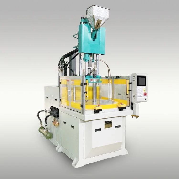
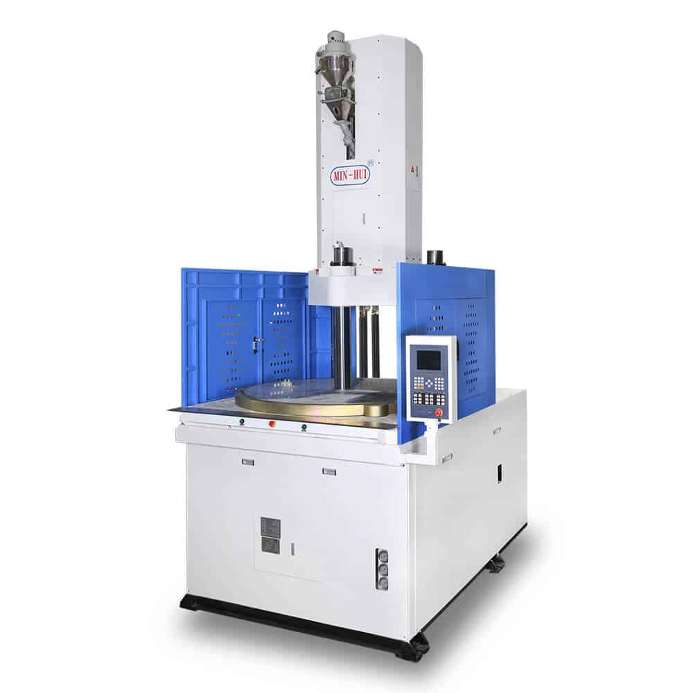
rotary table injection molding machine free sample
Inserts can be ergonomically encapsulated with our vertical ALLROUNDER injection molding machines. You can choose from the most extensive range of machines available in the industry, from the comprehensive spectrum of different ALLROUNDERs through to automated machine concepts and customer-specific special solutions.
The technology of our vertical ALLROUNDERs can be matched precisely to your specific injection molding tasks, while still maintaining maximum ergonomic efficiency. A wide range of clamping forces, flexible vertical and horizontal injection units, as well as task-specific equipment packages are available, for example for thermoset or silicone processing.

The present invention relates to a rotary device for a horizontal injection molding machine for turning mold portions or molded articles between the mold mounting plates about a vertical axis. The invention also relates to an injection molding machine equipped with such a rotary device.
An apparatus for holding and turning molds or mold parts in a horizontal injection molding machine is known, for example, from U.S. Pat. No. 4,330,257 and European Pat. No. EP 0 922 556 A1, with the horizontal injection molding machine having mold mounting plates between which a turret (mold center platen) is slideable in longitudinal direction of the machine and provided as mold carrier with prismatic cross section which is supported for rotation about an axis extending perpendicular to the longitudinal axis of the machine. In order to shift the turret in longitudinal axis of the machine, on the one hand, and to rotate the turret about an axis extending perpendicular to the longitudinal axis of the machine, a system is provided in which the turret is rotatably supported in carriers, with the carriers slideably guided and supported at least on both lower tie bars of the injection molding machine (U.S. Pat. No. 4,330,257) or on all four tie bars (European Pat. No. EP 0 922 556 A1). To permit a precise guidance of the carrier and of the attached turret, support and guiding elements are required which are of highly precise construction and sized in narrow tolerances and which are arranged at great distances from one another as a result of the system. Thus, this support reacts sensitively to temperature fluctuations, i.e. during cool-down period and accompanying shrinkage, the clearance in the bearings increases whereas during heating period and accompanying expansion there is a risk that the support and guiding elements get jammed on the tie bars. To prevent the latter, the tolerances in the support and guiding elements should not be too narrow, i.e. sized not too precisely. A further drawback resides in the fact that the tie bars are loaded by a significant weight (inadmissible bending) depending on the design of the turret and the carriers, and that the torques encountered during rotation of the turret must be absorbed entirely by the tie bars, resulting in particular during starting and braking of the rotational movement in significant stresses.
It would therefore be desirable and advantageous to provide an improved rotary device for horizontal injection molding machines, obviating prior art shortcomings. It would further be desirable and advantageous to provide an improved injection molding machine, equipped with a precisely supported and guided rotary device.
According to one aspect of the present invention, a rotary device for a horizontal injection molding machine, includes a base plate; a rotary table supported on the base plate for rotation about a vertical rotation axis; and drive means for rotating the rotary table, wherein the drive means includes a pivot pin extending downwards from the rotary table and projecting through the base plate.
The present invention resolves prior art problems by completely separating the guidance and the support of the rotary device from the tie bars. Thus, the tie bars are not unnecessarily exposed to stress, on the one hand, and the guidance and support can be dimensioned more precise compared to the prior art.
According to another feature of the present invention, the base plate has a substantially H-shaped, thereby establishing a stable support when the legs of the H-shaped base plate are sufficiently long, as well as allowing a simple withdrawal of a molded article into the free space between the legs of the H-shaped base plate. In connection with heavy mold center platens, it is advantageous to provide several linear guides and/or slideways and/or to so size the base plate as to reach to an area outside the zone of the mold mounting plates. By means of transport brackets and ring bolts, a complete stack mold can be dropped in closed state into the area between the mold mounting plates and mounted onto the rotary table, with centering elements being suitably provided for centering the center platen upon the rotary table.
According to another aspect of the present invention, a horizontal injection molding machine includes a machine bed defining a longitudinal axis, a first mold mounting plate fixedly secured onto the machine bed, a second mold mounting plate supported on the machine bed and movable relative to the first mold mounting plate, a rotary device arranged between the first and second mold mounting plates and including a base plate, a rotary table supported on the base plate for rotation about a vertical axis, and a drive mechanism for rotating the rotary table, and a shifting mechanism for displacing the rotary device in a direction parallel to the longitudinal axis, wherein the base plate and the second mold mounting plate are guided on different guides.
The invention will now be described in more detail by way of example with reference to a horizontal injection molding machine, generally designated by reference numeral 1 and having a machine bed 2 for support of a stack mold with a fixed mold mounting plate 3 carrying a mold portion 9 and a moving mold mounting plate 4 which carries a displaceable mold portion 10. The moving mold mounting plate 4 is guided on a machine bed guidance 23, 24, 25 and pulled by tie bars 5, 6, 7, 8 (FIG. 5) relative to the stationary mold mounting plate 3. Hydraulic cylinders 26 are shown for movement of the tie bars 5, 6, 7, 8 (only hydraulic cylinders 26 for the tie bars 6 and 8 are visible in FIGS. 1 and 5). Placed between the mold portions 9, 10 is a center platen 11, denoted in the following as swivel plate. The swivel plate 11 and the mold portions 9, 10 are each provided with, not shown, form recesses in confronting relationship to define respective cavities. Defined between the fixed mold portion 9 and the confronting side of the swivel plate 11 is the first phase of the stack mold, whereas the second phase of the stack mold is provided between the moving mold portion 10 and the confronting side of the swivel plate 11. Injection of material in the first phase is implemented by an injection unit 12 associated to the fixed mold portion 9, whereas the second phase injection is realized by a, not shown, generally L-shaped injection unit which is attached to the moving mold portion 10.
The swivel plate 11 is secured on a rotary device according to the invention, generally designated by reference numeral 40. The rotary device 40 includes a generally rectangular rotary table 13 for attachment of the swivel plate 11. The rotary table 13 is rotatably supported on a base plate 14 of substantially H-shaped configuration, as shown in particular in FIG. 4, thereby defining rear legs 15,16, forward legs 17, 18 and a croaspiece 50 interconnecting the rear and forward legs 15,16, 17,18. The crosspiece 50 and the rotary table 13 are so configured that a molded article is able to drop downwards into a free space between the legs 15, 16, 17, 18 of the base plate 14, whereby the legs 15, 16, 17, 18 of the H-shaped base plate 14 extend to an area in proximity to the mold mounting plates 3, 4 at formation of a slight distance (safety distance), when the stack mold is closed, as shown in FIG. 1 with respect to the rear legs 15, 16 As shown in particular in FIG. 5, the tie bars 5, 6, 7, 8 extend above the base plate 14.
A pivot pin 19 (rotor) points downwards from the rotary table 13 and is rotatably supported in a respective stator 20 and the base plate 14. The rotary table 13 is rotated on the machine bed 2 by a suitable drive mechanism, which includes e.g. a ring gear 43 mounted to the rotary table 13. The ring gear 43 is in mesh with a pinion 44 and driven by a motor 49, e.g. hydraulic motor or electric motor, as shown in particular in FIGS. 5 and 6.
The base plate 14 is supported on stable linear guides 23 (or on slideways) on the machine bed 2, with the machine bed 2 including stable linear rails or slideways 24, 25 for engagement of the complementary underside of the base plate 15. Disposed between the swivel plate 11 and the mold portion 9 in the first phase of the stack mold are at least two, preferably four, hydraulic release cylinders 28 in symmetric disposition, and disposed at the partition plane between the swivel plate 11 and the mold portion 10 in the second phase of the stack mold are at least two, preferably four, hydraulic release cylinders 32 in symmetric disposition, as shown in FIGS. 3 and 5. The release cylinders 18, 32 generate during opening movement a parallel, simultaneous short stroke as additional support for a parallel opening of the stack mold.
The movement of the rotary device 40 in longitudinal direction of the machine bed 2 is implemented by a shifting mechanism comprised of racks or steep-threaded spindles 36, 37, articulated on both sides to the mold mounting plates 9, 10, and gears 41 which are respectively attached to the base plate 14, as shown in particular in FIGS. 2 and 5. As shown in FIG. 4, the finished molded articles can be expelled into the free space between the legs 15, 16, 17, 18 of the H-shaped base plate 14 and carried off by a, not shown, subjacent conveyor belt. Thus, additional handling systems for withdrawal of the molded articles can be omitted. Transport brackets 39 and ring bolts 38 (FIG. 3) allow a simple assembly and disassembly of the entire stack mold as a unit. Of course, it is also possible to assemble and disassemble the mold components separately, when each mold component has ring bolts 38, and the transport brackets 39 are loosened.
Securement of the mold center platen 11 on the rotary table 13 is realized by providing in the lower region of the center platen 11 one or more grooves and by providing aligned bores in the portion of the center platen 11 that is placed on the rotary table 13, so that screw fasteners, not shown, can be screwed through these bores into the rotary table 13, with the screw heads being accessible via the grooves. Although not shown in detail, the rotary table 13 may be provided with centering members to allow proper alignment of the center platen 11.
Instead of a mold carrier of a stack mold, it is also possible to attach on the rotary device according to the invention other elements. For example, as shown in FIG. 7, a holding frame 45, i.e. a so-called index frame or a so-called index plate, may be provided for a molded article 46, to permit a turning of this molded article 46 from a first phase to a second phase between the mold portions 9 and 10
It is also possible to transmit a media such as water, oil, air, and electric signals between the center platen 11 and the rotary table 13, e.g. via a line 42.
While the invention has been illustrated and described as embodied in a rotary device for a horizontal injection molding machine, it is not intended to be limited to the details shown since various modifications and structural changes may be made without departing in any way from the spirit of the present invention.
While horizontal molding machines were the first of their kind to become a standard in plastic manufacturing, vertical molding machines may be a more sustainable way of molding for certain applications and many manufacturers are now to utilize their many advantages. With the advancement of injection molding becoming more standard in consumer products, it"s time to delve deep into the differences of its sub-groups.
This article will map out the difference between vertical and horizontal molding machines and will mention the advantages of vertical injection molding.
If you were to visit the American Injection Molding Institute, you would see a variety of molding machines. But only by working on the machines would you be able to know exactly what works best for you.
Vertical molding machines are more flexible in terms of efficient production cycles, cost, and types of products it can handle. Take insert molding as an example. This is when a pre-formed product is inserted into a mold that needs plastic formed around it (see pictures).
Attempting to do this on a horizontal machine would be difficult and awkward as you would be fighting gravity, slowing down production and raising the risk of bad parts. Horizontal molding creates even greater risks when it comes to medical injection molding, which requires high tolerance parts.
With a vertical molding machine, the parts can easily be placed in the mold quickly and comfortably without having to worry about the insert becoming misaligned.
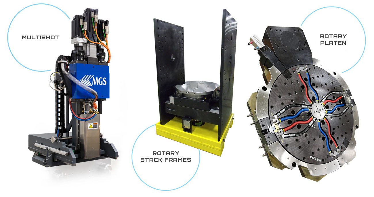
Book molds close on the inserts and hold the pieces tightly in place before, during, and after the molding process. Rotary tables can hold between 1-12 molds at a time and rotate giving the mold technician to time to replace the insert without holding up the molding process.
Multiple book molds on a rotary table can offer the fastest cycles and highest possible yields in molding. They also allow different molds for a family of products to be run at one time.
Another advantage of vertical injection moulding machine vs horizontal is that they take up well over half the space required for a horizontal molding machine. See the two machines pictured side-by-side:
Vertical injections can offer more control when the resin reaches the mold cavity through a short distance. Often times with horizontal machines, the plastic has to travel a longer distance to reach the mold which makes room for resin to cool too quickly and produce bad shots.
Clamping force is the amount of pressure required to keep the mold and product closed during the injection process. On vertical machines, especially when using book molds, the clamp is more of an added precaution since the top of the mold will be kept in place by gravity.
Shot size is the amount of molten plastic required in the injection process of the mold. Since the plastic is coming from the top, the size of the runner needed to complete a part is much less than that of a horizontal molding machine. This helps cut costs and reduce waste while keeping the process as efficient as possible.
Stuck on a project? Request a risk-free evaluation to see how medical injection molding experts Aberdeen Technologies can help move your project forward.

The hard plastic is molded for the first time, and the soft plastic is molded for the second time. Transparent for the first time, non-transparent for the second time. The plastic with high molding temperature is molded for the first time, and the plastic with low molding temperature is used for the second molding.
In this guide you"ll find everything you need to know about injection molding. Master the technology"s basic principles and learn actionable design tips fast that will save you time and cut costs.
In this section, we answer these questions and show you common examples of injection molded parts to help you familiarize yourself with the basic mechanics and applications of the technology.
Injection molding is a manufacturing technology for the mass-production of identical plastic parts with good tolerances. In Injection Molding, polymer granules are first melted and then injected under pressure into a mold, where the liquid plastic cools and solidifies. The materials used in Injection Molding are thermoplastic polymers that can be colored or filled with other additives.
Injection molding is so popular, because of the dramatically low cost per unit when manufacturing high volumes. Injection molding offers high repeatability and good design flexibility. The main restrictions on Injection Molding usually come down to economics, as high initial investment for the mold is required. Also, the turn-around time from design to production is slow (at least 4 weeks).
Injection molding is widely used today for both consumer products and engineering applications. Almost every plastic item around you was manufactured using injection molding. This is because the technology can produce identical parts at very high volumes (typically, 1,000 to 100,000+ units) at a very low cost per part (typically, at $1-5 per unit).
But compared to other technologies, the start-up costs of injection molding are relatively high, mainly because custom tooling is needed. A mold can cost anywhere between $3,000 and $100,000+, depending on its complexity, material (aluminum or steel) and accuracy (prototype, pilot-run or full-scale production mold).
All thermoplastic materials can be injection molded. Some types of silicone and other thermoset resins are also compatible with the injection molding process. The most commonly used materials in injection molding are:
Even if we take into account all other possible manufacturing technologies, injection molding with these four materials alone accounts for more than 40% of all plastic parts produced globally every year!
In 1869, John Wesley Hyatt invented celluloid, the first practical artificial plastic intended to replace ivory for the production of... billiard balls! Early injection molding machines used a barrel to heat up the plastic and a plunger to inject it to the mold.
Today, injection molding is a $300 billion market. 5+ million metric tons of plastic parts are produced with injection molding globally each year. Recently, the demand of biodegradable materials is increasing for environmental reasons.
In this section, we examine the purpose of each of these systems and how their basic operation mechanics affect the end-result of the Injection molding process.
The purpose of the injection unit is to melt the raw plastic and guide it into the mold. It consists of the hopper, the barrel, and the reciprocating screw.
After the part is ejected, it is dispensed on a conveyor belt or in a holding container. Usually, injection molded parts are ready to use right away and require little to no post-processing.
It usually makes up the largest portion of the start-up costs in injection molding: the cost of a typical mold starts at approximately $2,000-5,000 for a simple geometry and relatively small production runs (1,000 to 10,000 units) and can go upwards to $100,000 for molds optimized for full-scale production (100,000 units or more).
Molds are usually CNC machined out of aluminum or tool steel and then finished to the required standard. Apart from the negative of the part, they also have other features, like the runner system that facilitates the flow of the material into the mold, and internal water cooling channels that aid and speed up the cooling of the part.
Recent advances in 3D printing materials have enabled the manufacturing of molds suitable for low-run injection molding (100 parts or less) at a fraction of the cost. Such small volumes were economically unviable in the past, due to the very high cost of traditional mold making.
Interesting fact: About 50% of the typical injection molding cycle is dedicated to cooling and solidification. Minimizing the thickness of a design is key to speed up this step and cuts costs.
Injection molded parts have two sides: the A side, which faces the cavity (front half of the mold) and the B side, which faces the core (back half of the mold). These two sides usually serve different purposes:
The runner spreads the melted plastic along the face where the two halves of the mold meet and connects the spur to the gates. There may be one or more runners, guiding the material towards one or multiple parts. The runner system is cut off from the part after ejection. This is the only material waste in injection molding, 15-30% of which can be recycled and reused.
Edge gates inject material at the parting line of the two halves of the mold and are the most common gate type. The runner system has to be removed manually later, leaving a small imperfection at the injection point.
Hot tips are directly connected to the spur and inject plastic from the top side of the part. No material is wasted this way on the runner system making them ideal for large scale production, but a dimple will be visible at the injection point.
On the far side of an injection molding machine is the clamping system. The clamping system has a dual purpose: it keeps the 2 parts of the mold tightly shut during injection and it pushes the part out of the mold after it opens.
Alignment of the different moving parts of the mold is never perfect though. This causes the creation of 2 common imperfections that are visible on almost every injection molded part:
Injection molding is an established manufacturing technology with a long history, but it"s constantly being refined and improved with new technological advancements.
Below is a quick rundown of the key advantages and disadvantages of injection molding to help you understand whether it"s the right solution for your application.
Injection molding is the most cost-competitive technology for manufacturing high volumes of identical plastic parts. Once the mold is created and the machine is set up, additional parts can be manufactured very fast and at a very low cost.
The recommended minimum production volume for injection molding is 500 units. At this point economies of scale start to kick-in and the relatively high initial costs of tooling have a less prominent effect on the unit price.
Almost every thermoplastic material (and some thermosets and silicones) can be injection molded. This gives a very wide range of available materials with diverse physical properties to design with.
Parts produced with injection molding have very good physical properties. Their properties can be tailored by using additives (for example, glass fibres) or by mixing together different pellets (for instance, PC/ABS blends) to achieve the desired level of strength, stiffness or impact resistance.
The typical injection molding cycle lasts 15 to 60 seconds, depending on the size of the part and the complexity of the mold. In comparison, CNC machining or 3D printing might require minutes to hours in order to produce the same geometry. Also, a single mold can accomodate multiple parts, further increasing the production capabillities of this manufacturing process.
The injection molding process is highly repeatable and the produced parts are essentially identical. Of course, some wear occurs to the mold over time, but a typical pilot-run aluminum mold will last 5,000 to 10,000 cycles, while full-scale production molds from tool steel can stand 100,000+ cycles.
Typically, injection molding will produce parts with tolerances of ± 0.500 mm (0.020’’). Tighter tolerances down to ± 0.125 mm (0.005’’) are also feasible in certain circumstances. This level of accuracy is enough for most applications and comparable to both CNC machining and 3D printing.
A key strength of injection molding is it can produce finished products that need little to no extra finishing. The surfaces of the mold can be polished to a very high degree to create mirror-like parts. Or they can be bead blasted to create textured surfaces. The SPI standards dictate the level of finishing that can be achieved.
The main economic restriction of injection molding the the high cost of tooling. Since a custom mold has to be made for each geometry, the start-up costs are very high. These are mainly related to the design and manufacturing of the mold which typically costs between $5,000 and $100,000. For this reason, injection molding is only economically viable for productions larger than 500 units.
After a mold is manufactured, it"s very expensive to modify. Design changes usually require the creation of a new mold from scratch. For this reason, correctly designing a part for injection molding is very important.
In Part 2, we list the most important design considerations to keep in mind while designing for injection molding. It Part 5, we"ll also see how you can mitigate the risk by creating physical prototypes of your parts.
The typical turnaround for injection molding varies between 6-10 weeks. 4-6 weeks to manufacture the mold, plus 2-4 more weeks for production and shipping. If design changes are required (something quite common) the turnaround time increases accordingly.
In comparison, parts made in a desktop 3D printer can be ready for delivery overnight, while industrial 3D printing systems have a typical lead time of 3-5 days. CNC machined parts are typically delivered within 10 days or as fast as 5 days.
If you look around you right now, you"ll see at least a few products that were manufactured with injection molding. You"re probably looking at one right now actually: the casing of the device you are using to read this guide.
We"ve collected some examples of products commonly manufacturing with injection molding to help get a better understanding of what can be achieved with this manufacturing process.
Lego bricks are one of the most recognizable examples of injection molded parts. They"re manufactured using molds, like the one in the picture, which produced 120 million lego bricks (that"s 15 million cycles) before it was taken out of commission.
For example, bottle caps are injection molded from Polypropylene. Polypropylene (PP) has excellent chemical resistance and is suitable to come in contact with food products.
On bottle caps, you can also see all the common unavoidable injection molding imperfections (parting line, ejector marks etc.) and common design features (ribs, stripping undercuts etc.).
Model airplanes are another common example of injection molded parts. The material used here is mostly Polystyrene (PS), for its low cost and ease of molding.
Almost every plastic component in the interior of a car was injection molded. The 3 most common injection molding materials used in the automotive industry are Polypropylene (PP) for non-critical parts, PVC for its good weather resistance and ABS for its high impact strength.
The enclosures of almost every mass-produced consumer electronic device was injection molded. ABS and polystyrene (PS) are prefered here for their excellent impact resistance and good electrical insulation.
Medical grade silicone is one of the more popular materials in the medical industry. Silicone is a thermoset though, so special machinery and process control are required, increasing the cost.
In this section, we outline common defects of injection molding and basic and advanced guidelines to follow when designing parts, including recommendations for keeping the costs to a minimum.
Here is a list of defects to keep in mind while designing a part for injection molding. In the next section, we"ll see how you can avoid each of them by following good design practices.
Trapped air in the mold can inhibit the flow of the material during injection, resulting in an incomplete part. Good design can improve the flowability of the melted plastic.
The simplest mold (the straight-pull mold) consist of 2 halves. Features with undercuts (such as the teeth of a thread or the hook of a snap-fit joint) may not be manufacturable with a straight-pull mold though. This is either because the mold cannot be CNC machined or because the material is in the way of ejecting the part.
Undercuts in injection molding are part features that cannot be manufactured with a simple two-part mold, because material is in the way while the mold opens or during ejection.
Below are some examples of how injection molded parts can be redesigned to avoid undercuts: essentially, material is removed in the area under the undercut, eliminating the issue altogether.
Learn how to design the most common features encountered in injection molded parts with these practical guidelines. Use them to improve the functionality of your designs, while still complying with the basic design rules.
There are 3 ways to add fasteners to an injection molded part: by designing a thread directly on the part, by adding a boss where the screw can be attached, or by including a threaded insert.
Modelling a thread directly on the part is possible, but not recommended, as the teeth of the thread are essentially undercuts, increasing drastically the complexity and cost of the mold (we will more about undercuts in a later section). An example of an injection molded part with a thread are bottle caps.
Bosses are very common in Injection Molded parts and are used as points for attachment or assembly. They consist of cylindrical projections with holes designed to receive screws, threaded inserts, or other types of fastening and assembly hardware. A good way to think of a boss is as a rib that closes on itself in a circle.
Metal threaded inserts can be added to plastic Injection Molded parts to provide a durable threaded hole for fasteners such as machine screws. The advantage of using inserts is that they allow many cycles of assembly and disassembly.
Inserts are installed in Injection Molded parts through thermal, ultrasonic or in-mold insertion. To design a boss that will receive a threaded insert, use similar guidelines as above, using the diameter of the insert as the guiding dimension.
The material used to injection mold a living hinge must be flexible. Polypropylene (PP) and Polyethylene (PE) are good choices for consumer application and Nylon (PA) for engineering uses.
Once the mold is manufactured, these complex parts can be reproduced at a very low cost. But changes to the mold design at later stages of development can be very expensive, so achieving the best results on the first time is essential. Follow the guidelines below to avoid the most common defects in injection molding.
A wall thickness between 1.2 mm and 3 mm is a safe value for most materials. The next table summarises specific recommended wall thicknesses for some of the most common injection molding materials:
Injection molding is compatible with a wide range of plastics. In this section, you"ll learn more about the key characteristics of the most popular materials. We"ll also discuss the standard surface finishes that can be applied to injection molded parts.
An additive that is commonly used to improve the stiffness of the injection molded parts is fiberglass. The glass fibers can be mixed with the pellets at ratios of 10%, 15% or 30%, resulting in different mechanical properties.
Surface finishes can be used to give an injection molded part a certain look or feel. Besides cosmetic purposes surface finishes can also serve technical needs. For example, the average surface roughness (Ra) can dramatically influence the lifetime of sliding parts such as plain bearings.
A high glossy mold finish is not equivalent to a high glossy finished product. It is significantly subject to other factors such as plastic resin used, molding condition and mold design. For example, ABS will produce parts with a higher glossy surface finish than PP. To find the recommended material and surface finish combination visit the appendix.
For larger volumes to full-scale production (10,000 to 100,000+ units), the contribution of the tooling costs to the overall cost is overshadowed by the material and production costs. So, your main design efforts should focus on minimizing both the volume part and the time of the molding cycle.
Reducing the wall thickness of your part is the best way to minimize the part volume. Not only does it mean less material is used, but also the injection molding cycle is greatly accelerated.
Thinner walls mean that the mold can be filled quicker. More importantly, parts thinner parts cool and solidify much faster. Remember that about half the injection molding cycle is spent on the solidification of the part while the machine is kept idle.
For lower volume productions (less than 1000 parts), it may be more cost effective to use a secondary operation to complete your injection molded parts. For example, you could drill a hole after molding rather than using an expensive mold with side-action cores.
Once your design ready and optimized for injection molding, what’s next? In this section we"ll take you through the steps needed to start manufacturing with injection molding.
The minimum order volume for injection molding is 500 units. For these quantities, the molds are usually CNC machined from aluminum. Aluminum molds are relatively easy to manufacture and low in cost (starting at about $3,000 to $5,000) but can withstand up to 5,000 - 10,000 injection cycles.
For these volumes, the molds are CNC machined from tool steel and can withstand millions of Injection molding cycles. They are also equipped with advanced features to maximize production speeds, such as hot-tip gates and intricate cooling channels.
Here, we touched upon all you need to get you started with injection molding. There is plenty more to learn though in our Knowledge Base - a collection of technical articles on all manufacturing technologies, written by experts from Hubs and the manufacturing industry.

Plastic molding began in the late 1800’s to fill the need for plastic billiard balls as opposed to the commonly used ivory billiard balls of the time. In 1868, John Wesley Hyatt invented a way to make billiard balls by injecting celluloid into a mold. Four years later, Hyatt and his brother invented and patented a machine to automate the process. This was the first plastic injection molding machine in existence and it used a basic plunger to inject plastic into a mold through a heated cylinder.
In 1946, the screw injection molding machine was invented by James Hendry, which replaced the plunger injection technique. This is the technique most commonly used today.[2]
Plastics were introduced into the process in the early 1950’s, when rotational molding was first used to manufacture doll heads. And then in the 1960’s the modern process of rotational molding that allows us to create large hollow containers with low-density polyethylene was developed. In recent history, process improvements, better equipment, and plastic powder developments have sped up the process of creating finished products which has caused rotational molding to grow rapidly in popularity.[3]


 8613371530291