
3 jaw chuck for rotary table free sample

6" PRECISION 3 slot ROTARY TABLE /HORIZONTAL&VERTICALwith 6" 3-jaw self-centering chuck top&bottom reversible jaws, front mounting. All bolts and T-nuts to mount the chuck included.

Available for the Fusion Edge/Pro 36 is the 3-Jaw Chuck Rotary Attachment. With this attachment, objects are clamped into the device"s 3-jaw chuck, allowing you to rotate cylindrical or oddly-shaped items in applications that demand more precise alignment.

New: A brand-new, unused, unopened, undamaged item in its original packaging (where packaging is applicable). Packaging should be the same as what is found in a retail store, unless the item was packaged by the manufacturer in non-retail packaging, such as an unprinted box or plastic bag. See the seller"s listing for full details.See all condition definitionsopens in a new window or tab

Why do we have to do that? Quite simply, you have forbidden us to watch Your steps on our site with Google Analytics. That sounds dramatically to You, we know. But look at it: we do not even know who YOU are, we just see that SOMEONE looks at our pages, how he/she does that, how long this SOMEONE lingers on the respective pages, etc. We do not know who You are, whether You are male or female, how old You are, how Your weight is - no idea. Nor do we pass this data on to Google, we don not have them not at all! Nevertheless, this data of SOMEONE will provide us with valuable information about our site, we want You to like everything here, that You feel good and - of course - buy our products ...
So we can see where there are problems. If many visitors leave our site during the purchase process while choosing the payment method, we know that something is wrong and can improve it. Sounds good, right? Thats good for You and good for us. So it´s a win-win situation. So let us accompany You on Your way through our store. Deal?

This is a modification of our 4″ Manual Rotary Table. This modification came about after requests from our laser engraving customers. They wanted a rotary table that had a larger through-hole to which they could mount our chucks.
This version of the Sherline rotary table has a Nickel-Teflon plating on the tabletop because it was designed to be used in an everyday production environment. This gives the table a rust-resistant surface that is hard and has added lubrication qualities.
The table is 2″ high and 4″ (100mm) in diameter. The main components have been machined from solid bar stock steel, and the complete unit weighs seven pounds. The table has been engraved with a laser, giving sharp and precise lines every 5°, numbered every 15°. These lines are calibrated with the 72-tooth worm gear that is driven by the handwheel or stepper motor. The handwheel is divided into 50 parts, making each line on the handwheel 1/10°. This allows a circle to be divided into 3600 increments without interpolation. Seventy-two revolutions of the handwheel rotate the table one revolution.
NOTE: You can have your manual rotary table upgraded to CNC-ready, but this is done as a factory-only replacement. You will need to ship your manual rotary table back to our factory for the conversion.

The indexing head doesn"t only look great, but allow you to do more with your milling machine: measuring specific angles and dividing a circle into equidistant arcs. It comes with 3 interchangeable indexing plates and a tailstock to ensure more precise and stable work. It will be your perfect assistant to machine the flutes of a milling cutter, cut the teeth of a gear, mill curved slots, or drill a bolt hole circle around the circumference of a part.
By turning the 1st level that extrudes the pin, the pin goes into the plate and you can divide the full circle into 2, 3, 4, 6, 8, 12, or 24 divisions. The other level prevents the spindle from vibrating during machining.
The high precision performance of the indexing head is achieved with indirect indexing plates A, B, and C. All divisions 2-50 can be done, but some from 51 to 380 cannot be obtained. Check the manual before setting.

I"d like to be able to put my 10" & 12" A (not sure which one, but short tapered nose, four bolts) series 3 & 4 jaw chucks on my 10" Phase II rotary table for doing bolt holes, gears; I don"t happen to have any smaller chucks. The center of the table has a MT2 taper I believe, which might serve to indicate where the center is but isn"t strong enough to coerce the chuck into the right position, even sitting free on the table. I guess the 4 jaw doesn"t need to be centered - only the work held by the chuck does - but since many things that need bolt patterns are already round, I could save some time by using the 3 jaw.

I"m a wanna-be machinist newbie. I have a small mill (no lathe). I obtained this small 6" rotary table (a Griz product). I would like to get a small 3-jaw chuck mounted to it, but have NO CLUE as to how to choose a chuck that will be compatible with this RoTab. Am I looking for a 6" chuck? Or 4"? I can"t go too "tall" or I waste all my Z axis. I don"t even know how the chuck would mount to the RoTab. The hole in the center is a MT#2, would a chuck use the MT? Or attached how?
Can someone guide me to some options regarding how to get a chuck on here, where to find the components needed? I am not looking for gold-plated accuracy. (It"s just an inexpensive $900 ChiCom mill with an inexpensive $250 ChiCom RoTab. Not proud of it, but I"m lucky to have it, and it works good enough.) In fact I"d love to buy a chuck used if possible and save some coin. Ideas?
More info on my intended useage of chuck-on-rotab, if you are interested: This RoTab will mount horizontal or vertical. With the RoTab in the vertical position, with its associated tailstock, I believe you can "fake" some lathe operations on a mill. I need to do some small lathe operations with it, which will entail bringing down an endmill to the work and then slowly turning the RoTab. So sort of reverse of a lathe, in this setup the bit is powered and the work is being turned slowly by hand. Yeah, I wish had a lathe but in this obanomy, you make do with what you got.
Alternately, I think I can do some vertical lathing without the RoTab. If the stock is small enough to go into the mill"s chuck (5/8 max) and stout enough to hang free, some lathing can be done by clamping a lathe bit in the vise and running it up and down the work using the Z axis. For small work only.
I suppose you could also chuck a larger round piece in the rotab/chuck (with the rotab/chuck in the horizontal position, and the work sticking up vertically), and use an endmill to make bushings, and other short, squat round work, etc. by spinning the work in the rotab/chuck against the endmill.

This website is using a security service to protect itself from online attacks. The action you just performed triggered the security solution. There are several actions that could trigger this block including submitting a certain word or phrase, a SQL command or malformed data.

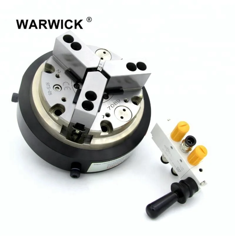
The standard 3-jaw chuck is designed to hold a part and is opened and closed via a removable handle that drive a scroll to evenly open and close the chuck jaws. The chuck has master jaws that allow for hard and soft jaws to be installed. The standard chuck package includes an adapter plate to allow it to be mounted to the rotary table spindle or faceplate. Most 3-jaw chucks are adjustable to allow you to align the rotation of the chuck to run true with the rotation of the rotary table.

I have a 210, however it doesnt make much difference in the size. most of these guys made good points only thing I can add about the 2 piece jaw set is we cut our jaws for the 6" chuck we put on our 210. sometimes we have to use full pie jaws as well. I dont like the hard jaws that come with the cheaper chucks as they tend to not hold evenly and they will make parts.
I use our lathes collet chucks for the 210 also( you can for the 160 units too. so I have 5c 16c 20s avail. when I need them. just have to make a collet locking bar which is pretty simple. you will also might have to make a spacer to slip over the back side of collet so the face of the locking bar can ride on it.
A chuck is a specialized type of clamp used to hold an object with radial symmetry, especially a cylinder. In a drill, a mill and a transmission, a chuck holds the rotating tool; in a lathe, it holds the rotating workpiece.
Chucks commonly use jaws to hold the tool or workpiece. The jaws (sometimes called dogs) are typically arranged in a radially symmetrical pattern like the points of a star. Jawed chucks may require a wrench-like device called a chuck key to be tightened or loosened, but other jawed chucks may be tightened or loosened by hand force alone, offering convenience at the expense of gripping force. Chucks on some lathes have jaws that move independently, allowing them to hold irregularly shaped objects. More complex designs might include specially shaped jaws, greater numbers of jaws, or quick-release mechanisms.
Instead of jaws, a chuck may use magnetism, vacuum, or collets, which are flexible collars or sleeves that fit closely around the tool or workpiece and grip it when squeezed.
Self-centering three-jaw chuck and key with one jaw removed and inverted showing the teeth that engage in the scroll plate. The scroll plate is rotated within the chuck body by the key, the scroll engages the teeth on the underside of the jaws which moves the three jaws in unison, to tighten or release the workpiece.
A self-centering chuck, also known as a scroll chuck,dogs (usually called jaws), interconnected via a scroll gear (scroll plate), to hold onto a tool or workpiece. Because they most often have three jaws, the term three-jaw chuck without other qualification is understood by machinists to mean a self-centering three-jaw chuck. The term universal chuck also refers to this type. These chucks are best suited to grip circular or hexagonal cross-sections when very fast, reasonably accurate (±0.005 inch [0.125 mm] TIR) centering is desired.
Sometimes this type of chuck has four or six jaws instead of three. Four-jawed chucks are primarily useful for gripping square or octagon material, while six-jawed chucks hold thin-walled tubing and plastic materials with minimum distortion.
There are hybrid self-centering chucks that have adjustment screws that can be used to further improve the concentricity after the workpiece has been gripped by the scroll jaws. This feature is meant to combine the speed and ease of the scroll plate"s self-centering with the run-out eliminating controllability of an independent-jaw chuck. The most commonly used name for this type is a brand name, Set-Tru. To avoid undue genericization of that brand name, suggestions for a generic name have included "exact-adjust".
Top: an assembled keyless chuck. This type of chuck is tightened by twisting the body using firm hand pressure only. While convenient, this feature can cause the chuck to tighten too much when high torque is applied. Bottom: the widely used keyed type of drill chuck with its key. The arbor is shown separately to the right. These chucks require a toothed key to provide the necessary torque to tighten and loosen the jaws. When the key is turned its teeth mate with teeth on the chuck, turning an internal screw which in turn moves the threaded jaws in or out along a tapered surface. The taper allows the jaws to clamp drill shanks of a range of diameters. The end view shows the three small jaws that slide within the body.
A drill chuck is a specialised self-centering, three-jaw chuck, usually with capacity of 0.5 in (13 mm) or less, and rarely greater than 1 in (25 mm), used to hold drill bits or other rotary tools. This type of chuck is used on tools ranging from professional equipment to inexpensive hand and power drills for domestic use.
Some high-precision chucks use ball thrust bearings to reduce friction in the closing mechanism and maximize drilling torque. One brand name for this type of chuck, which is often genericized in colloquial use although not in catalogs, is Super Chuck.
A pin chuck is a specialized chuck designed to hold small drills (less than 1 mm (0.039 in) in diameter) that could not be held securely in a normal drill chuck. The drill is inserted into the pin chuck and tightened; the pin chuck has a shaft which is then inserted into the larger drill chuck to hold the drill securely. Pin chucks are also used with high-speed rotary tools other than drills, such as die grinders and jig grinders.
An older and larger 4 jaw chuck. Note how it is able to grip an irregularly cut piece of used metal. Though not found on small chucks it is common for larger chucks (the one in the second photo was made around 1900 and is 24" in diameter) to have many of the features of a faceplate. The jaws are stepped on one side and full height for gripping on the other and are reversible. Generally the jaws are usable for holding either outside as shown here, or inside as in gripping the inside of a pipe.
On an independent-jaw chuck, each jaw can be moved independently. Because they most often have four jaws, the term four-jaw chuck without other qualification is understood by machinists to mean a chuck with four independent jaws. The independence of the jaws makes these chucks ideal for (a) gripping non-circular cross sections and (b) gripping circular cross sections with extreme precision (when the last few hundredths of a millimeter [or thousandths of an inch] of runout must be manually eliminated). The non-self-centering action of the independent jaws makes centering highly controllable (for an experienced user), but at the expense of speed and ease. Four-jaw chucks are almost never used for tool holding. Four-jaw chucks can be found on lathes and indexing heads.
Self-centering chucks with four jaws also can be obtained. Although these are often said to suffer from two disadvantages: inability to hold hex stock, and poor gripping on stock which is oval, only the latter is true. Even with three jaw self centering chucks, work which is not of uniform section along the work (and which is not free of spiral or "wind") should not be gripped, as the jaws can be strained and the accuracy permanently impaired.
A spider is a simple, relatively inexpensive, limited-capability version of an independent-jaw chuck. It typically consists of a ring of metal with screw threads tapped radially into it, in which screws (hex cap, socket hex cap, or set screws) serve as independent jaws. Spiders can serve various purposes:
For special purposes, chucks are available with six or eight jaws. These are usually of the self-centering design, and may be built to very high standards of accuracy. However, it is a misconception that such chucks necessarily offer more precision in holding solid workpieces than conventional three-jawed self-centering chucks. Indeed, hot-rolled or other imperfectly round workpieces may "teeter" insecurely between opposing jaws of scroll chucks having even numbers of jaws, in the same manner that a four-legged stool teeters on a rough floor while a three-legged stool never does. The primary purpose of six- and eight-jawed chucks is to hold thin-walled tubing with minimum deformation. By having twice as many clamping points, a six-jaw chuck induces less than half as much clamping distortion in a thin-walled workpiece, compared to a three-jawed chuck.
Two-jaw chucks are available and can be used with soft jaws (typically an aluminium alloy) that can be machined to conform to a particular workpiece. It is a short conceptual leap from these to faceplates holding custom fixtures, wherein the part is located against fixed stops and held there with toggle clamps or toe clamps.
Many chucks have removable jaws (often the top part is removable leaving the base or "master jaw" assembled with the scroll), which allows the user to replace them with new jaws, specialised jaws, or soft jaws. Soft jaws are made of soft materials such as soft (unhardened) metal, plastic, or wood. They can be machined as needed for particular setups. The typical interface between the master jaw and the removable jaw is a matching pair of serrated surfaces, which, once clamped by the mounting screws, cannot allow relative slipping between the two parts.
A collet, one type of chuck, is a sleeve with a (normally) cylindrical inner surface and a conical outer surface. The collet can be squeezed against a matching taper such that its inner surface contracts to a slightly smaller diameter, squeezing the tool or workpiece whose secure holding is desired. Most often this is achieved with a spring collet, made of spring steel, with one or more kerf cuts along its length to allow it to expand and contract. An alternative collet design is one that has several tapered steel blocks (essentially tapered gauge blocks) held in circular position (like the points of a star, or indeed the jaws of a jawed chuck) by a flexible binding medium (typically synthetic or natural rubber). The Jacobs Rubber-Flex brand is a name that most machinists would recognize for this type of collet chuck system.
Regardless of the collet design, the operating principle is the same: squeeze the collet radially against the tool or workpiece to be held, resulting in high static friction. Under correct conditions, it holds quite securely. Almost all collet chucks achieve the radial squeezing motion via moving one or more male-female pairs of tapered (conical) surfaces axially, which produces the radial squeezing in a highly concentric manner. Depending on the collet design, it can be either pulled (via a threaded section at the rear of the collet) or pushed (via a threaded cap with a second taper) into a matching conical socket to achieve the clamping action. As the collet is forced into the tapered socket, the collet will contract, gripping the contents of the inner cylinder. (The axial movement of cones is not mandatory, however; a split bushing squeezed radially with a linear force—e.g., set screw, solenoid, spring clamp, pneumatic or hydraulic cylinder—achieves the same principle without the cones; but concentricity can only be had to the extent that the bushing"s diameters are perfect for the particular object being held. Thus only in toolroom contexts, such as machine tool tooling creation and setup, is this common.)
One of the corollaries of the conical action is that collets may draw the work axially a slight amount as they close. Collet chuck systems that make no provision to prevent this draw-in are often called draw-in collet chucks, in contrast to systems which circumvent this movement, usually by pushing the tapered closing ring toward the collet rather than pulling the collet into the ring. Such non-draw-in types are often called "dead-length" or "non-draw-in" collet chucks. Draw-in is not always a problem, but avoiding it can be helpful on some work where failing to account for it might result in inaccuracy on part overall length, shoulder lengths, etc.
Collets are most commonly found on milling machines, lathes, wood routers, precision grinders, and certain handheld power tools such as die grinders and rotary tools. There are many different systems, common examples being the ER, 5C, and R8 systems. Collets can also be obtained to fit Morse or Brown and Sharpe taper sockets.
Typically collets offer higher levels of precision and accuracy than self-centering chucks, and have a shorter setting up time than independent-jaw chucks. The penalty is that most collets can only accommodate a single size of workpiece. An exception is the ER collet which typically has a working range of 1 mm (about 0.04 in).
Developed by Bosch in 1975 for hammer drills, the SDS System uses an SDS Shank which is a cylindrical shank with indentations to be held by the chuck.
A 6 mm shank with two open grooves interacting with the driving wedges and two closed grooves held by locking balls. This is the newest size introduced in 2011 for the Bosch Uneo series and takes concrete drills up to 10 mm diameter.
A 10 mm shank with two open grooves interacting with the driving wedges and two closed grooves held by locking balls. This is the most common size and takes a hammer up to 4 kg. The wedges grip an area of 75 mm2 (0.116 sq in) and the shank is inserted 40 mm into the chuck.
A 14 mm shank similar to SDS-plus, designed for hammers from 2 to 5 kg. The grip area is increased to 212 mm2 (0.329 sq in) and the shank is inserted 70 mm. This size remained uncommon and was discontinued in 2009.
An 18 mm shank with three open grooves and locking segments rather than balls. It is designed for hammers over 5 kg. The wedges grip an area of 389 mm2 (0.603 sq in) and the shank is inserted 90 mm.
Many SDS drills have a "rotation off" setting, which allows the drill to be used for chiselling. The name SDS comes from the German Steck-Dreh-Sitz (insert-drill-attachment). In German-speaking countries the acronym Spannen durch System (Clamping System) was also used, though Bosch now uses Special Direct System internationally.
Commercial production machining now makes use of increasingly advanced chucks which have not only indexable positioning but also indexable clamping.hydraulically controlled. The clamping is often done with each pair of jaws consisting of one fixed jaw and one movable jaw (hydraulically actuated), thematically similar to advanced milling vises. This method of clamping brings the high precision and repeatability of such vises to a chucking application. Such chucks offer the centering precision of traditional independent-jaw chucks with the chucking speed and ease of traditional three-jaw self-centering scroll chucks. They have expensive initial cost (compared with traditional chucks), but such initial cost pays for itself and then lowers ongoing marginal costs in commercial production-run environments.
It is also possible nowadays to build CNC chucks in which the position and clamping pressure of each jaw can be precisely controlled with CNC, via closed-loop positioning and load monitoring. In essence, each jaw is one independent CNC axis, a machine slide with a leadscrew, and all four or six of them can act in concert with each other. Although this idea is conceptually interesting, the simpler chucking systems mentioned in the previous paragraph are probably a marketplace winner over this alternative for most applications, because they supply the same capabilities via a simpler, less expensive solution.
Used for holding ferromagnetic workpieces, a magnetic chuck consists of an accurately centred permanent magnet face. Electromagnets or permanent magnets are brought into contact with fixed ferrous plates, or pole pieces, contained within a housing. These pole pieces are usually flush with the housing surface. The part (workpiece) to be held forms the closing of the magnetic loop or path, onto those fixed plates, providing a secure anchor for the workpiece.
Commonly used for holding silicon wafers during lithography processes, an electrostatic chuck comprises a metal base-plate and a thin dielectric layer; the metal base-plate is maintained at a high-voltage relative to the wafer, and so an electrostatic force clamps the wafer to it. Electrostatic chucks may have pins, or mesas, the height of which is included in the reported dielectric thickness; a design by Sandia National Laboratory uses a patterned silicon-dioxide dielectric to form the pins.
A vacuum chuck is primarily used on non-ferrous materials, such as copper, bronze, aluminium, titanium, plastics, and stone. In a vacuum chuck, air is pumped from a cavity behind the workpiece, and atmospheric pressure provides the holding force. Vacuum produces a hold down pressure of 14.7 psi (101 kPa) at sea level, decreasing at higher elevations where the atmospheric pressure is lower. The decrease in holding pressure is roughly 0.5 psi per 1000" above sea level.
Tools: vise (especially with a wooden jig or soft jaw made for this purpose); hammer (especially nonmarring hammer or rubber mallet); arbor press or shop press (the latter two require skill to avoid damaging the chuck).
A backplate with threads may screw onto a threaded spindle nose (for lathe work) or onto an adapter plate with the same nose, to be mounted on the table of milling machines or surface grinding machines. This "threaded spindle nose" type of mounting was the typical method in the 19th century through 1930s. It is simple and useful, but the degree of control of concentricity is not quite good enough to be foolproof for high-speed, high-precision work (high precision can be achieved, but the time and skill involved in the setups makes it a poor choice now that better options exist, such as the cam-lock spindle noses described below). Threaded spindle noses are still built on new machine tools, but only of the low-end variety (hobbyist, least-expense MRO, etc.). High-capital manufacturing (where high upfront expense yields lowest possible unit expense for mid- to high-volume part counts of high-precision parts) has moved away from this type of mounting. The exact-adjust (Set-Tru) concept is one way to chase high concentricity on threaded spindle noses with some relative degree of ease.
A common solution on smaller lathes is a broad flanged end to the spindle with a concentric raised circular register matching a recess in the chuck or its backplate. The register is normally shallow and parallel sided and a light push fit in the female register of the chuck. The chuck is held in place with bolts through clearance holes that do not affect the alignment which is entirely provided by the register. This arrangement has excellent repeatability but is slow in a production situation.
A backplate with a female (self-releasing) taper may seat on the matching male taper of the tapered spindle nose (for lathe work) or of an adapter plate with the same nose, to be mounted on a table. This system improves the repeatability of the mounting concentricity down to a very small total indicated runout (TIR) value. Subtypes:
The chuck may be held against the taper with a threaded retainer ring (large thin nut), typically wrenched with a spanner wrench of the pin or hook variety. The peak of popularity for building this type of spindle nose was the 1940s and 1950s.
The chuck may be held against the taper with cam-lock posts that wedge into a stuck-fast position. Industry-standard spindle nose designs allow wide interchangeability. This cam lock spindle nose system replaced the earlier systems on most machine tools in the 1960s.
Many lathes that run collet chucks have dedicated collet-closer setups whereby there is no backplate, and the spindle nose contains the female taper for either the collet"s male outer taper, or a sleeve that will hold it. A hollow drawbar passes back through the headstock to its back side, where a closer mechanism is mounted. The latter allows easy, rapid opening and closing of the collet. The drawbar"s inner diameter determines the through-the-spindle bar diameter capacity of the lathe. Some collet-closer systems even allow opening and closing without stopping the spindle rotation. The closer on a manual lathe is either lever-style or handwheel-style. The closer on a CNC lathe is powered (electric, hydraulic, or pneumatic), and it may be controlled by various means: a foot pedal that the operator steps on when desired; a line in the program (for opening and closing under program control); or a button on the control panel.
The Jacobs type chuck, with three converging splines or jaws, is perhaps the most usual design. This one is tightened with a key, but some types may be sufficiently tightened by hand
The original forms of workholding on lathes were between-centers holding and ad hoc fastenings to the headstock spindle.Ad hoc fastening methods in centuries past included anything from pinning with clenching or wedging; nailing; lashing with cords of leather or fiber; dogging down (again involving pinning/wedging/clenching); or other types. Faceplates have probably been around at least since the era of medieval clock-makers.
Tooling similar to today"s chucks seems likely to have evolved from faceplate work, as workers using faceplates for repetitive work began to envision types of clamps or dogs for the faceplate that could be opened and closed in more convenient ways than repeated total disassembly and reassembly.
A chock was originally just a lump of wood. However, by 1703 it could be "… Chocks, belonging to the Screw-Mandrel".chuck: "On the end of the spindle … is screwed … a universal Chuck for holding any kind of work".
In late 1818 or early 1819 the Society for the Encouragement of Arts, Manufactures and Commerce awarded its silver medal and 10 guineas (£10.50 – equivalent to £847 in 2021The instrument can be screwed into … the mandrel of a lathe, and has three studs projecting from its flat surface, forming an equi-lateral triangle, and are capable of being moved equably to, or from, its centre.
It is not clear how they were moved "equably" whether by a scroll or some other means.Simon Fairman (1792–1857) developed a recognisable modern scroll chuck as used on lathes.Austin F. Cushman (1830–1914) developed the ideas and sold chucks through his business, Cushman Industries.
At the start of the 20th century, Arthur Irving Jacobs developed the modern drill chuck. After bruising his knuckles on one of the old-fashioned spanner adjusted drill chucks, he developed a chuck in which the jaws moved axially in inclined slots. His drill chuck clearly did not originate with him, but his new type of drill chuck long ago displaced any earlier types that lacked the angled jaw movement and outer sleeve now found on all common drill chucks.
National and international standards are used to standardize the definitions, requirements, and test methods used for the performance evaluation of chucks. Selection of the standard to be used is an agreement between the supplier and the user and has some significance in the design of the chuck. In the United States, ASME has developed the B5.60 Standard entitled Workholding Chucks: Jaw-Type Chucks, which establishes requirements and methods for specifying and testing the performance of workholding chucks used primarily in turning operations.
Thomson, Thomas, ed. (February 1819), "Proceedings of the Society for the Encouragement of Arts, Manufactures and Commerce", Annals of Philosophy, London: Baldwin, Cradock, and Joy, XIII (74): 143, retrieved July 31, 2015


 8613371530291