
advance rotary table free sample

Our product range includes single and multiple axes, tilt/rotating tables, and indexing and high-speed spindles. Additionally, we offer customized solution tables for customer requests or OEM projects.
Even for EDM machines that have been in use for decades, we will work with you to determine the ideal rotary indexing table and/or rotating/indexing spindle solution.
Our state-of-the-art rotary indexing tables and customizable reference and clamping systems provide endless application possibilities and highly efficient solutions.
Abstract: Provided is a device for converting rotary motion into oscillatory axial motion, which device comprises: (a) a rotation element (1); (b) a base element (2); and (c) one or more bearings (3) for facilitating rotary motion of the rotation element relative to the base element; wherein the rotation element and/or the base element comprise one or more raised portions (4) and/or one or more lowered portions (5) over which portions the one or more bearings (3) pass in order to periodically increase and decrease axial distance between the rotation element (1) and the base element (2) as rotation occurs, thereby imparting an oscillatory axial motion to the rotation element (1) relative to the base element (2).
Abstract: Disclosed is a cooling and lubricating system (and method of use) for an RCD bearing/seal assembly comprising an internal conduit for directing fresh oil into the lower end of the bearing assembly where it can then progress upwardly through the bearing assembly and seals to provide cooling and lubrication to the internal bearings and rotary seals. The RCD system employs a small footprint oiler to deliver, via pressurized air, the oil to the RCD. Also disclosed is an RCD bearing assembly outfitted with the oil channel conduits for directing oil through the RCD bearing assembly to cool and lubricate the seals and bearings.
Abstract: The invention relates to a drilling tool for earth drilling with a drill rod element which can be connected to a rotary drive and can be driven in a rotating manner about a drilling axis, a frame-like housing and at least one removal tooth which is supported in a radially adjustable manner in the housing between a retracted position in the housing and an operating position, in which the at least one removal tooth projects radially from the housing. Furthermore, on the drill rod element in the housing a transmission mechanism is arranged, through which a stroke and/or rotational movement of the drill rod element can be translated into a radial movement for radial adjustment of the at least one removal tooth.
Abstract: A drilling table for a drilling rig has an accommodation sleeve that can be rotated via a rotational drive for accommodation of a Kelly rod provided with driving contours. Coupling elements are disposed on the inside wall of the accommodation sleeve for engagement into the driving contours of the Kelly rod for transfer of torque and bias forces. Broken-out areas are introduced into the accommodation sleeve, through which areas the coupling elements that can be inserted from the outside are passed, to project into the sleeve interior. A drilling rig has such a drilling table.
Abstract: A rotary table device is provided with means arranged for suspension of a pipe string. The rotary table comprises a rotary ring arranged rotatably about the central axis of the rotary table. The rotary ring is formed by two or more ring sections, each connected to a system comprising a bearing housing section rotatable relative to a base section, a bearing housing groove being formed in a base contact surface on the bearing housing section and a corresponding base groove being formed in an opposing bearing housing surface in the base section. The grooves form a curve-shaped track for a roller body and the groove has a curvature center coinciding with the central axis of the rotary table. The rolling diameter of the roller body exceeds the collective depth of said grooves, and a channel connecting the end portions of the bearing housing groove is formed in the bearing housing section.
Abstract: The present invention is directed to the configuration of an elongate inner member of a dual-member pipe. The elongate inner member of the dual-member pipe is disposed within an outer member and rotatable independent of the outer member. The inner member comprises a geometrically-shaped pin end and a box end having a geometrically-shaped opening. The geometrically-shaped opening of the box end has at least one internal angle greater than 180 degrees. The pin end of the inner member may be inserted into the box end of an adjacent similarly formed inner member to form an inner member pipe joint. The configuration of the pin end and the box end allows the pin end and the box end to be in connector free torque-transmitting engagement but also provides clearance for potential misalignment of the pin end and the box during make-up of an inner member drill string.
Abstract: A drilling machine includes a feed cable system which operatively couples a rotary head to a tower. The feed cable system includes first and second pull up cables and an equalizer bar, wherein the equalizer bar is coupled to the first and second pull up cables. The equalizer bar drives the rotary head to be held in a level position so that it is restricted from tilting. The drilling machine includes a slack take up device which couples the equalizer bar to the tower. The slack take up device is repeatably moveable between extended and retracted conditions.
Abstract: A force compensator for a top drive assembly includes a carrier block, a pair of top drive link assemblies, a mandrel, and a shock absorber assembly. The top drive link assemblies being positionable on either side of a power swivel and having a lower end connectable to the power swivel, an upper end connected to the carrier block, and being slidably positionable on a derrick of a drilling rig. The mandrel is slidably disposed through the carrier block and has an upper end connectable to a mover assembly of the drilling rig. The shock absorber assembly is interposed between the carrier block and a lower end of the mandrel in such a way that the shock absorber assembly is movable between an expanded condition and a compressed condition.
Abstract: Disclosed are hydrocarbon recovery drill string apparatus, subterranean hydrocarbon recovery drilling methods, and subterranean hydrocarbon recovery methods. In one embodiment, a hydrocarbon recovery drill string apparatus includes an elongated assembly within which a rotatable drill rod is received. The assembly comprises a longitudinal axis, a drill rod entrance end, and a drill rod exit end. The assembly comprises a tailcuttings diverter pipe proximate the drill rod exit end, with the tailcuttings diverter pipe defining an initial fluid flow path of the tailcuttings from the longitudinal axis which is acute from the longitudinal axis. Other apparatus and method aspects are contemplated.
Abstract: A device is for a drilling rig for forming of a bore hole in a subterranean structure. The drilling rig comprises a first, top driven drilling machine arranged vertically displaceable along a guide track, where a second drilling machine is arranged between the first drilling machine and the bore hole, vertically displaceable along a guide track and provided with a rotary table arranged to be able to take the weight of a pipe string. A rotary drive unit is arranged for continuous rotation of the pipe string. A fluid chamber is arranged to, in a fluid communicating way, be able to connect a pipe string end portion with a drilling liquid plant. As the fluid chamber is provided with pipe string ports comprising means arranged to, in a fluid sealing way, be able to close the pipe string ports. A power tong is arranged for continuous rotation of an element connected to the pipe string, as the power tong is arranged in the fluid chamber.
Abstract: Disclosed are hydrocarbon recovery drill string apparatus, subterranean hydrocarbon recovery drilling methods, and subterranean hydrocarbon recovery methods. In one embodiment, a hydrocarbon recovery drill string apparatus includes an elongated assembly within which a rotatable drill rod is received. The assembly comprises a longitudinal axis, a drill rod entrance end, and a drill rod exit end. The assembly comprises a tailcuttings diverter pipe proximate the drill rod exit end, with the tailcuttings diverter pipe defining an initial fluid flow path of the tailcuttings from the longitudinal axis which is acute from the longitudinal axis. Other apparatus and method aspects are contemplated.
Abstract: A system and method for boring a hole in rock with a digger derrick; which utilizes a hollow stem auger, a kelly bar, and a core barrel with a top support member with a hole therein for receiving the kelly bar with a detachable central pilot bit thereon which is translatable up and down with respect to the core barrel as the kelly bar and auger are manipulated. The kelly bar is selectively positionable with respect to the auger so as to allow the ability to retract the pilot bit inward into the core barrel and to shorten the separation between the pilot bit and the auger.
Abstract: A movable well drilling rig for drilling either on-shore or off-shore new in-line arranged oil, gas, mineral and water wells or for servicing in-line non-productive wells with well heads emerging from ground by at least three meters where the rig has a drilling mast supporting a vertically upward and downward movable drilling rotary head, where the drilling mast is operatively associated at least a pipe and drilling bit and stabilizer container, pipe and drilling bit and stabilizer element gripping and loader devices as well as driving motors, and a control operator, cab and auxiliary servicing devices, wherein all the above components are operatively supported either on a ground movable substructure or on a floating platform.
Abstract: Disclosed are hydrocarbon recovery drill string apparatus, subterranean hydrocarbon recovery drilling methods, and subterranean hydrocarbon recovery methods. In one embodiment, a hydrocarbon recovery drill string apparatus includes an elongated assembly within which a rotatable drill rod is received. The assembly comprises a longitudinal axis, a drill rod entrance end, and a drill rod exit end. The assembly comprises a tailcuttings diverter pipe proximate the drill rod exit end, with the tailcuttings diverter pipe defining an initial fluid flow path of the tailcuttings from the longitudinal axis which is acute from the longitudinal axis. Other apparatus and method aspects are contemplated.
Abstract: A drill rig 10 comprises a drill tower 12, rotation head 14 and drill table 16. Drill tower 12 is in the form of a rectangular box frame 18 and is of fixed length. Rotation head 14 provides torque to a drill string used for drilling a hole and is supported on and linearly traversable along drill tower 12. Drill rig traverse system 20 provides pull back and pull down force to the rotation head 14 enabling the rotation head 14 to traverse along drill tower 12 and controlling contact force between the drill bit and toe of a hole being drilled. Traverse system 20 comprises the combination of a hydraulic ram traverse system 22 which provides both pull back and pull down force; and a winch pull back system 24 which provides pull back only. A winch 60 of winch pull back system 24 is supported on the tower 12. Both hydraulic ram traverse system 22 and winch pull back system 24 can traverse the rotation head for the full length of the tower 12 when simultaneously applying pull back to the rotation head 14.
Abstract: A force compensator for a top drive assembly includes a carrier block, a pair of top drive link assemblies, a mandrel, and a shock absorber assembly. The top drive link assemblies being positionable on either side of a power swivel and having a lower end connectable to the power swivel, an upper end connected to the carrier block, and being slidably positionable on a derrick of a drilling rig. The mandrel is slidably disposed through the carrier block and has an upper end connectable to a mover assembly of the drilling rig. The shock absorber assembly is interposed between the carrier block and a lower end of the mandrel in such a way that the shock absorber assembly is movable between an expanded condition and a compressed condition.
Abstract: A bottom roller drive mechanism for a subterranean soil processing tool is provided. The tool is connected to a string of Kelly bar sections. Each Kelly bar section has a preferably square, or other polygonal, cross-section. A plurality of roller wheels is mounted in a drive assembly connected to the bottom rotary drive plate. The roller wheel assembly engages the faces of each Kelly bar section and rotates the Kelly bar around a vertical axis A-A. The upper and lower ends of each Kelly bar section are tapered to form a reduced cross-section at each joint. The roller drive assembly is free to rotate at each joint without rotating the Kelly bar. This allows misaligned Kelly bar sections to pass through the drive mechanism.
Abstract: An excavation apparatus includes a base structure mountable to a vehicle, and a first supporting member pivotally coupled to the base structure. The first supporting member is pivotable about a pivot axis that is generally parallel to a lateral direction between a retracted position and an advanced position. A second supporting member is rotatably coupled to the first supporting member. A rotary spindle is supported by the second supporting member and extends lengthwise along a cutting axis and is rotatable thereabout for driving a cutting element. When the first supporting member is in the advanced position, the second supporting member is rotatable about a rotation axis that is generally parallel to a longitudinal direction between a stowed position in which the cutting axis is generally parallel to the lateral direction and a deployed position in which the cutting axis is generally parallel to a vertical direction.
Abstract: A bottom roller drive mechanism for a subterranean soil processing tool is provided. The tool is connected to a string of Kelly bar sections. Each Kelly bar section has a preferably square, or other polygonal, cross-section. A plurality of roller wheels is mounted in a drive assembly connected to the bottom rotary drive plate. The roller wheel assembly engages the faces of each Kelly bar section and rotates the Kelly bar around a vertical axis A-A. The upper and lower ends of each Kelly bar section are tapered to form a reduced cross-section at each joint. The roller drive assembly is free to rotate at each joint without rotating the Kelly bar. This allows misaligned Kelly bar sections to pass through the drive mechanism.
Drilling involves pipe handling operations in a wellbore, and this in turn requires a false rotary table, a vital cog in the overall success of the operations. At ShalePumps, the need for constant improvement has resulted in an extensive range of precision engineered equipment, of which the false rotary table occupies the limelight.
This hydraulically driven false rotary table is guaranteed to seamlessly engage the tubulars in the wellbore. Pivotal to drilling operations are the sequence of engaging and lowering tubulars into the wellbore. The false rotary table manufactured at our facility is a fine example of harmony between design, materials and precision engineering.
Featuring a mighty load capacity of 1.3 million pounds operating at a maximum speed of 20 rpm, the false rotary table assists the drilling operations in continuous long drawn operations. Pipe handling requires the seamless and sturdy operation of the false rotary table.
ShalePumps, backed by substantive body of experience and knowhow has developed this high performance false rotary table to ably support drilling operations by incorporating a blend of advanced materials and precision engineering. With a guaranteed long life and trouble free run, the ShalePumps false rotary table spins other models out of reckoning.

Second, my experience with a number of rotary tables from a slightly smaller number of makers is that tables having their worm and wormwheel in a sealed cavity are usually lubed with a fluid lubricant intended specifically for worm gears. Rotary tables having their worm and wormwheel in an open cavity sometimes require a heavy oil, but other times, a grease is what the factory recommended.
For some reason, the recommended brand and type of lubricant is not only no longer available, but is, for all practical purposes, lost to history. As a real-life example, my employer bought a new 42 inch Knight rotary table in the mid 1980s. The maker, John Ramming Machine of St. Louis, recommended "two shots of Archer #2 [IIRC] grease without moly, every 8 hours of operation."
About five years later, John Ramming called to tell us that they had tested #2 moly greases in their shop, and were now recommending moly grease for Knight rotary tables, and were comfortable recommending reducing the worm-to-wormwheel clearance with the moly grease.
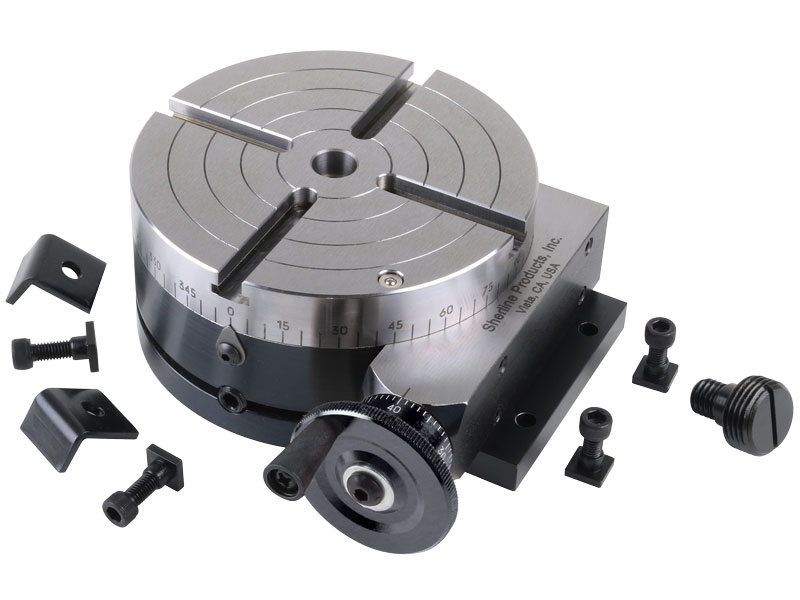
Precision 4” Rotary TableUSING THE ROTARY TABLECompiled by: Cletus L. BerkeleyISSUED: 5/30/2005 @ 8:37 AMThis is a non-profit documentThe information contained herein is presented for intellectual enrichment only and may not changehands for monetary gain. The Author, Researchers, Contributors, Manufacturers, and Suppliersassume no liability whatsoever from the use of information contained herein.
The Rotary TableWhen a rotary table is put on a vertical mill you end up with a machine that istheoretically capable of reproducing itself. This means the capabilities of your mill aregoverned by the size of the part and the ingenuity of the operator.The purpose of these instructions is to give an insight into properly using this amazingaccessory.Equipment used in this discussion:MODEL: 1810 Rotary Table, 4” PrecisionMODEL: 1811 Dividing Plate Set, 15 & 28-HoleMODEL: 1812 TailstockMODEL: 1187 Lathe Chuck, 3-Jaw 3”As sold by : littlemachineshop.comSpecificationsDiameter of Table: 100mm (4”)Center Height (Horizontal Mounting): 73mm (2.874”)Bore Taper:MT2T-Slot Width: 8mm (0.315”)Locating Key Width: 8mm and 10mm (0.315” and 0.394”)Angle of T-Slot:90-deg.Height to top of table (Vertical Mounting): 68mm (2.677”)Worm Ratio: 1:72Worm Gear Module: 1Table Circumference Graduation:360-deg.Handwheel Indication:2-minutes each divisionMin. Vernier Collar Graduation:Flatness of clamping surface: 0.0012".Parallelism of clamping surface to base: 0.0008".Squareness of clamping surface to angle face: 0.0012".10-seconds each divisionSquareness of clamping surface to center slot: 0.0012".Concentricity of center bore:0.0008" TIR.Note: STACK-ON Plastic Tool-box, a pine floor and some pine strips make the ideal storage chest forthis set.Page 2
Using a Rotary TableA rotary table can be used to machine arcs and circles. For example, the circularT-slot in the swivel base for a vise can be made using a rotary table.Rotary tables can also be used for indexing, where a workpiece must berotated an exact amount between operations. You can make gears on a millingmachine using a rotary table. Dividing plates make indexing with a rotary tableeasier.NomenclatureThe following illustrations show the various parts and controls of a rotary table andtailstock.Morse TaperCenter HoleWorm assembly position indicatorHandwheelT-SlotHorizontalMounting SlotVerticalMounting SlotDegreeIndicatorAlignmentBlocksTable Locking ClampDead CenterHeight adjustment lockDead CenteradvancementknobDead Center LockHeight Adjustment KnobTailstockPage 3
3. For all intents and purposes you are now set at 0 or 360 degrees (see photobelow).The table set at 0 or 360 degreesDisengaging the Worm DriveOn this model Rotary Table, the only way to disengage the worm drive and allow thetable to freewheel is by loosening the two worm assembly lockscrews and completelyremoving the worm assembly. The eccentric makeup of the worm assembly onlyprovides a means of “tuning- out” backlash and this is accomplished by the stepsoutlined below. It does not have enough “throw” in the clockwise direction todisengage the worm completely from the worm-gear.Eliminating Backlash in the Worm DriveNormal use of a rotary table does not require all play in the wormDrive be eliminated. If you always rotate the hand wheel in the same direction, play inthe worm drive will not affect your work.However, there are some operations where backlash can affect the work. Inthese cases, follow this procedure to minimize play in the worm drive.1. Loosen the worm assembly lock screws.2. Rotate the vernier color counterclockwise so that the index mark adjacentto the vernier is slightly to the left of the indicator on the rotary tablebody. If you move it too far, the worm drive will bind. Find the point wherethere is minimum play yet the worm drive works smoothly and free.3. Tighten the worm assembly lock screws.Note: Develop a habit of rotating the handwheel in one direction (clockwise). If you need to turn backsome, to catch a point you may have passed, turn back one full revolution of the handwheel, thenadvance clockwise, stopping at your mark. This would negate any backlash issues.Page 5
A Chuck on the Rotary TableA lathe chuck can be mounted on the rotary table to hold cylindrical objects.Lathe chuck mounted on a rotary table (mounted vertically)Chuck Adapter PlateThe chuck adapter plate supplied with the rotary table has on one side a step, turnedto mate perfectly with the Morse #2 taper of the table. This ensures perfect concentricalignment with the table. The other side is machined with another step that alignsperfectly with the model: 1187, 3-Jaw 3” Lathe Chuck. No machining is necessaryand this fixture ensures near perfect concentricity between the table and chuck. Threeshort allen bolts fasten the adapter plate to the chuck. Four allen bolts and mating T-nuts fasten the adapter plate/chuck to the table. Note: the T-nuts sometimes protrude slightlyfrom the table and may foul against the table locking nuts, slight filing of the T-nut edges may be inorder.3-Jaw ChuckMODEL: 1187 Lathe Chuck, 3-Jaw 3” is a typical self centering 3-Jaw scroll chuck.When setup on the rotary table and facing upwards, it tends to collect far more crudthan when in its normal position as mounted on a lathe spindle. Therefore, much moreattention needs to be paid to cleaning. Dry lubricants (not oil or grease) is highlyrecommended so as not to aid the collection of particulate.Using the TailstockA tailstock helps steady the job when working on relatively long cylindrical objects, youmight need to support the end of the workpiece. A tailstock provides the requiredsupport. Ensure that the deadcenter of the tailstock is in perfect coaxial alignment withthe center of the rotary table. The way I do this is by holding ½” diameter rod which Iknow to be true, in the chuck one end of the rod has been turned to a point in a lathe(like a deadcenter) I ensure that the points of the deadcenter and the rod alignperfectly. Note: The tailstock has a ramp machined into it to provide a heightadjustment when the Allen-bolt on the top is loosened and the lower adjusting knob isturned.Page 8
Rotary table set up for indexing with a tailstockSetting up the jobAn inexpensive calculator with trig functions is a must for complex jobs. Standardmilling machine set-ups usually involve aligning the work with the table and then withthe spindle. This is easily accomplished because the table can be accurately movedwith the handwheels. Aligning a part on a rotary table however, can be very tryingbecause the work has to be clamped into position. When you consider the fact that thepart turns, a .001" (.03mm) error in location gives a .002" True Indicated Run-out(T.I.R.) when checked with a dial indicator.A quick way to align the milling spindle with the rotary table is by indicating the hole inthe center of the rotary table. Next, prick punch or spot drill the center on the work youwish to have line up with the rotary table. Put a pointer in the spindle that runs true.Set the work under the spindle and lower the head until it engages with the centermark, then clamp the part down. You now have the work reasonably aligned with therotary table and spindle. At this time, rotate the table with the spindle running and thepointer slightly backed off. If the part is properly aligned, the pointer should always lineup with the center mark, and you should write down your handwheel settings. It is alsoadvisable to write an "R" or "L" after the handwheel setting to remember which waythe backlash was set. Now, if you have a DRO installed on your milling machine lifebecomes considerably easier as the center of the rotary table becomes the X0, Y0datum and coordinates can be sought directly from the display.Page 9
Maintenance & LubricationNote the lubrication points on the rotary table and inject SAE-20 using an oilcanbefore use. The worm may be lubricated with a small amount of white lithium grease.This is a sterile area, keep debris out. After use clean the rotary table of all debris andwipe with a rag soaked with oil. Store in a clean dry place.Things to NOT do:1. A Rotary table is a heavy hunk of precision crafted, cast iron,instrumentation. DO NOT DROP IT.2. Never hammer the table face or a work-piece thereon.3. Do not run the rotary table without adequate lubrication.4. Do not allow the ingress of debris into the moving parts especially theworm assembly.5. Do not store carelessly or in a damp location, it will rust.Page 10
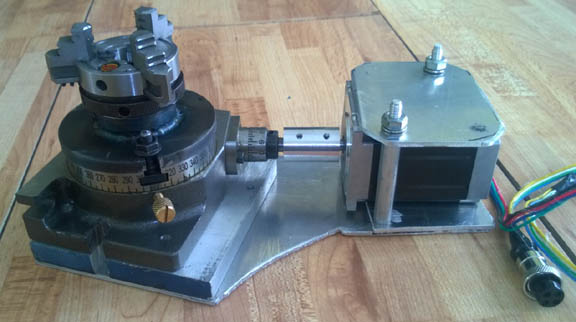
Using Dividing Plates with the Rotary TableDividing plates permit precise division of a circle into a number of divisionsor degrees. The indexing feature helps prevent errors during the repetitiveadjustments required in indexing work.Dividing plates can be used to create bolt circles, gears, polygons, and so on.These instructions are for the 4” Precision Rotary Table part number 1810 andDividing Plate Set part number 1811.Installing the Dividing PlateThe dividing plate mounts in place of the hand wheel on the rotary table.Follow these steps to mount the dividing plate.Remove the Hand Wheel1. Remove the nut and washer from the center of the hand wheel (13mm).2. Slide the hand wheel and the center indexing ring off the shaft together.This is to prevent losing the small flat spring that is between these parts.3. Loosen the setscrew and slide the inner indexing ring off the shaft.Do not lose the small key that falls out from the shaft.Note: Looking at the assembly of the handwheel and the smoothness of operation, this Rotary Tablelends itself very suitable for CNC retrofitting.Page 11
Using the Dividing PlateOnce the dividing plate is in place, the next step is to make the calculations forthe job at hand.Principle of OperationEach complete rotation of the crank moves the table 1/72 of a full rotation (5 degrees).For smaller increments there are two rings of holes on the dividing plate. The outerring has 28 equally spaced holes and the inner ring has 15 equally spaced holes.Advancing the crank using the outer ring rotates the table 1/28 of 1/72 of a rotation(0.1786 degrees). Advancing the crank using the inner ring rotates the table 1/15 of1/72 of a rotation (0.3333 degrees). By selecting the appropriate ring of holes and bycounting turns and hole advancement, a large number of equal circle divisions may beobtained. The various combinations have been tabulated in the chart below for quickreference.The sector plates help you count holes. Set them so that they include the starting andending holes for each increment of crank advancement. Then, lock the setscrew tomaintain the setting. Between table advancements, rotate the secrors to the nextposition. Make sure the indexing pin does not strike the sectors during rotation of thecrank.Calculate for DegreesIf you want to advance a certain number of degrees between divisions, here ishow to figure out how many turns of the crank handle are needed.1. Look in the Degrees column in the Indexing Table on page 8 for the numberof degrees you want to advance. If you find the value you want, read acrossthe line to find the hole circle to use, the number of full turns, and thenumber of holes beyond the last full turn. Skip the rest of this procedure.2. Divide the number of degrees per division by 5. Each full turn of the crankhandle advances the rotary table 5 degrees.3. The whole number is the number of full turns of the crank handle.4. If there is a remainder in step 1, multiply the remainder by 15.5. If the answer to step 3 is a whole number, it is the number of extra holes onthe 15-hole circle to advance the crank handle.6. If the result of step 3 is not a whole number, multiply the remainder fromstep 1 by 28.7. If the answer to step 5 is a whole number, it is the number of extra holes onthe 28-hole circle to advance the crank handle.8. If neither step 3 nor step 5 resulted in a whole number, you can’t advancethat number of degrees with this dividing plate.Page 13
Here is an example: Suppose you want to create a disk with holes that are 7.5degrees apart.So to advance 7.5 degrees, you make 1 full turn and then advance an extra 14holes in the 28-hole circle.Calculate for Number of DivisionsIf you know the number of divisions into which you want to divide a circle,follow these steps:9. Find the number of divisions you want in the Divisions column in the tableon page 8.10. Read across the line to find the hole circle to use, the number of full turns,and the number of holes beyond the last full turn.Here is an example. Suppose you want to create a circle with 48 holes. Look inthe Divisions column in the Indexing Table for 48. Here is that row from thetable.So to create 48 divisions, you make 1 full turn and then advance an extra 14holes in the 28-hole circle.Setting up the Dividing PlateOnce the calculations are done, you are ready to adjust the crank handle andsector arms.Set the Crank Handle1. Make sure that the indexing pin assembly is on the correct side of the sectorarms so it will contact a tapered edge of the sector arm.2. Loosen the nut on the indexing pin assembly.3. Move the indexing pin assembly in or out until the indexing pin fits in theholes in the appropriate hole circle.4. Tighten the nut on the indexing pin assembly.Page 14
3. Tighten the small setscrew in the outer sector ring.Operating the Rotary TableWith the dividing plate installed and set up, mount your work piece on therotary table, and the rotary table on the mill.The position of the crank handle when you start is not important as long as theindexing pin is in a hole. Make sure it is on the correct side of the sector arms,so it will contact a tapered edge of the sector arm.Each time you make a cut, you advance the work piece to the next position.Advance the Work Piece1. Pull the handle on the indexing pin assembly to disengage the indexing pin.Pull it far enough so the indexing pin clears the sector arms.2. Turn the crank handle the number of full turns required, stopping at theposition from which you started.3. Release the indexing pin partially so that the end is at the surface of thedividing plate.4. Advance the crank handle to the next sector arm. (If you need to pass thesector arms, you will need to retract the pin more to clear the sector armsagain.)5. Release the indexing pin so that it engages the correct hole.6. Rotate the two sector arms to the next starting position.Page 16
You are now ready to make your next cut. Repeat this process for eachdivision.Indexing TableThis indexing table is for a rotary table with a 72-to-1 ratio and a dividing platewith 15- and 28-hole circles.Table for a 72-to-1 ratio Rotary Table and a dividing plate with 15- and 28-holecircles.Note: It may be useful to keep a laminated copy of the following table with the dividing plate kit, orposted near the milling machine.Page 17
Cutting Gears on a rotary tableMachinery"s Handbook is one of the best sources for information on gears. Gears arebuilt to a rigid set of rules, and they are much more complex than you might at firstimagine.This explanation describes how to cut a simple, low tolerance gear (Meccano gear).You will also have to determine the blank size, depth of cut, RPM of the spindle andso on. Gears can be cut using a rotary table with a reasonable amount of precision. Inmost cases, gears, even the inexpensive ones, are very precise. Gears are usuallyproduced by "hobbing". This method uses a cutter that is similar to a worm gear. Theteeth are generated with both the cutter and the blank turning. The process is verysimilar to a running worm gear. Hobbing produces perfectly shaped teeth, that areperfectly spaced. It is theoretically possible to produce a perfect gear one tooth at atime, But be prepared to screw-up a few times before getting it right.Note: Next time I make a gear, I would dispensewith the mandrel, if at all possible and make thestepped backside of the blank longer and holdthis directly in the chuck. The tailstock would thenbe employed in steadying the blank directly at thebore. Should make for a more rigid setup.Setup for simple gear cutting (Meccano gear).Cutters can be purchased that will produce a fairly good tooth form, but they areextremely expensive and have a very limited range. A cutter can be ground that workslike a fly cutter. A 1/4" lathe tool blank fits the pictured homemade (a 9/16 boltmodifies nicely for this) tool holder. Use the damaged gear you are replacing as ashape reference to grind the tip of the cutter. At first it may seem almost impossible todo this, but it is not. Just keep checking the tool to a gear that can be used for a gaugeby holding the two up to a light source. You"ll find that the final grinding is done by"feel". Lathe tool bits are cheap and available, so it is a process worth learning. Whenthe tool is mounted in the holder, don"t allow it to stick out any more than necessary.The picture above shows a typical setup. A tailstock isn"t always necessary but in thiscase it was, and very light cutting passes were made and with a very sharp tool,Page 19
especially because of the “skinny” mandrel used. Remember, the gear blank must runabsolutely true before starting and the tool tip must be dead on centerline.Calculating Your CutsTo figure the amount to move between cuts, an electronic pocket calculator can bevery helpful. Simply divide 360° by the number of teeth you wish to cut. This will giveyou an answer in degrees and several decimal places of precision. However, thisrotary table is calibrated in degrees, minutes and seconds so some conversion isnecessary. Here’s the theory:There are several ways to measure the size of an angle. One way is to use units ofdegrees. (Radian measure is another way.)In a complete circle there are three hundred and sixty (360) degrees.An angle could have a measurement of 35.75 degrees. That is, the size of the angle inthis case would be thirty-five full degrees plus seventy-five hundredths, or threefourths, of an additional degree. Notice that here we are expressing the measurementas a decimal number. Using decimal numbers like this one can express angles to anyprecision - to hundredths of a degree, to thousandths of a degree, and so on.There is another way to state the size of an angle, one that subdivides a degree usinga system different than the decimal number example given above. The degree isdivided into sixty parts called minutes. These minutes are further divided into sixtyparts called seconds. The words minute and second used in this context have noimmediate connection to how those words are usually used as amounts of time. In a full circle there are 360 degrees. Each degree is split up into 60 parts, each part being 1/60 of a degree. Theseparts are called minutes. Each minute is split up into 60 parts, each part being 1/60 of a minute. Theseparts are called seconds.The size of an angle could be stated this way: 40 degrees, 20 minutes, 50 seconds.There are symbols that are used when stating angles using degrees, minutes, andseconds. Those symbols are show in the following table.Symbol for degree:Symbol for minute:Symbol for second:So, the angle of 40 degrees, 20 minutes, 50 seconds is usually written this way:Page 20
How could you state the above as an angle using common decimal notation? Theangle would be this many degrees, (* means times.):40 + (20 * 1/60) + (50 * 1/60 * 1/60)That is, we have 40 full degrees, 20 minutes - each 1/60 of a degree, and 50 seconds- each 1/60 of 1/60 of a degree.Work that out and you will get a decimal number of degrees. It"s 40.34722...Going the other way is a bit more difficult. Suppose we start with 40.3472 degrees.Can we express that in units of degrees, minutes, and seconds?Well, first of all there are definitely 40 degrees full degrees. That leaves 0.3472degrees.So, how many minutes is 0.3472 degrees? Well, how many times can 1/60 go into0.3472? Here"s the same question: What is 60 times 0.3472? It"s 20.832. So, thereare 20 complete minutes with 0.832 of a minute remaining.How many seconds are in the last 0.832 minutes. Well, how many times can 1/60 gointo 0.832, or what is 60 times 0.832? It"s 49.92, or almost 50 seconds.So, we"ve figured that 40.3472 degrees is almost exactly equal to 40 degrees, 20minutes, 50 seconds.(The only reason we fell a bit short of 50 seconds is that we really used a slightlysmaller angle in this second half of the calculation explanation. In the original angle,40.34722... degrees, the decimal repeats the last digit of 2 infinitely, so, the originalangle is a bit bigger than 40.3472.)Further Reading:Reading Vernier Scales: http://webphysics.davidson.edu/Applets/TaiwanUniv/ruler/vernier.htmlhttp://dl.clackamas.cc.or.us/ch104-01b/vernier.htmFootnoteThis manual started out as my shop notes for my newly acquired Rotary Table, as Ibegan trying to understand it’s setup, I found that there’s precious little informationrelating to the setup and use of the device. I tried to cram as much information intothese few pages so as to give a well rounded perspective on the setup and use of aRotary Table System. As with machining in general, proficiency comes with practice.Be patient, it is not uncommon for >85% of the time taken to do a machining job, to bespent in setting up. Measure twice and cut once! …as it’s easier to remove metal thatto put it back on.Thanks to Susan (my wife) for a really neat birthday gift.Have fun and be safe,CletusCletus Berkeley is in no way affiliated with Littlemachineshop.com…. just a another satisfied customer.Page 21
In recent years, rotary tables have become widely used in machine tools. In particular, the rotary tables are frequently used to perform indexing operations, and the reliability of the indexing operations and clamping mechanisms is an important element of the rotary tables.
In general, an irreversible worm gear mechanism is used as a rotating mechanism of a rotary table (see, for example, Japanese Patent Application Laid-Open No. 2002-18678). Since the worm gear mechanism of this type is constructed so that a worm and a worm wheel mesh with each other, it is subject to backlash, though very small. Even when the table is stationary, therefore, looseness corresponding to the amount of the backlash is caused, so that an indexed angle of the table may be deviated to adversely affect the machining accuracy of a workpiece held on the table.
In order to solve the above problem, there are provided a brake disk, which is rotated together with a spindle for transmitting rotary motion from a rotary drive unit to the table, and a piston capable of holding the brake disk in conjunction with a cylinder. An air pressure is applied to the piston to hold the brake disk between the piston and the cylinder. The motion of the spindle that connects with the brake disk is restricted by a frictional force generated between the brake disk and a fixing member, whereby the rotary table connecting with the spindle is kept standstill state (see, for example, Japanese Patent Application Laid-Open No. 2012-202484).
A clamping mechanism of the rotary table requires a high clamping torque to cope with heavy cutting and heavy loads. In the conventional rotary table, the clamping torque is produced by using a single brake disk, so that its magnitude is insufficient. Further, there is no existing means for easily increasing the clamping torque in the case where a high clamping torque is required after the rotary table is installed by a user.
Accordingly, in view of the prior art problems described above, the object of the present invention is to provide a rotary table capable of providing a high clamping torque and a clamping mechanism of the rotary table.
A rotary table according to the present invention comprises a rotating shaft rotatably disposed in a casing and a clamping mechanism configured to disable the rotating shaft from rotating. The clamping mechanism comprises a first clamping mechanism and one or more second clamping mechanisms. The first clamping mechanism comprises a first cylinder secured or removably disposed in the casing, a first piston provided in a first space section defined in the first cylinder and configured to reciprocate in the first space section as a working fluid is delivered to or from the first space section, and a first brake disk configured to engage the first piston, thereby disabling the rotating shaft from rotating. On the other hand, the at least one second clamping mechanism comprises a second cylinder removably disposed relative to the first cylinder, a second piston provided in a second space section defined in the second cylinder and configured to reciprocate in the second space section as the working fluid is delivered to or from the second space section, and a second brake disk configured to engage the second piston, thereby disabling the rotating shaft from rotating.
Further, a clamping mechanism according to the present invention is configured to be mounted in a multistage arrangement on a rotary table in order to disable a rotating shaft rotatably disposed in a casing from rotating and comprises a cylinder, a piston provided in a space section defined in the cylinder and configured to reciprocate in the space section as a working fluid is delivered to or from the space section, and a brake disk configured to engage the piston, thereby disabling the rotating shaft from rotating.
According to the present invention, there can be provided a rotary table capable of providing a high clamping torque and a clamping mechanism of the rotary table.
One embodiment of the present invention will now be described with reference to the accompanying drawings. In the rotary table according to the present embodiment, a motor for driving a rotating shaft is installed in a casing. However, the rotary table according to the present invention is not limited to the configuration in which the motor is disposed in the casing. For example, it may alternatively be a rotary table in which a motor is disposed outside a casing, as described in Japanese Patent Application Laid-Open No. 2002-18678 mentioned before, or a rotary table which includes no motor as a constituent element and in which a jig plate is supported for rotation, as described in Japanese Patent Application Laid-Open No. 2013-144321 mentioned before.
FIG. 1 is a sectional view showing a basic structure of the rotary table. FIG. 2 is a sectional view of one embodiment of the rotary table according to the present invention.
As shown in FIG. 1, a shaft 2 of the rotary table is rotatably supported by a main bearing 3aand a support bearing 3bin a casing 1. A stator 4b, cylinder 9a, sensor head 5b, and lid 8 are secured to the casing 1. On the other hand, a rotor 4aof the motor, sensor gear 5a, and disk 6aare all secured to the shaft 2 for integral rotation with the rotary table.
A piston 7ais provided having an advance/retreat stroke in the cylinder 9a. An advancing air chamber 9fand a retreating air chamber 9gare provided between the piston 7aand the cylinder 9asuch that the piston 7acan be moved to the clamp side by compressed air.
In a clamped state, in contrast, the moment the retreating air chamber 9gis evacuated, compressed air is delivered to the advancing air chamber 9f. Thereupon, the piston 7ais advanced so that the disk 6ais held between a friction surface 8aon the lid 8.
The rotary table shown in FIG. 2 has a structure in which another clamping mechanism 11 is added to the rotary table of the basic structure as shown in FIG. 1. Such an additional clamping mechanism 11 can be attached to the clamping mechanism 11 in a manner such that they are superposed in an axial direction of the rotating shaft. Moreover, still another clamping mechanism of the same structure as the additional clamping mechanism 11 can further be attached to the additional clamping mechanism 11 (FIG. 2) in a manner such that they are superposed in an axial direction of the rotating shaft.
In the rotary table of the basic structure shown in FIG. 1, the lid 8 is removed, the additional clamping mechanism 11 is mounted in place, and the removed lid 8 is then attached to the clamping mechanism 11. A connecting cylinder 9bis secured to the cylinder 9aby bolts (not shown in FIG. 2). Further, an additional disk 6bis secured to the shaft 2 for integral rotation with the rotary table.
In the clamped state, the piston 7aand the additional piston 7bare pressed against clamping surfaces that are opposed individually to the disk 6aand the additional disk 6bin the clamping mechanisms, and a clamping force is obtained using frictional forces on the respective contact surfaces. Since the rotary table shown in FIG. 2 comprises two clamping mechanisms, it can produce a clamping torque twice that of a rotary table with a single clamping mechanism. If a higher clamping force is required, clamping mechanisms of a number corresponding to a required increase in magnitude of the clamping torque should only be added, to the existing ones with the lid 8 removed.
According to the present invention, a plurality of clamping mechanisms are added to an original rotary table. In this arrangement, the clamping torque is obtained using the frictional forces on the contact surfaces by pressing the disks against the clamping surfaces opposed to the disks in the individual clamping mechanisms. Therefore, a high clamping torque can be produced taking advantage of the addition of the braking effect of the frictional forces. If the clamping torque is expected to be increased after the rotary table is installed, moreover, it can be achieved by simply providing additional clamping mechanisms in the field. Further, there can be provided a structure that can easily provide a high clamping torque at a site such as a factory where the machine tool is used after the rotary table is installed in the machine tool.
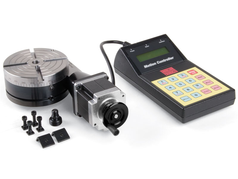
Sherline has taken their accurate and reliable 4″ rotary table into the 21st century with the addition of Computer Numeric Control. Clock-makers or anyone with a need to cut gears or other complicated radially symmetrical patterns will find this accessory takes all the headaches out of repetitive indexing operations.
The rotary table comes with clamps and T-nuts for attaching it to the T-slots of a Sherline mill table. In addition, there are two options available for mounting the table in the vertical position or at other angles:
Right-Angle Attachment—This plate holds the table in the vertical position with a center height of 2.7″. A right-angle tailstock is also available to support long stock held on center in the rotary table.
Tilting-Angle Table—This table holds the rotary table and can be fixed at any angle from 0° to 90°. In the 90° position, the rotary table center is also at the 2.7″ height, which allows the right-angle tailstock to be used with it.
After entering the number of steps per revolution (or the number of degrees per step) on a simple numeric keypad, the table advances quickly and precisely to the next position at the touch of a single advance key. If an error is made, previous positions can be accurately recalled by hitting another button. Basic resolution is 28,800 steps per revolution, ±0.006° per step. This allows the accurate machining of items like gears with odd numbers of teeth. Computations are made internally to a high degree of accuracy to avoid cumulative errors.
The A-688 direct drive rotary table with air bearings provides extremely high resolution and geometric performance. The angular resolution of this high precision air bearing spindle is 0.0015µrad (0.00003 arcsec), and flatness and eccentricity are specified better than 175nm and 300nm, respectively. This is made possible by high resolution, absolute measuring feedback encoders, and low-cogging frameless and slotless torque motors. The A-688 rotary table can be used in any orientation. Air bearing spindles guarantee a virtually unlimited service life with no wear, and zero required maintenance. As with all PI air bearings tables, the A-688 spindle is clean room compatible and requires no lubrication.
PI uses EtherCat based, high performance motion controllers ideally suited for closed-loop control of the rotation tables. Advanced algorithms are available to deal with changing load conditions and to suppress external disturbances.

Rotation tables with air bearings are used when rotary motion with the highest accuracy, smoothness, and geometric performance is required. Due to the lack of friction, these high precision rotation bearings and direct-drive motorized rotary tables can achieve angular resolution in the sub-microradian range. PI’s air bearing design and manufacturing group provides hundreds of man years of design experience along with the manufacturing and test equipment to produce high quality rotary tables with the tightest tolerances.
Rotary air bearings (air bearing spindles) are friction free, and all of PI’s motorized air bearing rotation stages employ closed-loop, non-contact 3-phase direct-drive torque motors, and optical high-resolution rotary encoders for ultra-reliable maintenance-free operation with basically unlimited service life.
Absolute angle-measuring feedback sensors are available to provide closed-loop control with single digit microradian bi-directional repeatability. Direct-drive rotary air bearing tables also provide better eccentricity, flatness, and minimized wobble compared to rotary stages based on mechanical bearings. The friction-free design allows for high angular velocity without vibrations and noise.
Applications of rotary air bearing spindles / motorized direct-drive rotary tables include indexing, metrology, optical lens testing, bio-medical engineering, runout measurements of machined parts, and fiber optics.
PI’s high-performance closed loop servo motor controllers are available to precisely control position, acceleration and velocity, with advanced algorithms. Fully integrated multi-axis motion systems with linear air bearing stages and combinations with gantry systems are also available from PI’s air bearing division.
Boasting a 1300 mm footprint, the TO1300 suddenly makes larger scale applications possible that previously seemed out of reach− as current direct-drive tables are relatively small and limited to a diameter of 750 mm. Additionally the TO1300’s high-tech drive operates predominantly without mechanics or gearboxes.
For challenging tasks of this nature, a mechanical heavy duty table is typically the logical choice. Due to their gearing ratio, however, these tables don’t fare well in service life calculations for use at such high speeds as the needle bearings simply suffer from too much wear.
The correct alternative is a direct drive; which inspired the development of the TO1300. With a direct drive, only one bearing is under load which is virtually free of backlash. The table is low-wear and easily capable of delivering the desired dynamic performance requirements.
Unique to the TO1300 is that customers can customize it to their individual requirements. For example; they can make a modular selection between bearings, encoder and motor, and thereby alter the following table characteristics:
A specialist in automation, WEISS also offers many sizes for the TO series direct-drive rotary indexing tables; ranging from small to very large. Optimal solutions for specific application challenges can be achieved from the series wide range of options. Each TO model is also available in a version with a cleanroom certificate.
Corporate Profile: An integral part of the Weiss global network, Weiss North America (ISO-9001 Certified) leverages over 45 years of reliable world-wide expertise to comprise an integrative, customer-specific approach to its vast array of electromechanical products. Our 100% vertical range of manufacturing ranges from rotary indexing tables, handling systems, and linear assembly systems−providing flexible technology for turnkey solutions that incorporate electronics, mechanical systems, software, and comprehensive engineering support. This enables us to provide pre-installed, intelligent, and highly convenient solutions for the entire field of kinematics.


 8613371530291