
ag davis rotary table free sample

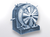
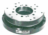
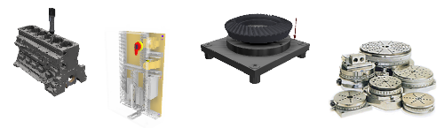
The ULTRARON is a precision-engineered rotary table, produced entirely at A.G. Davis - AA Gage, with applications for inspection, tool room and/or production machining. The ULTRARON"s accuracy is made possible by the use of precision lapped balls and integral ground races. The ULTRARON has a standard concentricity accuracy of 30 millionths T.I.R. (0.000030) and a wobble or rotating parallelism is held within 100 millionths (0.0001) on sizes to 24" in diameter.
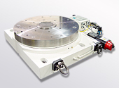
The A.G. Davis - AA Gage Precision Broach Rotary Tables are high precision rotary systems manufactured for precision broaching applications. The Broach Rotary Tables can be supplied with stand-alone or rack-mounted controller, or can be interfaced to your operational Rotary Axis Control.
With nearly 50 years in the science of metrology, our engineering staff understands the quality control problems inherent in the developement of new products and processes. Where problems cannot be solved by our standard production gages, we are prepared to design and build custom gaging. Challenge us with your gaging requirements.
Design & mfg of ultra-precision rotary motion systems to test & calibrate exacting applications. Design & mfg of precision gaging systems manual & fully automatic. Also a line of Hydra-Grip workholders - arbors and chucks. Ultradex, Ultraron, SPC Software
accelerometers, absolute, acceptance, accuracy, air,bearings, alignment, analog, angle,measurements, angularity, apply, arbors, artifact, attribute, audit, autodex, automaticm, axis, bar, bearing, best-fit, bizillionths, bore, broaching, calibrate, calibration, chamfer. checkmate, , chucks, circularity, column, comparison, compensation, con-ax, concentricity, contouring, controls, couplings, custom , cylindricity, dedicated, depth, depth, gage, diagnostic, dial, diameter, digital, circle divider, roto-con, dimensional, disc, display, digasine, eccentricity, electronic,encoder,inspection, fail, feeler, final-inspection, fit, fixture, flatness, flexible, flush,pin, form, function,functional, gage-maker, gases, geometric, go, g-no,go, grip, groove, guidance, gyroscope, hand,height, hirth, hole, hydra-grip, i.d., indicating, indicator, inertial,navigation, index, indexer, indicator, in-line, in-process, inside, inspection, lay-on, layout, length, limit, linear, machining, master, manudex, measurement, measurement devices, metric, metrology, micron, milling, minimum-maximum, miss-alignment, multiple, multi-axis systems, no-go, o.d., off-line, omni, on-line, outside, parallelism, pass, perpendicularity, plug polygons, position, precision, production, profile, program, quality, rate,tables, readout, reject, relation, resolver,testing, ring, roil-chek, rotary, roundness, runout, servo,systems, sight, size, snap, software, spc, special,delivery, squareness, station, straightness, star-tracker, sweep, tables, teeth, template, test, test,stands, thread, tolerance, true position, ultrachucks,ultradex, ultraron, ultra-ro-dex, variable, width, workholding,
precision rotary index tables, gages, gage components, fixture gaging, work holding and automatic gaging systems - a. g. davis / aa gage in michigan.
www.machinedesign.com is using a security service for protection against online attacks. An action has triggered the service and blocked your request.
Please try again in a few minutes. If the issue persist, please contact the site owner for further assistance. Reference ID IP Address Date and Time 20ed59e0f57c4a558f474ac5bb94baa0 63.210.148.230 02/02/2023 05:02 PM UTC
Rotary index tables in the form of turning of dividing tables on machine tools have hitherto been employed for establishing and measuring predetermined angular distances, cam tracks and the like.
Turning tables have the advantage that they can be fixed in any desired angular position. However, the brake means which such turning tables are provided with for maintaining the table in a stationary position cannot guarantee absolutely reliable securement of the table in the presence of strong displacement forces.
Dividing tables offer the advantage of being provided with Hirth-type serrations and are therefore able to resist even great displacement forces. On the other hand, dividing tables can only be fixed in predetermined angular positions corresponding to a multiple of the pitch of the Hirth-type serration.
In view of the disadvantages that have to be tolerated in both known table constructions, successive machining of workpieces on the two known types of rotary index tables is often unavoidable in manufacturing technology.
Accordingly, the object underlying the invention was to produce a rotary index table which unites the advantages of the known turning and dividing tables within itself and can therefore be universally employed on machine tools both as a turning and dividing table.
The object underlying the invention is attained by a rotary index table of the type described at the beginning in accordance with German Published patent application No. 1,962,097.
If, for example, predetermined angular distances corresponding to a multiple of the tooth pitch of the Hirth-type serrations are to be established on the rotary index table according to the invention, the table plate can be secured in position on the table housing by the Hirth-type serrations.
If, on the other hand, the table plate is to be rotated through angles which cannot be set by the Hirth-type serrations on the basis of their pitch, the table plate can be secured in position on the table housing by the brake means, once it has been adjusted to the respective angular position. Thus, the table plate can also be secured in any angular position.
It is advisable to electronically control the drive means for adjustment of the table plate through both predetermined turning angles which can be established by the tooth pitch of the Hirth-type serrations and turning angles of any size, so that the angular positions of the table plate that are to be selected successively can be programmed in the controls of the respective machine in advance and then automatically performed.
Electronic control of the drive means for determining measurement values corresponding to angular positions to be selected can be effected by a direct electronic measurement system (rotary inductosyn system) or advantageously by an indirect measurement system (resolver measurement).
The rotary index table according to the invention offers the following adjustment possibilities, assuming that the Hirth-type serrations have a tooth pitch of one degree. In this case, the table plate can be secured in 360 positions with the aid of the Hirth-type serrations. Used as a turning table with a direct and/or indirect electronic measurement system for controlling the drive means, the table plate can in accordance with the resolver power of the measurement system and the electronic machine controls be adjusted to, for instance, 360,000 positions. If, on the other hand, the Hirth-type serrations have a pitch of 0.5°, the table plate can be adjusted to 720 positions with the aid of the Hirth-type serrations.
If the rotary index table is used as a dividing table, raising of the table plate from the table housing so as to disengage the Hirth-type serrations for indexing the table plate can be avoided. In this case, it is expedient for the adjustment member for raising and lowering the carrier plate to be in the form of an adjustable wedge which can cooperate suitably with a guide shaft that is guided in the table housing and carries the carrier plate. The construction disclosed constitutes a preferred embodiment of the invention which enables positive guidance of the carrier plate in both of its directions of movement. The toothed ring provided therein enables, in addition to a favorable arrangement of a Hirth-type serration on the table plate, an advantageous drive connection between the table plate and the drive means, if, the toothed ring comprises at its circumference a ring gear which meshes with a drive wheel of the drive means. The ring gear and the drive wheel can be in the form of spur gears which mesh with one another, and the brake means must be designed such that it enables either a decrease in the flank play or absolutely reliable securement of the table plate relative to the table housing, depending on how the rotary index table is to be used.
By the simple structural measure disclosed, the flank play can be reduced and the toothed ring detained, respectively. If, for example, the table plate is to be driven for milling cam tracks, the flank play can be reduced to an advantageous value in the manner disclosed. On the other hand, the flank play can be correspondingly enlarged at short notice if the table plate is to be operated at rapid traverse rate. Finally, the tooth flanks can be brought together under pressure in order to secure the table plate.
In a preferred embodiment of the invention, the drive means and the brake means constitute one component, as disclosed, which is designed such that the drive wheel of the drive means which meshes with the ring gear of the toothed ring on the table plate constitutes at the same time the brake member for securing the ring gear and the table plate, respectively.
A construction which distinguishes itself by way of particular structural simplicity and functional reliability can be obtained by having the ring gear of the toothed ring take the form of a worm gear which meshes with a drive worm of the drive and brake means, said drive worm being adapted to be radially displaced by the brake means in the direction of the worm gear so as to secure the worm gear and the table plate, respectively, and to engage with the flanks of the worm gear under pressure. In this way, any play between the tooth flanks of the worm gear and the threads of the drive worm is eliminated, and the table plate is thereby locked to the table housing in an absolutely reliable manner, provided that the drive worm is free of play in both axial directions. The subject matter of the invention constitutes further advantageous embodiments of the drive and brake means in the form of one component.
Further features and details of the invention are apparent from the following description of a preferred embodiment of a rotary index table according to the invention, as illustrated in the drawings, and also from the patent claims.
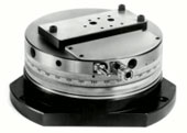
FIG. 1 is a shortened side view and partially a longitudinal cross-sectional view of the rotary index table, wherein the table plate and the table housing are coupled to each other by positively held interlocking Hirth-type serrations.
The rotary index table illustrated in FIG. 1 comprises a stationary table housing designated in toto 10, with a table plate 12 rotatable relative to said table housing mounted thereon. The table plate comprises a toothed ring 14 secured to the center of its bottom face for the purpose of mounting it on the table housing. The toothed ring rests with an outer flange 16, for example, on two flat slide rings 18, 20 consisting of a suitable plastics material and arranged concentrically on the top face of the table housing, and is, therefore, supported in an axial direction. In a radial direction, this toothed ring is preferably rotatably mounted with the aid of a radial ball bearing 22 on a central upwardly extending shaft portion 24 of the table housing. In order to drive the table plate 12 and the toothed ring 14, respectively, the toothed ring 14 comprises on its outer circumference a ring gear which preferably constitutes a worm gear 26. A drive worm 28 meshes with the latter.
As illustrated in FIG. 1, a first Hirth-type serration 30 is integral with the top face of the toothed ring 14. A second Hirth-type serration 32, which is concentric with and located in the same plane as the first Hirth-type serration 30, is integral with the top face of a coupling ring 34 which is, for example, rigidly connected by screws and pins to the table housing 10 on the top face of the shaft portion 24 of the table housing 10. 36 designates a disc-shaped carrier plate which is located in a space 38 provided between the table housing 10 and the table plate 12. This carrier plate 36 comprises on its underside a cylindrical guide shaft 40 which is axially displaceable, but substantially non-rotatably guided in an axial cylindrical recess 42 in the shaft portion 24 of the table housing.
The carrier plate 36 overlaps with its edge the two Hirth-type serrations 30 of the toothed ring 14 and 32 of the coupling ring 34 and comprises on its face directed towards these Hirth-type serrations a third Hirth-type serration 44 which toothing bridges the first and second Hirth-type serrations and which toothing ridges lie in a common transverse plane perpendicular to the axis of the table plate.
For axial adjustment of the carrier plate accommodating the third Hirth-type serration 44, there is provided, for example, an adjustment member designated in toto 46 which is disposed in the table housing 10 for adjustment perpendicular to the direction of adjustment of the cylindrical guide shaft 40 and is actuatable by a suitable actuation device.
As shown in FIG. 2, the adjustment member 46 comprises at its front end 48 a top wedge surface 52 and a bottom wedge surface 54 parallel to the former, which extends in the direction of motion of the adjustment member and, as viewed in FIG. 2, are downwardly inclined in the direction of the face of the front end 48. Two cylindrical bolts 56, 58 are arranged in the recess 50 of the cylindrical guide shaft 40 so as to extend through the recess in a transverse direction. The upper bolt 56 touches the top wedge surface 52 along a circumferential line while the lower bolt 58 comprises at its circumference a transverse groove whose groove bottom 60 rests against the bottom wedge surface 54.
When the adjustment member as illustrated in FIG. 2 is moved to the right by pressure medium actuation, the cylindrical guide shaft 40 is thereby directed upwardly and the third Hirth-type serration 44 on the carrier plate 36 is disengaged. In this case, the table plate 12 can be turned about its axis via the drive worm 28 through worm gear 26 to the toothed ring 14 in order to carry out a readjustment.
When the adjustment member 46 as shown in FIG. 2 is moved to the left, which can be effected, for example, by a pressure spring 62, the carrier plate 36 is thereby lowered and its Hirth-type serration 44 engages again in a positively held manner with the two other Hirth-type serrations 30, 32.
The toothed ring 14 which is firmly connected to the table plate 12 by means of bolts 96 is thereby coupled with the coupling ring 34 through toothed serrations 30, 44 and 32 locked to the table housing 10. The table plate 12 is thus fixed relative to the table housing 10 in an angular position established by the pitch of the Hirth-type serrations.
In accordance with the invention, a brake means is associated with the table plate 12. This brake means enables the table plate 12 to be fixed in any angular position relative to the table housing 10 when the carrier plate 36 is in the raised position, and the table plate 12 is disengaged from the table housing 10, respectively.
The drive worm 28 is disposed on the front end of a drive shaft 68 mounted in a bearing sleeve 66 for rotation with said drive shaft. The drive shaft is mounted in the bearing sleeve so as to be capable of receiving both radially and axially directed forces without play. The bearing sleeve 66 extends through a receiving bore 70 in the table housing 10 with radial play and is secured at its rear end in a receiving member 72. The latter consists of two coaxial portions 74,76 which, as shown in FIG. 4, can, for example, be of square peripheral configuration, said portion 76 being secured to the table housing 10 by attachment screws 79, and said portion 74 being flexibly connected to said portion 76.
For this purpose, the receiving body 72 comprises slits 78 and 80 extending from the top and the bottom in a common plane and ending at a distance a from each other (see FIG. 4). The inside area of both slits is extended by a bore 82, 84, respectively. These slits and a central bore 86 through which the bearing sleeve 66 extends, form two laterally spaced connection links 85, 87, which, as shown in FIG. 3, are located in a plane perpendicular to the drawing plane, with their transverse center line located in a plane tangential to the pitch circle 88 of the worm gear 26. These links 85, 87 thus define a swivel axis about which the bearing sleeve is radially deflectable together with the drive shaft 68 and the drive worm 28 in the direction of the worm gear.
The drive means which drives the drive worm 28 is controllable by an electronic measurement system, more particularly, an indirect measurement system (resolver measurement) so that the table plate 12 can be successively adjusted to predetermined angular positions.
If it is intended to employ the rotary index table as dividing table, the angular positions of the table plate are determined by the tooth pitch of the Hirth-type serrations 30, 32, 44. If, on the other hand, the rotary index table is to be set at angular positions that deviate from a multiple of the pitch of the Hirth-type serrations, the carrier plate 36 is not to be lowered, and the Hirth-type serrations 30, 32 are not to be coupled, once the desired angular position has been attained, but rather the worm gear 26 and thus the toothed ring 14 and the table plate 12 are to be fixed relative to the table housing 10 by the brake means. To this end, the bearing sleeve 66 is deflected in the direction of the worm gear 26 by the actuation rod 94 of the brake means, which is enabled by the mutual flexible connection of the two portions 74, 76 of the receiving member 72 by the links 85, 87. The flanks of the worm threads of the drive worm 28 are thereby urged against the tooth flanks of the worm gear 26 under pressure, which results in engagement of the worm gear 26 and the drive worm 28 without play. This prevents the worm gear 26 and thus the table plate 12 from turning about the axis of rotation. In this way, it is possible to employ the rotary index table as a turning table whose table plate can be fixed in any angular position on the table housing.

Weed control in vineyards enhances the establishment of newly planted vines and improves the growth and yield of established vines. Growers have many weed management tools available to achieve these objectives, but the method in which these tools are utilized vary from year to year and from vineyard to vineyard.
Weed management is an integral part of an overall vineyard management system. Plants on the vineyard floor influence the presence of other pests such as vertebrates, insects, mites, nematodes, and diseases. A weed management program should start before new vines are planted. The more difficult-to-control weeds (particularly perennials) are easier to manage before vines are planted. Weeds reduce vine growth and yield by competing for water, nutrients, and sunlight. Competition from weeds is most severe during the first few years after planting in areas where vine root growth is limited due to shallow or compacted soil. Weeds growing around the trunk compete directly with vine growth and provide a good habitat for field mice or voles, which can girdle and kill young vines. Gophers are most often found in nontilled vineyards and are common where broadleaf weeds, such as field bindweed and perennial clovers, predominate. These subterranean animals feed on the roots and can weaken or kill young vines. Additionally, weeds that have dried out can become a serious fire hazard
Integrated weed management practices vary considerably from vineyard to vineyard. Location in the state, climatic conditions, soils, weed species present, age of vines, irrigation practices, topography, and grower preferences significantly influence vineyard floor management decisions and the techniques and tools used.
Soil characteristics play an important role in weed management. Soil texture and organic matter influence the composition of weed species present, the number and timing of cultivations required, and the activity and residual effects of herbicides applied. Sandy loam soils usually dry more quickly than clay soils and may require more frequent cultivation to achieve effective weed control. On light-textured soils, annual species, such as puncturevine, crabgrass, horseweed, and Panicum spp., and perennial weeds, such as johnsongrass, nutsedge, and bermudagrass, are more prevalent. On heavier-textured soils, perennials such as curly dock, field bindweed, and dallisgrass are commonly found. Many herbicide labels recommend using low rates of the product on soils considered high in sand or low in organic matter, in order to reduce the potential for vine injury as herbicides can move deeper in the profile. A second, or split application, may be necessary.
Herbicides are traditionally discussed as belonging to two groups: those that are active against germinating weed seeds (preemergence herbicides) and those active on growing plants (postemergence herbicides). Some herbicides have pre- and postemergence activity. Herbicides vary in their ability to control different weed species. In most vineyards, herbicides are only used on a narrow strip centered on the vineyard row that comprises 15 to 30% of the total vineyard area. Check the SUSCEPTIBILITY OF WEEDS TO HERBICIDE CONTROL tables and consult product labels for specific weed control activity.
Preemergence herbicides are active in the soil against germinating weed seedlings. These herbicides are applied to bare soil and then moved into the soil with rain or irrigation where they affect germinating weed seeds. However, some herbicides like trifluralin, require mechanical incorporation. If herbicides remain on the soil surface without being activated within a reasonable amount of time through rain, irrigation, or mechanical incorporation, some will degrade rapidly from exposure to sunlight, resulting in reduced weed control. Large weed seeds, such as wild oat, may germinate in the soil below the herbicide zone and will not be controlled by a treatment.
Application equipment must be accurately calibrated to apply the proper amount of carrier and herbicide to the soil and young growing weeds. For safe application and to minimize drift, spray equipment should be equipped with a short boom that has nozzles designed to minimize the amount of very small spray particles generated. Avoid spray nozzles and spray pressures that produce spray droplets less than 200 microns in size (very fine and fine-sized droplets) as these tend to drift more. Nozzle technology has advanced significantly in recent years and all major nozzle manufacturers have developed one or more nozzles that will minimize drift. Check your nozzle catalog or the internet. Off center (OC) nozzles are often used alone or on the end of the boom to direct herbicide applications toward the center of the row. Some herbicides require special use precautions as indicated in the table below. Always read and follow the entire product label before using any pesticide.
Fish consumption advisories are in effect at the Nebraska lakes and stream segments listed on the table below. Samples are collected by the Nebraska Departmentof Environment and Energy, analyzed by the U.S. Environmental Protection Agency and advisories are issued by the Nebraska Department of Health and Human Services. A more detailed explanation of the sampling program can be found in the document, “Regional Ambient Fish Tissue Program: 2020 Assessment Report.”
The advisories listed below are not a ban on eating fish, but it is suggested that the public limit long-term consumption of fish caught from those specific waterbodies to eight ounces per week (for adults). These advisories are based on sampling taken through 2020. The table below lists the waterbody advisories by county and the contaminants of primary concern. Many compounds were analyzed in the samples, but only the primary ones listed led to consumption advisories.
*The “Fish Species” listed on the table denotes the type of fish that were analyzed from that waterbody. Although advisories are issued only for the species analyzed, it should be noted that other species of fish inhabiting the same waterbody may bioaccumulate similar levels of contaminants. However, these levels can vary depending on the type of fish. For example, mercury tends to bioaccumulate to a greater extent in larger predator fish, such as largemouth bass, and is typically lower in smaller fish and species such as bluegill and crappie. For more information, refer to the DHHS brochure,“Eat Safe Fish in Nebraska”*
Additional linksFor more information about the chemicals of primary concern and health risks, see Nebraska Department of Health and Human Services’Environmental Risk Assessment*web page.TheNebraska Fishing Guide*provides information you need to fish Nebraska water, including: regulations; seasons; limits; special area regulations; public waters guide; stocking reports; outdoor reports; a fish identification guide; Master Angler Awards; photos; discussion forum; and the ability to purchase a permit online. The URL is:http://outdoornebraska.gov/fishingguidesandreports/*

The page you are looking for no longer exists. Perhaps you can return back to the homepage and see if you can find what you are looking for. Or, you can try finding it by using the search form below.


 8613371530291