
ag davis rotary table price
The ULTRARON is a precision-engineered rotary table, produced entirely at A.G. Davis - AA Gage, with applications for inspection, tool room and/or production machining. The ULTRARON"s accuracy is made possible by the use of precision lapped balls and integral ground races. The ULTRARON has a standard concentricity accuracy of 30 millionths T.I.R. (0.000030) and a wobble or rotating parallelism is held within 100 millionths (0.0001) on sizes to 24" in diameter.
The A.G. Davis - AA Gage Precision Broach Rotary Tables are high precision rotary systems manufactured for precision broaching applications. The Broach Rotary Tables can be supplied with stand-alone or rack-mounted controller, or can be interfaced to your operational Rotary Axis Control.

A. G. Davis - AA Gage has been the industry leader in providing the design and manufacture for precision gages of all types, from small attribute (go/no go) gages, variable (data) gages, standard gages and components, to transfer line, gantry loaded semi-automatic and fully automatic inspection machines.

The Precision Rotary Tables are designed for use in Metrology, Inspection, and other precision applications. The Rotary Tables can be supplied with stand-alone or rack-mounted controllers, or can be interfaced to your operational Rotary Axis Control. The control is a solid-state, closed-loop system incorporating the latest State-of-the-Art concepts and can include IEEE or RS232 interface for remote program control.
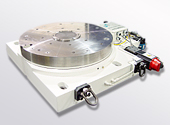
The Air Float Rotary Table consists of hardened steel faceplate, which is floated on air in the thrust plane and centered by preload ball bearings radially during rotation. After an index move is completed the Air float is shut off allowing the faceplate to rest on the base of the rotary table producing excellent wobble characteristics. This action also friction locks the Air Float Rotary Table. A high-grade meehanite base casting is used to support the faceplate. Standard faceplate mounting pattern is by threaded hole patterns with other configurations available. The Air Float Type Precision Rotary Table can only be used with the faceplate in the horizontal plane.
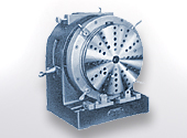
The Ball Bearing Rotary Table consists of hardened steel faceplate supported by a maximum diameter preloaded angular contact ball bearing. The large diameter ball bearing produces excellent wobble characteristics. The preloaded ball bearing along with the closed loop servo system provides for continuous as well as point-to-point measuring. A high-grade meehanite base casting is used to support the ball bearing. Standard faceplate mounting pattern is by threaded hole patterns with other configurations available.
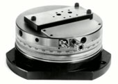
The Air Bearing Rotary Table consists of hardened and stabilized stainless steels and/or high-grade steels with corrosion resistant coatings. The base is made from high-grade meehanite castings. The Rotary Table employs a fully trapped gas bearing for both radial and thrust planes. The gas bearing jets are manufactured of precision machined gemstones. The air bearing along with the closed loop servo system provides for continuous as well as point to point measuring. Standard faceplate piece part hold down consists of threaded hole patterns, or special configurations are optionally available.
Air bearings require small clearances between rotating members. The possibility of these surfaces contacting each other during rotation is a major concern of air bearing users. Typically when this touch down does occur conventional air bearings will seize up and require major repairs. A.G. Davis-AA Gage has eliminated this possibility. The air orifice manifold detail is constructed from hardened stainless steel. The opposing surfaces are constructed from high-grade hardened steel and coated with a proprietary material. This construction permits the air bearing to lose air pressure while rotating even under maximum rated load and not damage the air bearing thrust and radial precision surfaces. After the air pressure is reinstated the bearing will freely operate as before.
The servo drive utilizes a capstan type friction wheel drive system. This drive system eliminates backlash (lost motion) between the servo motor and the Rotary Table it must position. The zero backlash condition provides an excellent foundation for a servo system which positions accurately without instability over a wide range of payload conditions.
The drive is constructed to eliminate any side loading of the rotary table bearings. Tangential loading only. This is accomplished by mounting the entire capstan drive package on a pivot which is tangent to the table drive rim. The main capstan drives on the O.D. of the drive rim while an opposing wheel bearing runs on the I.D. of the drive rim. The drive force required to engage the main capstan is provided by the opposing wheel bearing which creates a pinching action on the drive rim. This pinching action along with the pivot allow the drive to follow the drive rim"s motion without imparting any force to the rotary tables precision bearings. Note -unwanted side loading of the rotary table bearing will cause an increase
The base of the rotary table can be provided with air jet pads. These pads when actuated allow the rotary table to float on a level continuous flat surface. This feature is particularly convenient to CMM users who often move the rotary table to other locations on the CMM for various applications. The Air Ride is actuated by a dead man switch (automatically turns off when released). The switch is located adjacent to the drive cover.
A micro switch can be provided to close approximately 10° to 15° before the encoder"s marker pulse. The approach direction can be either clockwise or counterclockwise. Specify the desired approach direction when ordering. The encoder marker pulse will be located within 5° of the rotary tables zero position (the RT outline drawing shows the rotary table at it"s zero position).
A switch (DISENGAGE/ENGAGE DRIVE) can be provided adjacent to the drive cover. This toggle switch actuates a cylinder that alternately disengages and/or engages the drive. This switch also turns the Air Float Bearing on and off. This permits freewheel rotation of the face plate for faster centering and complete manual operation.
3.) The auction company through the United States Postal Service or United Parcel Service can arrange packing and shipping. Packing and shipping costs are the responsibility of the buyer and may be quoted before shipping. Fragile items and purchases over $500 will be shipped by a professional packer and may result in higher shipping costs. All items will be insured for the purchase price. Our first priority is to deliver your new purchase in excellent condition.
6.) The purchaser agrees to pay all reasonable attorney fees and costs incurred by the auction company in the collection of funds. The purchaser also agrees that a fee of 2% per month be added to the balance of any unpaid balance due the auction company and any other costs or losses incurred by the purchasers failure to adhere to these terms. Any debt collection or dispute proceedings will be heard in Winnebago County, Illinois.
AG Davis / Aagage Precision Rotary Table (36 inch). Jack"s Rigging & Machinery L.L.C. 36" diameter Model No: R17398-2 Serial No: 2405 Year: 6/20/03 1000 lb capacity Needs Servo Motor Very Little use
Basically with our current probes we can"t measure the rotary sphere at any rotation greater than 180°. We have a star probe, and I might be able to get it to work with that, but I haven"t bothered with it.
You will be unpleasantly surprised, when they tell you how much this will cost. Even a small accurate rotary will cost them at least $3 to $4k. Let alone the integration etc etc. So your cost will quickly soar well above $10k.
You need a very accurate rotary. Angular accuracy is important, but a much more important error is the wobble. That is the angular motion of table perpendicular to the table surface. Since this is an angular error, it can cause huge errors, if your part is somewhat larger. Most manufacturers comp for angular error. Few comp for wobble! If you get one, make sure they at least test for wobble (done with 2 call spheres). I would insist on wobble comp.
If you feel that a rotary table is the solution, get a real good one (be aware that it may take a lot of your measuring volume away too)! And calibrate it continuously. If you fail to do that, using your PH9 angles (or re-datuming) is quickly going to be much more accurate.
It has been my experience that if you have a machine and a family of parts that can use the table (in other words, you seldomly (re)move it), it makes sense to invest in a rotary. If you have a few part numbers (and therefore take the table off a lot), I would first try every other measuring method in the book. It would be my very last choice.

Contract Opportunity General Information Classification Description Attachments/Links Contact Information History Award Notices Follow 4-Row Tiller Active Contract Opportunity Notice ID 12805B22Q0501 Related Notice Department/Ind. Agency AGRICULTURE, DEPARTMENT OF Sub-tier AGRICULTURAL RESEARCH SERVICE Office USDA ARS PA AAO ACQ/PER PROP General Information View Changes Contract Opportunity Type: Combined Synopsis/Solicitation (Updated)All Dates/Times are: (UTC-05:00) CENTRAL STANDARD TIME, CHICAGO, USA Updated Published Date: Aug 23, 2022 08:56 am CDT Original Published Date: Aug 16, 2022 08:08 am CDTUpdated Date Offers Due: Aug 25, 2022 12:00 pm CDT Original Date Offers Due: Aug 23, 2022 09:00 am CDTInactive Policy: 15 days after date off...

This invention relates generally to indexers for automated operations. More particularly, the present invention relates generally to a rotary indexing table.
Rotary indexing tables are well-known for the accurate positioning of workpieces at work stations for automated operations. Rotary indexing tables typically have a table and a dial rotatably mounted thereon. An indexer assembly rotates the dial through a predetermined angle for positioning workpieces for sequential automated operations.
Rotary indexing tables have been successfully employed in the field of automated assembly for work stations including pick and place devices, feeder bowls, visual inspections, label applicators, robot arms, adhesive applicators, laser machining and other automated assembly processes. Rotary indexing tables are further well-known in the fields of machining for the accurate positioning of workpieces to receive drilling, boring, tapping, CNC machining, facing, grinding, and other types of machining processes. Other uses for rotary indexing tables include the accurate positioning of workpieces for coating, sterilizing, cleaning, testing and calibrating.
More recently, rotary indexing tables have been used in the decorating field for screen printing, hot stamping, pad printing, ink jet printing, impact marking, laser marking, spray painting and other decorative processes. For example, rotary indexing tables are currently employed for multi-color screen printing onto workpieces such as CD"s, credit cards, key fobs, etc. Typically, the dial of a rotary indexing table supports multiple, equidistantly positioned fixtures. The fixtures receive and support the workpieces during the printing operations. At a first work station, a workpiece is automatically positioned onto the fixture. The dial then rotates through a precise angle or distance to position the workpiece under a first screen printing apparatus. After the printing is completed, the dial rotates through the same angle again to position the workpiece for receiving a second overlaying screen print image. The indexing process continues until the workpiece has received all the required layers of screen printing and is removed from the fixture at a final work station.
Automated apparatus forming work stations for operating on workpieces positioned to the dial are typically mounted outside the circumference of the dial and are oriented radially inward toward the workpieces on the dial. The position of the automated work stations outside the circumference of the dial can result in excessively large and crowded assemblies of the rotary indexing table and the accompanying equipment. Furthermore, as the number of work stations surrounding a particular dial increases, space for additional work stations can only be provided by increasing the radius of the dial.
Conventional hollow rotary indexing tables overcome some of the above discussed deficiencies of conventional rotary indexing tables by defining an opening or hollow on the inside of the dial to allow the mounting of work station equipment on the central portion of the indexing table. However, these hollow rotary indexing tables are typically very expensive. Hollow indexers typically require massive castings and many high-precision parts throughout leading to increased manufacturing costs. Furthermore, due to the engineering costs for designing indexers of different radii, hollow rotary indexing tables are typically available in a relatively limited number of sizes. In addition, hollow indexers are usually constructed to perform only a limited predetermined number of indexes per revolution due to the mechanical movement of the indexer assembly.
Furthermore, as the dial size increases on conventional rotary indexing tables and conventional hollow indexers, the dial tends to overhang the indexer assembly resulting in increased inaccuracy. Small variations in the angle determined by the indexer assembly are amplified by the increased radius of the dial to result in imprecise positioning of the workpiece. Additionally, for hollow rotary indexing tables of increased size, the large mass of the dial requires increased size motors to accelerate and decelerate the large inertial masses associated with the dial. These large masses tend to increase the time for a given cycle for the dial to move between index positions and therefore can result in decreased throughput rate and productivity.
Briefly stated, the invention in a preferred form is a hollow ring rotary indexing table. The rotary indexing table of the invention has a horizontally oriented table surface machined for flatness. A precision machined ring or dial is positioned over the table surface. The dial is preferably a flattened annular ring having an upper work surface and an opposite lower bearing surface. The dial further defines a circular precision ground or machined inner edge and an outer edge. The inner edge is preferably machined to define a bevel oriented away from the table surface.
The dial is axially supported on the table surface by inner and outer thrust bearings. The inner and outer thrust bearings resist vertical loads on the dial. The inner and outer thrust bearings preferably comprise inner and outer bearing grooves machined in the lower surface of the dial. The bearing grooves are preferably concentric with the inner edge of the dial and have a semicircular cross section. Ball bearings are positioned in the grooves and in contact with the flat table surface. The bearing grooves define the upper races of the thrust bearings and the flat table surface defines the lower races of the thrust bearing. The thrust bearings resist vertical loads and permit smooth rotation of the dial. However, due to the lower races being flat, the thrust bearings provide essentially no horizontal positioning of the dial and therefore allow the dial to move horizontally or "float" on the table surface.
A plurality of roller bearings are mounted in contact with the inner edge of the dial to define the rotational movement of the dial. The roller bearings have beveled faces for surface-to-surface contact with the bevel of the inner edge of the dial. The roller bearings further prevent horizontal motion of the dial on the table surface. Because the thrust bearings provide minimal horizontal positioning, the entire rotation of the dial is defined by the contact of the roller bearings on the precisely machined inner edge of the dial. Therefore any lack of concentricity of the thrust bearing grooves relative to each other or the inner edge does not effect precise rotation of the dial.
A drive assembly rotates the dial on the table. A geared pulley, driven by a servo motor, is positioned generally in the plane of the dial. A continuous toothed belt having a longitudinal groove, engages the pulley and wraps around substantially the entire circumference or outer edge of the dial. The teeth of the belt engage the toothed pulley and the longitudinal groove engages the outer edge of the dial.
In a further embodiment of the invention, a plurality of indexing marks comprising indexing posts are provided adjacent the beveled edge of the dial. A photo source and photo sensor are mounted the table to sense positions of the index posts. Each indexing post indicates a particular indexing position. During an indexing cycle, the motor controller signals the motor to decelerate as the dial approaches an indexing position. However, the motor is signalled to finally stop only after the photo sensor senses the location of an indexing post and signals the motor controller. Therefore, the indexing posts, which can be precision positioned to less than a thousandth of an inch, precisely control each indexing position for improved indexing accuracy.
A further object of the invention is to provide a rotary indexing table requiring a minimum number of precision machined components yet capable of precision operation.
With reference to FIGS. 1 to 3, wherein like numerals represent like components throughout the figures, a rotary indexing table in accordance with the invention is generally designated by the numeral 10. Mounted at 17 to the indexing table 10, is an automated work station 11 for automated assembly, machining, decorating or other automated operations on workpieces.
The rotary indexing table 10 has a table 12 and a dial 14 rotatably mounted thereon. The table 12 is a blanchard ground steel plate. This grinding process is relatively low-cost to obtain flatness of the table surface 20 within plus or minus two thousandths of an inch. The table surface 20 is preferably machined with pluralities of standard patterns of mounting openings 21 for the simplified and rapid changeover or replacement of automated work stations 11. The table 12 can be readily manufactured to provide a rigid and stable low cost support for the dial 14 and work stations 11. The table 12 is mounted on a base 16 having levelers 18 for horizontally leveling of the table 12. Electrical, air, hydraulic and other cables, to supply the automated work stations machinery 11 mounted to the table surface 20, extend through a central access opening in the table 12.
Rotatably mounted on the table 12 is the plate-like annular ring or dial 14. The dial 14 has an upper work surface 24 and an opposite lower bearing surface 26. The dial 14 is preferably manufactured from conventional readily available steel or aluminum plate for reduced cost relative to custom cast components. The dial 14 is precision machined on conventional CNC machinery to define a precision ground circular inner edge 28 and outer edge 38. The inner edge 28 defines a dial opening 46 allowing access to the table surface 20. Fixture mounting openings 15 are machined in the work surface 24 at precise index positions for the mounting of fixtures 42 to the dial 14. The fixtures 42 support workpieces 44 for operation thereon by the work stations 11.
In the preferred embodiment, at least one automated work station 11 is mounted to the table surface 20 through the dial opening 46. The work station 11 is oriented toward the dial for operating on workpieces 44 mounted thereto. The table 12 preferably projects outside the outer edge 38 of the dial 14 to allow the automated work station 11 to be mounted simultaneously inside and outside the dial 14. (See FIG. 9) The automated work station 11 therefore bridges or straddles the dial 14 and is more rigidly positioned for improved operational accuracy. Furthermore, mounting the automated work station 11 directly to the table surface 20 eliminates the requirement for additional machining or weldments that would increase costs or complexity of the rotary indexing table 10.
An inner bearing groove 30 and an outer bearing groove 32 are machined in the bottom surface 26 of the dial 14 concentrically with the inner edge 28. (See FIGS. 2 and 4) The inner and outer bearing grooves 30, 32 are preferably machined in the same machining set up as the inner edge 28 for improved concentricity. The inner and outer bearing grooves 30, 32 each have a semi-circular cross-section for receiving ball bearings 36 positioned between the inner and outer bearing grooves 30, 32 and the flat table surface 20. The table surface 20, inner and outer bearing grooves 30, 32 and ball bearings 36 define inner and outer thrust bearings 31, 33 that support vertical loads on the dial 14 as the dial 14 rotates relative to the table 12. The bearing grooves 30, 32 define the upper races for the thrust bearings 31, 33 and the flat table surface 20 defines the lower races for the thrust bearings 31, 33.
However, the bearing grooves can alternately be machined into the table surface 20 and the ball bearings in the grooves of the table surface therefore act against a flat lower surface on the dial. However, in the preferred embodiment, the bearing grooves 30, 32 are defined the dial 14 so the bearings will be self-cleaning. During rotation of the dial 14 on the table 12, dirt particles and other contaminants will fall from the downwardly oriented grooves 30, 32.
The ball bearings 36 are preferably formed of conventional precision molded polymers, such as nylon, delrin, or polyethylene for reduced cost and improved performance. Polymer ball bearings do not require lubrication for prolonged periods of use, and therefore the thrust bearings 31, 33 require reduced maintenance. Furthermore, the use of a polymer for the ball bearings 36 reduces wear of the precision machined inner and outer bearing grooves 30, 32 in the dial 14. In addition, the ball bearings 36 will not generally wear grooves into the table surface 20 from long term operation of the indexing table 10. Grooves worn in the table surface 20 by the ball bearings 36 would affect smooth and precise rotation of the dial 14. The large numbers of ball bearings 36 allow the polymer ball bearings to support substantial loads on the dial 14. Additional concentric thrust bearings can be provided for heavier dials or loads.
Preferably, the thrust bearings 31, 33 provide no radial positioning of the dial 14 on the table surface 20. Furthermore, the thrust bearings 31, 33 also do not horizontally position the dial 14 on the table surface 20. The use of at least one set of flat races for the thrust bearings 31, 33 permits the dial 14 to move freely horizontally or "float" on the table surface 20.
A plurality of roller bearings 34 contacting the inner edge 28 of the dial 14 provide horizontal and rotational positioning of the dial 14 on the table 12. (See FIG. 5) The roller bearings 34 are fixed to the table surface 20 within the dial opening 46. The inner edge 28 of the dial 14 is preferably angled to define a bevel oriented away from the table surface 20. The roller bearings 34 have beveled faces 35 congruent to the bevel of the inner edge 28 for surface-to-surface contact between the roller bearing 34 and inner edge 28 as the dial 14 rotates on the table 12. The contact of the beveled faces 35 of the roller bearings 34 against the beveled inner edge 28 further results in a vertical downward thrust force to hold the dial to the table 12. A preferred angle of 75° from horizontal for the bevel on the inner edge has been found to provide adequate downward thrust without excessive wear between the roller bearings 34 and the inner edge 28.
Preferably four roller bearings 34 are positioned equidistantly around the inner periphery of the dial 14 and in contact with the inner edge 28 to fix the dial 14 horizontally and define the rotational motion of the dial 14 on the table 12. (See FIGS. 2 and 3) As indicated above, the thrust bearings 31, 33 preferably allow the dial 14 to move freely horizontally on the table surface 20. Therefore, as the dial rotates on the roller bearings 34, any lack of concentricity of the bearing grooves 30, 32 will not develop radial thrust against the dial 14 and the roller bearings 34 to affect accurate and smooth rotation of the dial 14.
The roller bearings 34 are preferably flush with the upper surface 24 of the dial for minimal interference between the roller bearings 34 and the automated work stations 11. (See FIG. 5) Furthermore the roller bearings 34 cover only a small portion of the table surface 20 inside the dial opening 46 leaving additional space for the mounting of automated work stations.
In an alternate embodiment, roller bearings having conventional perpendicular roller surfaces (not shown) are angled upward from the table surface 20 to be in surface-to-surface contact with the beveled inner edge 28 of the dial 14. However, the angled roller bearing projects above the plane of the upper surface of the dial and can interfere with the automated work stations mounted to the table surface.
In still another embodiment (not shown), the inner edge of the dial 14 is machined to be generally orthogonal to the table surface 20. A roller bearing assembly having a horizontal roller and a vertical roller positions the dial horizontally and rotatably. The horizontal roller is in rolling contact with the perpendicular inner edge of the dial 14 and the perpendicular roller is in rolling contact with the upper work surface 24 adjacent the inner edge 28. Again however, the projecting perpendicular roller bearing could interfere with work station apparatus mounted to the table surface 20.
It should be recognized that although the above described table, dial and bearings have particular usefulness with regard to indexing, they can also be employed for continuous rotational operation.
A drive assembly 40 engages against the outer edge 38 of the dial 14 to rotate the dial 14 relative to the table 12. (See FIGS. 4 and 6) The outer edge 38 of the dial is preferably machined concentric to the inner edge 28 and perpendicular to the upper and bottom surfaces 24, 26. The drive assembly 40 employs a belt 48, engaging substantially the entire outer edge 38 of the dial 14, to rotate the dial 14 relative to the table 12.
The belt 48 preferably defines a toothed side 50 and an opposite smooth side 52. (See FIG. 7) The linear central portion of the toothed side 50 of the belt 48 is routed away to provide a smooth longitudinal central groove 54 between opposite teeth 56 for contact with the outer edge 38 of the dial 14. The width of the longitudinal central groove 54 is preferably generally equal to the thickness of the dial 14. In use, the teeth 56 on the edges of the belt 48 engage a geared pulley 58, while the longitudinal central groove 54 engages by surface to surface contact the outer edge 38 of the dial 14. Furthermore, the teeth 56 extend radially inward over the upper and lower surfaces 24, 26 of the dial 14 to vertically maintain the belt 48 on the outer edge 38 of the dial 14. The large surface-to-surface contact between the longitudinal central groove 54 of the belt 48 and the outer edge 38 of the dial 14 results in very minimal slippage between the components during operation of the rotary indexing table 10.
The geared pulley 58 is positioned generally in the same plane as the dial 14. (See FIGS. 4 and 6) Idler bearings 60 rollingly engage the smooth side 52 of the belt 48 to assist in directing the belt 48 around the geared pulley 58. A stepper or servo motor 62 rotatably drives the pulley 58 to rotate the dial 14 via the belt 48. The dial 14 is preferably driven from the outer edge for improved dynamic performance. However, the dial 14 can also be driven from the inner edge. The servo motor 62 is rotatably controllable to very small angles of rotation and further provides a feed back signal indicative of motor rotation. The motor 62 is preferably mounted to the table 12 by an adjustable motor mount 64. A rotatable adjuster bolt 66 on the motor mount 64 radially moves the motor 62 to adjust belt tension. The drive assembly can be employed independently of the particular above desired table, dial and bearings for rotational motion of other assemblies not shown.
In still a further embodiment, (not shown) a chain is wrapped around the outer edge of the dial to define gear teeth. Again, a servo motor rotating a pinion meshing with the chain rotates the dial. The use of a chain can be inefficient, requiring control of the outside diameter of the dial and precision in the chain length for a sufficiently tight wrap of the dial. The gear (chain) and driving pinion can exhibit the same backlash deficiencies of the gear and pinion embodiment.
A motor controller 68, preferably a personal computer 69 having a monitor 71 and a keyboard 73, controls rotation of the motor 62 to provide indexing of the dial 14. (See FIG. 8) The motor controller 68 receives signals from at least two sources to determine the operation of the motor 62. First, an indexing assembly 70 indicates precisely, to less than a thousandth of an inch, the rotational location of the dial 14. Second, the servo motor 62 generates the feed-back signal of pulses indicating a precise rotation of the motor 62. From the rotation of the motor, the motor controller 68 can determine the distance the belt 48 has moved and therefore the degree of rotation of the dial 14. Due to slight variations in the manufacture of the dial 14, the belt 48, and other components of the rotary indexing table, the number of pulses indicating complete rotation of the dial must be empirically calibrated for each individual indexing table 10.
In the preferred embodiment, the indexing assembly 70 has a fixed indexing mark comprising an indexing post 72 extending orthogonally from the lower surface 26 of the dial 14 adjacent the inner edge 28. (See FIG. 4) A photo source 74 is positioned radially outward from the post 72 and mounted to the table surface 20. The photo source 74 emits a photo beam directed radially inward toward a photo detector 76 positioned on the table surface 20 within the dial opening 46. Therefore, as the indexing post 72 moves through a circular path, in at least one position the post 72 interrupts the photo beam. Interruption of the photo beam generates an index signal from the photo detector 74 to the motor controller 68 to indicate the rotational position of the dial 14. The motor controller 68 sets the initial position of the dial 14 from the index signal. In a preferred alternate embodiment, a proximity sensor can be employed to accurately sense the position of the indexing post 72. The indexing assembly 70 can alternately comprise a laser, mechanical switches contacting the post or other known precision position sensing apparatus. Furthermore, the indexing marks can alternately be openings machined in the dial 14, or other reference marks on the dial 14. The indexing post 72 can be further positioned adjacent the outer edge of the dial for improved accuracy. However, the difference between the radius of the inner edge and the outer edge is sufficiently small for larger dials so that the indexing post is preferably positioned adjacent the inner edge for improved access and compactness.
In operation, the motor controller 68 initiates operation of the motor 62 by accelerating the motor 62, and therefore, the dial 14 from a state of rest. The servo motor 62 has an associated amplifier and resolver. The resolver is rotated by the rotation of the motor and generates a resolver signal indicative of the motor rotation. The amplifier converts the resolver signal into a series of pulses indicative of motor rotation. As the motor 62 rotates, the motor 62 therefore generates a feed-back signal of a series of pulses that are counted by the motor controller 68 to determine the rotational distance moved by the motor 62 and therefore the dial 14. A number of pulses is initially determined empirically for one complete rotation of a particular dial 14. The total number of pulses is then divided by the number of index positions required for a certain operation. A predetermined number of pulses therefore indicates rotation of the dial 14 from first index position through a rotational cycle to a second index position. It should therefore be recognized that the number of index positions can be easily and rapidly changed by the motor controller 68 without requiring any mechanical changes of the rotary indexing table 10. Furthermore, the motor controller 68 can even reverse the direction of rotation of the dial 14 during a series of indexing cycles, and by summation continue to accurately index the dial 14.
In use, as the motor controller 68 approaches the count for the number of pulses for an index position, the motor controller 68 is programmed to decelerate the motor 62 and the dial 14 and bring the dial 14 to a smooth final stop at the precise index position determined by the specific number of pulses. It is generally preferred that the indexing cycle result in a smooth sinusoidal-type change in velocity of the dial 14 between index positions. The smooth acceleration and deceleration of the dial 14 therefore avoids abrupt changes in velocity that could lead to slippage between the belt 48 and the dial 14 from inertial effects. Furthermore, smooth transitions of the rotational velocity of the dial 14 decreases the potential for vibration and unnecessary forces on the drive assembly.
The motor controller 68 can initiate each indexing cycle on reception of a start signal entered by an operator at the motor controller. The motor controller 68 is additionally programmable for automatically initiating indexing cycles after waiting a predetermined time period between indexing cycles. The indexing assembly 70 and motor controller 68 can also be employed to index conventional rotary indexing tables.
In a further embodiment of the invention, support columns 78 extend upward from the table surface 20 inside the dial opening 46 to support a circular upper housing or halo 80 over the table surface 20. Switches, valves and other components of the automated work station 11 are preferably positioned in the halo 80 for simplified access and maintenance. Furthermore, a monitor and keyboard support arm 82 is rotatably mounted to the top of the halo 80. A roller 84 on the arm 82 and in rolling contact with the flat upper surface, of the halo 80 provides support for the arm 82 projecting outward from the halo 80. Mounted at the distal end of the arm 82 is a frame 86 supporting the computer monitor 71 and keyboard 73 of the motor controller 68. Computer and power cables connecting the monitor 71 and the keyboard 73 to the computer 69 extend through the arm 82 and down into the halo 80. The cables then extend through the access opening 22 and into the base 16 where the computer 69 of the motor controller 68 is housed. The arm 82 is rotatable in a complete arc around the halo 80 to allow programming and control of the motor controller 68 from any position around the dial 14. This universal positioning facilitates efficient programming and maintenance of the rotary indexing table 10.
In another embodiment of the invention, vacuum can be provided to the upper work surface 24 of the dial 14. The vacuum can be employed to hold the workpieces 44 on the fixtures 42. Rings 88 of hard felt are positioned between the dial 14 and the table surface 20 and on either side of the thrust bearings 31, 33 to define a vacuum manifold 90 therebetween. The rings are preferably bonded to the table surface 20 and in sliding contact with the dial 14. (See FIG. 4) Air is evacuated from the vacuum manifold 90 by a port 92 in the table 12 connected to a vacuum pump 94. Openings 98 machined in the dial allow fixtures on the upper work surface 24 to use the vacuum for holding down workpieces 44 and other functions. Dams of hard felt can also be positioned radially across the vacuum manifold 90 to reduce or eliminate vacuum at particular work stations such as a take off work station. Alternately, pressurized air could instead be provided to the vacuum manifold 90 to provide pressurized air to the fixtures on the work surface.

Antique Davis sewing machines are rarer than other brands, but they have a unique history and style. Learn how to spot a Davis sewing machine, how much these machines are worth, and how to identify some notable models.
The Davis Sewing Machine company has a fascinating history. According to the International Sewing Machine Collectors Society, it began in Watertown, New York when investors back Job Davis to begin manufacturing his sewing machine design in 1868. The company became a strong local employer, and when it moved west to Dayton, Ohio in 1889, many local workers moved with it. Many of the early Davis machines were beautifully made and wonderfully ornate, but later models suffered from shoddy construction and were prone to mechanical problems. In the 1890s, as bicycles became popular, the company shifted production and began producing bikes under the name Huffman Manufacturing. The "Huffy" bicycles quickly became better sellers than the sewing machines, and the company pivoted to produce bikes instead. By 1924, the company was no long producing Davis sewing machines.
If you have an antique sewing machine and wonder whether it"s a Davis and when it was made, there are some clues that can help. Try these Davis identification tips.
Although many Davis machines have the Davis name right on the front with decals, this isn"t always the case. The company made machines under other names, such as Minnesota. Additionally, machines in rough condition may have lost their decals. In addition to checking for decals, look for the Davis badge on the machine. There may be a sticker or plaque with the company name on the side or bottom of the machine.
If you"re wondering how old your Davis sewing machine is, the serial number may be the best way to determine the age. You can find the serial number on the back, bottom, or bed of the machine. Although there"s no set record of Davis sewing machine serial numbers, Needlebar has collected many serial numbers and their corresponding dates. If you check where your machine falls in the serial number range, you can get a good idea of when it was made. The following chart sample Davis sewing machine serial numbers can help.
You can also identify a Davis sewing machine by comparing it with known models. Look at listings on eBay, as well as videos of the machines in action.
Although Davis made many different models over its relatively short history, there are significant similarities in style and type between them. The company made treadle sewing machines and hand crank designs. These are some of the most notable Davis sewing machine models.
The majority of Davis sewing machines on the market are considered "vertical feed." This was Davis" patented feed system. There are several vertical feed models, including the Number 2, Number 4, and Number 5. This machine was available in treadle and hand-crank versions. The vertical feed models came in versions with shorter and longer arms. The long-arm version allowed the seamstress to sew larger and bulkier projects.
The Davis Advance Rotary machine is less common than the vertical feed. It"s a treadle design that had a different threading pattern than the more common vertical feed. Production dates are unclear for this machine, but it was definitely made near the end of Davis" sewing machine production.
The Underfeed was a variation on the vertical feed, but it is much less common. This feed style was a feature of early Davis machines like the Advance Model B and Model D. These machines were made at least through the early 1900s.
While Davis sewing machines are rarer than Singer sewing machines and other better-known brands, they aren"t necessarily more valuable. They sell from under $50 for machines in poor condition to over $200 for well-preserved examples. Here are some sample Davis sewing machine values for machines that recently sold:
Like many other sewing machine brands with a place in history, the Davis Sewing Machine Company had to be flexible and pivot to other products as the market required. Although Davis sewing machines are no longer made, they offer a wonderful perspective on the sewing machine industry.


 8613371530291