
centering rotary table free sample

As long as you do not move the table, you could indicate the part in by knocking it around until it sets in the same location. You could also spin the table itself and knock the part around to find its true center on the rotation of the table bearings. Some of the cheaper import rotary tables may not have the spindle bore as reliably on center as what they will rotate on their shaft.
The same indicator setup can check for spindle tram also. This will need to be checked periodically anyways to verify the spindle is perpendicular to the table surface. If the head is tilted and you indicate in a feature. If the point that it is indicated in at changes in height, so to will the location of the features you intend to machine in relation to that reference. The longer the tool bit is away from the indicated origin, the further off location the new feature will be. Where this is seen is when the part is indicated in at one level, but the distance between the spindle and work needs more room for the tool. So when the table drops away, the point of origin in relation the spindle center (being at an angle) is out lost in space now. The new feature(s) can be found way off location even though the table was moved correctly during the setup. Best advice is to keep this in mind if the knee or head will be moved in a Z axis, always check the tram first. Especially after a crash, broken cutter or large unexpected force at the cutter.
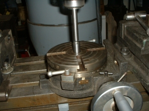
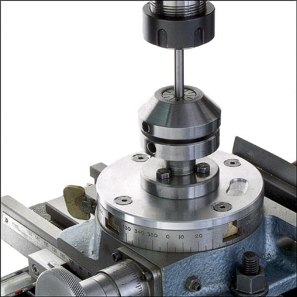
Is the rotary table axis above the X-Y slides as it appears? If you only need rotational motion you can flop it on your mill table anywhere convenient and clamp it down. Put a known circular object with enough weight not to move from indicator pressure on the table and get it centered by eye. Then with an indicator mounted anywhere convenient rotate the table and see how far out your object is. Tap it over toward center until you"re satisfied and now you have a circular table reference. Now mount the indicator in the spindle if it isn"t already, and move the mill"s X-Y to get your target object in line with the spindle.
If you trust the table"s outer rim sufficiently and your picture looks like rust could interfere, just mount the indicator in the spindle and with a sufficient extension sweep the rim.
If your rotary table is mounted close enough to the mill spindle centerline you could use the slides under it to re-position it sweeping the rim or your target.
Run the quill down and touch the sharpie to the rotary table table and by moving the mill table (cross feed) draw a line that will be parallel to the work.....
Now, use an indicator to final align the edge of the plate to be true to the machine ........Do this by rotating the table....Be sure to make all corrections by turning hand wheel in the direction that you will
If you have a moveable degree pointer for the table also set it to zero (most have some adjustment here)....If that is not available on your table make a simple sheet steel pointer plate that is just plain(no pointer.
Move to and cut features as needed...be sure to account for backlash in the table worm...(The starting point for the rotary cuts need to be positioned by moving in the direction you moved to set the plate to zero.)...

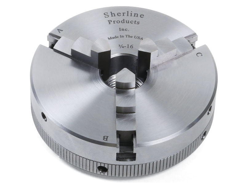
Description: Table diameter 80 mm (3") Table is graduated 360 Degrees. Worm Gear Ratio -1:36, which means that the 1 handle rotation shall turn the table by 10 Degrees. Center Height in vertical position without chuck: 2-5/8" (66 mm approx) Hand wheel is graduated in divisions of 10 min & can be set to zero. Can be mounted both in Horizontal & vertical position Supplied with a 65 mm 3 jaw self centering Chuck + Back Plate + T nuts for quick clamping
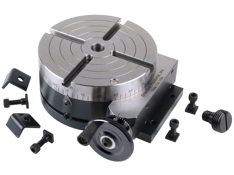
A rotary table used in conjunction with a mill allows a machinist to produce virtually any part they can design. Sherline’s rotary table is a precision piece of equipment that has been designed to work with their vertical milling machines. However, it can be used on any mill whenever the small 4-inch size would be an advantage. The only limits are size, not complexity.
The table is 2″ high and 4″ (100mm) in diameter. The main components have been machined from solid bar stock steel, and the complete unit weighs seven pounds. The table has been engraved with a laser, giving sharp and precise lines every 5°, numbered every 15°. These lines are calibrated with the 72-tooth worm gear that is driven by the handwheel. The handwheel is divided into 50 parts, making each line on the handwheel 1/10°. This allows a circle to be divided into 3600 increments without interpolation. Seventy-two revolutions of the handwheel rotate the table one revolution.
The rotary tables can hold more weight when they are not under a continuous load. Click on the Video tab above to see examples of different weights and uses for our rotary tables.
The table T-slots are identical to those used on the Sherline mill and lathe, making the vast line of Sherline tooling available for use with this product. Two hold-down clamps and T-nuts are provided with the table. Also included is an adapter that allows Sherline’s 3- and 4-jaw chucks to be screwed directly to the rotary table. An optional right-angle attachment is available (P/N 3701) to mount the table in the vertical position to increase its versatility further. With the table mounted vertically, an optional adjustable right-angle tailstock (P/N 3702) can be mounted to the mill table. It is used to support and stabilize the other end of long work held in a chuck or otherwise attached to the rotary table.
Kaka Industrial HV-8, 8”Horizontal Vertical Rotary Table Rotary table TSL Vertical & Horizontal MT3 Center Sleeve Rotary Table 4 slot Precision Milling Table 360 Degrees Precision Rotary Table
Kaka Industrial HV-4, 4”Horizontal Vertical Rotary Table Rotary table TSL Vertical & Horizontal MT3 Center Sleeve Rotary Table 3 slot Precision Milling Table 360 Degrees Precision Rotary Table

The 4-axis CNC milling machine cutting the sample parts with ball endmill tools. The 3-axis machining center attach the rotary table for cutting the sample parts.


 8613371530291