
centering rotary table made in china

Rotary table in market mainly includes 4 kinds of mechanism that is worm gear, roller cam, DD driver and harmonic structure. The following is the introduction:
1. worm gear: it’s one of the most popular structrue in NC rotary table because of its irreversibility and costs.The worm is generally made of bronze, but the wear resistance is poor. In order to improve the service life, some manufacturers use the alloy steel.
3.DD motor: it’s the most efficient rotary table with the highest precision. It has the highest precision because it has no mechanical structure, which is directly driven by motor , no reducer. It has high technical difficulty and high price. It is generally used for five axis machine tools.

Most small rotary tables have some sort of center hole, sometimes with a cylindrical bore but often with a Morse taper. If the part you"re wanting to center has its own center hole, you might be able to make a plug that fits the rotary table center hole and the part center hole.
The more common way of centering a workpiece on a rotary table requires that you measure the difference between workpiece radii that are 180 degrees apart, and then adjust the workpiece location on the rotary table to split the difference. The most common tool used to make the measurements is a dial gage or dial indicator that must be held stationary; most often the dial gage is anchored to the machine spindle while the rotary table base is clamped to the table.
After you center the work on the rotary table by eye, set a dial indicator up to probe the reference surface. Adjust the indicator holder or move the table so that the dial gage plunger is pressed about half way into its range of travel before zeroing the indicator. Now turn the rotary table top and workpiece (as an assembly) a half turn before reading the dial gage.
Now you want to move the workpiece relative to the rotary table surface until the dial gage reads one-half of the second value. Let"s say your two dial gage readings are A. 0.000 inch, and B. 0.138 inch . . . you want to move the workpiece until the dial gage reads 0.069 inch at BOTH positions A and B.
Since it"s about impossible to move the part on the table exactly the right amount in the right direction, it"s vital that you recheck and readjust A and B after you adjust along C and D . . . and then you"ll need to check and readjust C and D again, and so on and so on. While you"re learning, it"ll seem like you"re chasing your tail, but it is a skill you"ll learn.
To reiterate, the important part is that when adjusting the part on the table you need to rotate the part and table together when you make your measurements, NOT the machine table.
Then later, if you need to center the table under the spindle, you rotate the spindle to measure and move the machine table, which has the rotary table and part bolted to it, to make the adjustment.

The way that I was taught is that you have to make up a test bar. Take a piece of 12" by 1" roundbar, drill two centre holes in it"s ends, on your lathe and take a parallel cut between centres. Once you have corrected the error of your lathe and both ends of the test bar measure the same diameter, you can then use the test bar in your milling machine as well, to set the tailstock of the dividing head as well as the alignment of the bar to the table axis.
SanGo Automation Limited is a high quality manufacturer of Linear, Rotary, Servo, Cam driven automation components as well as Customized Intelligent Control System. SGA supplies the world with Linear Modules, Linear Motors, Smart Electric Cylinders, Smart Motorized Grippers, Cam Indexing Drives, Planetary Gearboxes, Harmonic Drives as well as Precision Hollow Rotary Table, etc.

After reading and thinking about all the advice and guidance I"ve received concerning alignment of my new rotary table, I assembled the following devices . . .
I put them together with the collet in the mill spindle and raised the knee being very careful to ensure that the end of the MT3 tool bit holder was inserted into the MT3 hole without touching any horizontal edge surfaces. The act of continuing to raise the knee until the MT3 tool bit holder was fully inserted pretty much centered the 118lb rotary table.
Above: The assembly fully inserted into the MT3 hole in the rotary table. At this point, the rotary table axis and the mill spindle axis are probably pretty much aligned good enough for my purposes. But, wait! There"s more!
I aligned like I tram the mill table: every 90* on the X and Y axis. The first time around, I discovered that after using my collet-MT3 assembly I was at the most 0.0008" out of alignment. I imagine this is plenty good for me, but I wanted to do better.
I was amazed by how tiny a force was necessary to move that big, 10" table one ten-thousandths of an inch! Plus, after all my concern, it proved very easy to do.
I don"t have one of these, but my experience with China made indicators is that the quality is far more that what you paid for. They seem to produce nice stuff of more than acceptable quality.
In order to indicate the RT table concentric to the spindle, one most attack the indicator to the spindle, center the RT as close as possible to the center of rotation of the spindle, then with the indicator do the final centering rotating the spindle by hand.
Now, for checking TR run-out precision, then all you need to do is pick a point inside the hole and rotate the table to see how much it variates from zero in 360*.
Now, the outside surface of the Rot table is not considered a precision surface. Checking to see how much run-out it has should be only for reference, but the MT and the pilot holes are relative to bearing rotation and the mounting surfaces (horizontal or vertical).
My mill may not have enough spindle to table clearance to justify buying one. The indicator method though crude in comparison to the coax, can do just as good or better job, just slower and more painful.
The backing plate will have a loose-fit (.0005" to .0010") pilot nipple and four c"sunk holes to screw the backing plate to the rot. table after with four T nuts. (plus the chuck centering step)
I want to align the mill spindle axis with the rotary table axis and then move the rotary table, say, 1.50" + the cutter radius along either the X or Y axis. Then, I will plunge an end mill through a quarter-inch thick piece of aluminum and rotate the table until I have created a 3" diameter circle which I will then create a bolt hole circle within.
Eventually, I DO want to put a backing plate and a chuck--probably 4-jaw--on the rotary table. Phase II does sell the backing plate, chuck, and tailstock if I want one. (I do.)
Truth be told, an adapter plate can be easily machined with only a mill and the use of the rotab. The plate should be no less than 5/8 thick, and more is desirable. All depends on the height of the SHCS"s used to secure the plate to the rotab. Aluminum is satisfactory for such an application, making machining easy! I"d recommend 6061-T6 as an alloy choice. 7075-T6 might be even better, but it"s more expensive and you"d not realize any particular benefits. An alternate choice would be the use of aluminum tooling plate, which is very stable, and already parallel and flat. It comes from the mill already surfaced, with both faces papered to protect the finish. It is cast aluminum, not rolled, so it isn"t as nice to machine, but would serve perfectly well for the intended purpose.
Using the mill, locate the four mounting holes that will be used for the plate, which should be larger in diameter than the chuck body diameter, to allow for the mounting bolts (SHCS"s). The holes would be on a bolt circle greater than the body diameter of the intended chuck, allowing enough clearance for the heads of the screws, but within the OD of the rotab. Chuck size is limited in this case, and must be at least 1½" smaller in diameter than the rotab table diameter.
Once both faces are parallel and flat, place the adapter back on the mill, dial in the roughed hole, and bore it to finish size. To accommodate long pieces, it"s desirable that the locating plug be able to be removed when the plate is fastened to the rotab, so it might be to your advantage to design a plug that can"t fall through the table, and is easy to grasp for removal.
After mounting the plate, which now has been faced, the bore taken to size, and a locating pin procured, you can carefully machine the plate to locate on the counterbore of the back side of the chuck you intend to use. The perimeter of the plate can also be machined once installed on the rotab, using an end mill. The plate should either be slightly larger in diameter than the rotab, to avoid hitting the table edge, or the plate can be mounted on thin parallels to provide needed clearance to avoid contacting the table with the end mill. A 45° chamfer can be machined on the edge using a 90° c"sink. Locate the mounting holes that match the tapped holes in the chuck, and counterbore them on the far side, to accommodate SHCS"s.
The entire project can be accomplished without the use of a lathe----but it will require a little thought. The locating pin can be made on the mill, using a boring head to turn the needed diameters. If one diameter happens to be a common collet size, the part can then be gripped in a collet, with a lathe tool held in the vise. Using the head power feed, and either the table or saddle for feed, size is then easily controlled.
The rotary table is an accessory for the CNC floor type boring and milling machine. It can be working together with the floor type boring milling machine for milling angle, reverse boring, polyhedral machining, and other complex machining processes. It could do five sides machining if the main machine equipped the angle milling head.
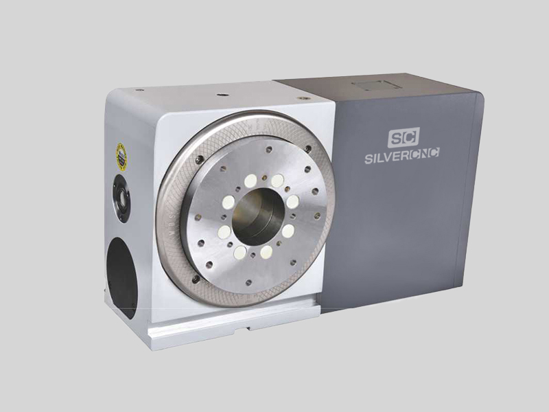
CNC rotary table is a common part of CNC milling machine, often used as a servo axis of CNC milling machine, namely C axis of vertical CNC milling machine and B axis of horizontal CNC milling machine. The CNC rotary table includes the foot of the turntable, a round turntable surface, four rolling bearing parts arranged on the upper surface of the foot of the turntable, and a center with a self-aligning bearing installed at the center of the upper surface of the foot of the turntable. Support, each rolling bearing component includes a rolling bearing and a support that supports the rolling bearing through the axle. The center of the lower surface of the turntable is provided with a vertical downward axle. The turntable is installed on the foot of the turntable. The inner ring of the self-aligning bearing is fixed, and the rotating surface of the rolling bearing is in rolling contact with the lower surface of the turntable surface.
The CNC rotary table has an inclinometer with two orthogonal test axes as the test tool. The inclinometer is set at the center of the turntable surface to be leveled, so that the two orthogonal test axes of the inclinometer are parallel to the turntable surface, by adjusting the milling machine turntable. The leveling mechanism under the base makes the tilt angle value output by the two test shafts of the inclinometer turntable in the leveling state.
CNC rotary table and swing head are the key components of multi-coordinate CNC machine tools. Traditional rotary tables and swing heads using high-precision worm gears and other transmissions are not only difficult to manufacture, costly, but also difficult to achieve the speed and accuracy required for high-speed machining. Therefore, it is necessary to develop a new electromagnetic drive system for the CNC milling machine turntable and swing head in a different way to realize the zero-drive drive of the rotational motion coordinates of the CNC machine tool.
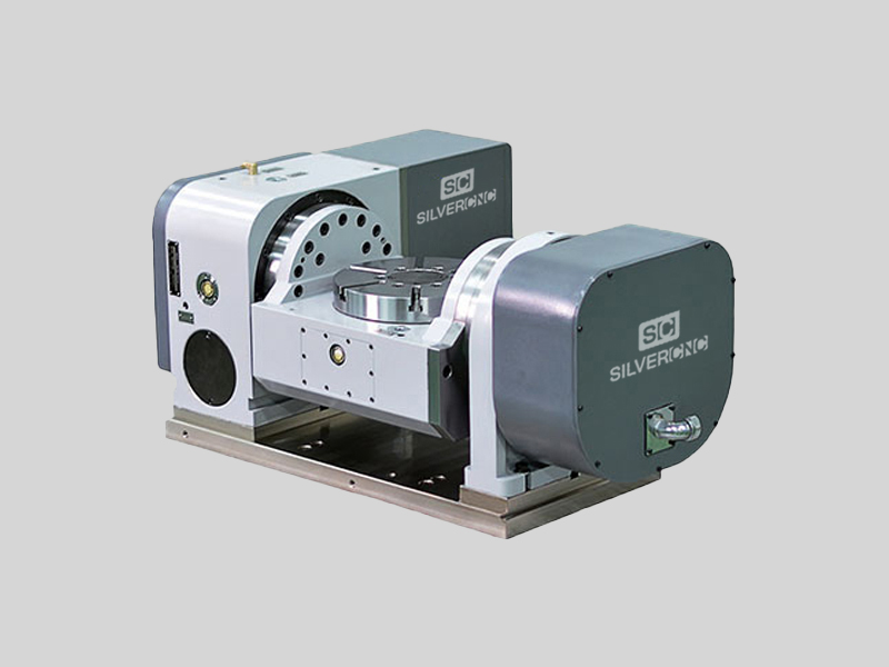
1. The CNC turntable uses modular design technology. The PAN turntable and TILT turntable are independent components, which are easy to disassemble and can be controlled by linkage or individually.


 8613371530291