
chuck rotary table free sample

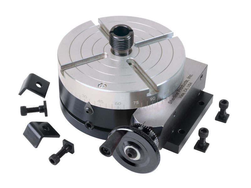
This is a modification of our 4″ Manual Rotary Table. This modification came about after requests from our laser engraving customers. They wanted a rotary table that had a larger through-hole to which they could mount our chucks.
This version of the Sherline rotary table has a Nickel-Teflon plating on the tabletop because it was designed to be used in an everyday production environment. This gives the table a rust-resistant surface that is hard and has added lubrication qualities.
The table is 2″ high and 4″ (100mm) in diameter. The main components have been machined from solid bar stock steel, and the complete unit weighs seven pounds. The table has been engraved with a laser, giving sharp and precise lines every 5°, numbered every 15°. These lines are calibrated with the 72-tooth worm gear that is driven by the handwheel or stepper motor. The handwheel is divided into 50 parts, making each line on the handwheel 1/10°. This allows a circle to be divided into 3600 increments without interpolation. Seventy-two revolutions of the handwheel rotate the table one revolution.
NOTE: You can have your manual rotary table upgraded to CNC-ready, but this is done as a factory-only replacement. You will need to ship your manual rotary table back to our factory for the conversion.
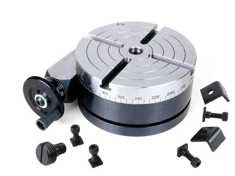
This is a modification of our 4″ CNC Rotary Table with Stepper Motor. This modification came about after requests from our laser engraving customers. They wanted a rotary table that had a larger through hole to which you could mount our chucks.
This version of the Sherline rotary table has a Nickel-Teflon plating on it because it was designed to be used in an every-day production environment. This gives the table a rust resistant surface that is hard and has added lubrication qualities.
The table is 2″ high and 4″ (100mm) in diameter. The main components have been machined from solid bar stock steel, and the complete unit weighs seven pounds. The table has been engraved with a laser, giving sharp and precise lines every 5°, numbered every 15°. These lines are calibrated with the 72-tooth worm gear that is driven by the handwheel or stepper motor. The handwheel is divided into 50 parts, making each line on the handwheel 1/10°. This allows a circle to be divided into 3600 increments without interpolation. Seventy-two revolutions of the handwheel rotate the table one revolution.

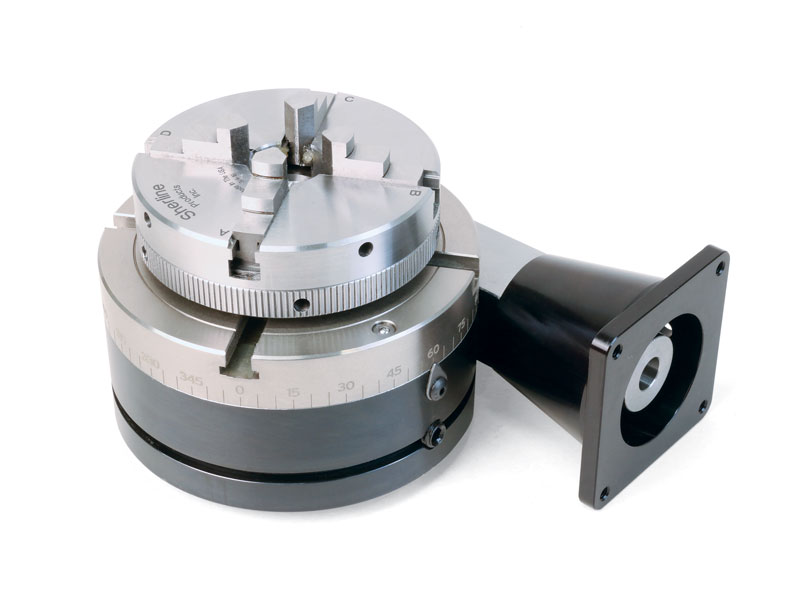
Control is very accurate and precise thanks to the direct mount self-locating 3-jaw chuck, 4° table movement per handle rotation, and 20 second vernier scale.
The T1190 manual was written by our U.S. based Technical Documentation Department and is packed with useful information. The complete and easy-to-read manual makes it easier to assemble and maintain your rotary table.
The Grizzly Customer Service and Technical Support Teams are U.S. based. Parts for the rotary table may be available online and shipped from the Grizzly parts warehouse in Springfield, MO.
Available for the Fusion Maker/Edge 12 - Edge/Pro 24 is the 3-Jaw Chuck Rotary Attachment. With this attachment, objects are clamped into the device"s 3-jaw chuck, allowing you to rotate cylindrical or oddly-shaped items in applications that demand more precise alignment.

Years ago, before I learned CNC, I owned a Phase II 8″ horizontal/vertical rotary table that I purchased from Kap Pullen’s Getmachinetools.com store. He has them at a good price, BTW, and he’s a darned nice fellow to deal with as well as being a frequent HSM contributor. Anyway, its a nice little table, but I hadn’t done a whole lot with it for quite a while after purchasing it. As is so often the case, one day, a project landed on my doorstep and I was glad to have it.
Before I could get started, however, I had to make some accessories for it. Basically, I needed some T-Nuts to fit the table, as well as a little fixture that makes it easy to hold a plate up off the table through a hole in the center so you can machine it. The latter, what I call a “plate machining fixture”, was inspired by something similar I saw the Widgitmaster of CNCZone fame using to make Dremel clamps for his mini-router:
I turned the round spigot using the 4-jaw on the lathe. I’m making the fixture out of MIC-6 aluminum plate, which is pre-ground very flat on the sides. This is a 5 inch by 3 inch piece. I’ve clamped it to the rotab using my T-nuts and the regular mill clamps and step blocks. It is sitting on parallels to make sure I don’t cut into the table. You can also see how I’ve clamped the rotary table to the mill table using a big cast iron V-block I have. You can never have to many blocks with precision faces hanging around!
Having a 4-jaw chuck on your rotary table is mighty handy! Because it’s a 4-jaw, you can dial in the workpiece by adjusting the jaws until it is perfectly concentric with the table’s axis of rotation. The best way is to make an adapter plate that attaches to the back of the chuck in the same way that your lathe does so you can exchange lathe tooling with the rotab. Here is an example:
For the example, the chuck is threaded onto the adaptor plate, and then the holes in the adapter plate’s flange are used to bolt down to T-nuts on the table.
In my case, I bought a 4-jaw from Shars brand new, and simply drilled some through-holes in the chuck to mount to the table directly without an adapter plate:
First, you want to make sure your part is properly centered on the table. To do that, I clamp the table down on the mill table (no special place is needed), put my Indicol indicator holder on the mill spindle, and find some round feature on the part to indicate on. For example, on the plate milling fixture above, indicate on the round boss, or on the center hole. Spin the table and bump the part in until spinning the table doesn’t move the indicator.
Second, locate the center of rotation directly under the mill spindle. You can simply use the X and Y table handwheels to do this. Use that Indicol to indicate off of a circular feature you want centered under the spindle. Turn the indicol around on the spindle and adjust the handwheels until the indicator stays put relative to the spindle position. A Blake Coaxial indicator will make this last even simpler.
When you’re rounding partially by cranking a part around on the rotary table, it’s really easy to go a little too far and screw things up. The answer is to drill the end points to make the exact stopping point on the rotab a lot less sensitive:
Centering with a Blake indicator is really fast, but what if you don’t have a Blake, or worse, what if your mill is too small to accomodate one? Here is a nice solution I found on a German site. This fellow has made an ER collect fixture for his rotary table, and has taken care that when installed on the table, the axis of the collet is aligned with the table’s axis. He can then place a dowel or other straight pin in the collet and line up until it will go into a similarly sized collet on the spindle. Nice trick! It’s similar to how Widgitmaster showed me to align a drill chuck on a QCTP to the lathe centerline with a dowel pin held in the lathe chuck.

A rotary table is a precision work positioning device used in metalworking. It enables the operator to drill or cut work at exact intervals around a fixed (usually horizontal or vertical) axis. Some rotary tables allow the use of index plates for indexing operations, and some can also be fitted with dividing plates that enable regular work positioning at divisions for which indexing plates are not available. A rotary fixture used in this fashion is more appropriately called a dividing head (indexing head).
The table shown is a manually operated type. Powered tables under the control of CNC machines are now available, and provide a fourth axis to CNC milling machines. Rotary tables are made with a solid base, which has provision for clamping onto another table or fixture. The actual table is a precision-machined disc to which the work piece is clamped (T slots are generally provided for this purpose). This disc can rotate freely, for indexing, or under the control of a worm (handwheel), with the worm wheel portion being made part of the actual table. High precision tables are driven by backlash compensating duplex worms.
The ratio between worm and table is generally 40:1, 72:1 or 90:1 but may be any ratio that can be easily divided exactly into 360°. This is for ease of use when indexing plates are available. A graduated dial and, often, a vernier scale enable the operator to position the table, and thus the work affixed to it with great accuracy.
Rotary tables are most commonly mounted "flat", with the table rotating around a vertical axis, in the same plane as the cutter of a vertical milling machine. An alternate setup is to mount the rotary table on its end (or mount it "flat" on a 90° angle plate), so that it rotates about a horizontal axis. In this configuration a tailstock can also be used, thus holding the workpiece "between centers."
With the table mounted on a secondary table, the workpiece is accurately centered on the rotary table"s axis, which in turn is centered on the cutting tool"s axis. All three axes are thus coaxial. From this point, the secondary table can be offset in either the X or Y direction to set the cutter the desired distance from the workpiece"s center. This allows concentric machining operations on the workpiece. Placing the workpiece eccentrically a set distance from the center permits more complex curves to be cut. As with other setups on a vertical mill, the milling operation can be either drilling a series of concentric, and possibly equidistant holes, or face or end milling either circular or semicircular shapes and contours.
with the addition of a compound table on top of the rotary table, the user can move the center of rotation to anywhere on the part being cut. This enables an arc to be cut at any place on the part.
Additionally, if converted to stepper motor operation, with a CNC milling machine and a tailstock, a rotary table allows many parts to be made on a mill that otherwise would require a lathe.
Rotary tables have many applications, including being used in the manufacture and inspection process of important elements in aerospace, automation and scientific industries. The use of rotary tables stretches as far as the film and animation industry, being used to obtain accuracy and precision in filming and photography.

production parts or sample from manufacturing process during hold by rotary chuck on table of high technology & precision automatic measuring machine for multi inspection dimension shape appearance
I"m a wanna-be machinist newbie. I have a small mill (no lathe). I obtained this small 6" rotary table (a Griz product). I would like to get a small 3-jaw chuck mounted to it, but have NO CLUE as to how to choose a chuck that will be compatible with this RoTab. Am I looking for a 6" chuck? Or 4"? I can"t go too "tall" or I waste all my Z axis. I don"t even know how the chuck would mount to the RoTab. The hole in the center is a MT#2, would a chuck use the MT? Or attached how?
Can someone guide me to some options regarding how to get a chuck on here, where to find the components needed? I am not looking for gold-plated accuracy. (It"s just an inexpensive $900 ChiCom mill with an inexpensive $250 ChiCom RoTab. Not proud of it, but I"m lucky to have it, and it works good enough.) In fact I"d love to buy a chuck used if possible and save some coin. Ideas?
More info on my intended useage of chuck-on-rotab, if you are interested: This RoTab will mount horizontal or vertical. With the RoTab in the vertical position, with its associated tailstock, I believe you can "fake" some lathe operations on a mill. I need to do some small lathe operations with it, which will entail bringing down an endmill to the work and then slowly turning the RoTab. So sort of reverse of a lathe, in this setup the bit is powered and the work is being turned slowly by hand. Yeah, I wish had a lathe but in this obanomy, you make do with what you got.
Alternately, I think I can do some vertical lathing without the RoTab. If the stock is small enough to go into the mill"s chuck (5/8 max) and stout enough to hang free, some lathing can be done by clamping a lathe bit in the vise and running it up and down the work using the Z axis. For small work only.
I suppose you could also chuck a larger round piece in the rotab/chuck (with the rotab/chuck in the horizontal position, and the work sticking up vertically), and use an endmill to make bushings, and other short, squat round work, etc. by spinning the work in the rotab/chuck against the endmill.


 8613371530291