
cutting gears with a rotary table brands

The handle can be removed easily by releasing the caphead bolt. The handle being located with a keyway. This then allows the dividing plates and crank to be fitted in place of the free-rotating handle.
The crank handle is held in place with a grub screw – ensure this is tight and that the handle and pin are at 90° to the crank plate before trying to fit the crank to the table.
12 divisions is achieved with 7.5 turns – so 7 complete turns of the handle and then with a 20 division plate the dividers are set at 10 + 1 holes apart.
his takes a bit of concentration to use as you count off the rotations and then add the part rotation needed for the division – just be consistent and all will be fine.
A very small 12 tooth gear made with a cutter designed for a larger number of teeth and hence the undercut on the teeth – the wall is rather thin at the centre, but this was a trial to see how the rotary table works when being used as a divider – aim is to make more gears for my Wood and Metal Clock.
A pair of gears cut together out of mild steel – 60 teeth and 43mm diameter. One of these is for the camshaft side of a four-stroke engine in construction.
I created a quick google spreadsheet (below) that gives me divisions up to 200 and for completeness the first row gives 360 divisions. I have added a link to a downloadable pdf version if that helps. Note: number of hole intervals means you need to count the hole that the pin is in as 0 and then count out the number of intervals/steps from there (next step being 1).
A freely available spreadsheet that has the full dividing plate and rotary table calculations. You can set it up for your specific table and print off the sheets. You just need to know the worm drive ratio.

I think as rotary table with index plates and a tailstock might be a bit more versatile than a dividing head. You can use its flat table to clamp projects down on,like a face plate. You can add a chuck. You can still cut gear teeth with the dividing attachment. A universal index head can tilt,but a rotary table can too,if you mount it on a tilting table. Less rigid on a tilting table,but I like using the flat table better than other short comings it might have.

CNC Indexing & Feeding Technologies is proud to represent the TJR line of rotary tables, indexers and accessories. TJR originated as a rotary table sales and service agent and established itself as an OEM in 2009.
TJR tables feature an anti-wearing worm gear, durable, high-tensile brass shafts, and braking systems with a large clamping range. All new TJR tables come standard with a 3-year parts warranty.
Standard Rotary Tables. The AR Series is TJR’s standard 4th axis pneumatic brake rotary table. It is offered in both a Right hand motor mounting and Left hand motor mounting option. The HR Series is TJR’s standard hydraulic brake 4th axis rotary table.
CNC Indexing & Feeding Technologies offers a wide range of TJR rotary tables. However, many are unclear about what rotary tables can do for their business, as well as how they work in CNC machining. First, let’s consider the basics about a rotary table and how it works in the machining and manufacturing processes.
Milling and other industrial processes require cutting and shaping, usually with a high degree of precision. This creates the need for computer-guided systems that can create workpieces, prototypes or tools for companies on demand. The process is expedited, reducing or removing the need for large assembly line staff or other hand crafters.
In many cases, the work pieces created through CNC machining would be impossible without computer assistance. The code used to communicate between the CNC machine and computer software is specialized. Older machines, or manual machines, used hard wired controllers. However, new CNC machines rely on modern devices like CDs, USB drives, networks and so on.
A lathe or milling machine requires its own set of parts to work sufficiently. For example, an indexing head is needed to allow circular shaping. The indexing element allows the piece to be rotated at an angle or even divided into sections.
A rotary table can tilt and rotate. The table makes use of the indexing head in order to cut according to a specific technique. This makes it possible for the machine to create a workpiece with complete flexibility in rotation and angling.
A rotary table can help to create arcs and circles, an important process in part or tool fabrication. Tools can be specially made, such as car parts, machine parts, and many other objects.
The CNC process lets companies make straight cuts even with multiple angles and to cut small objects into even smaller parts. CNC rotary tables can also help in the processes of cutting gears, drilling or cutting holes.
The table can also be used along with a dividing head and index plate, to further concentrate the shaping. Tables are also used to hold certain parts for superior milling techniques.
Adding rotary tables will improve your capacity to produce the parts you want and increase profits. This brings us to the primary advantage of CNC rotary tables: less time and greater accuracy in cutting.
Companies are often outsourced to create work pieces for larger brands. However, some companies simply create their own prototypes, tools or work pieces with their own facility for machining. There are also contract shops, mechanic shops, electronics companies, inventors, engineering, and retail companies.
Most companies save costs by scaling their needs with small productions. In many cases, they may only have one facility or work with one type of part. The key is not to create “anything” but to specialize in objects created so the process can be streamlined.
The benefits of using cnc rotary tables include consistency, faster production and increased capacity. Products and work pieces assembled through CNC systems are more reliable than products created manually or through other methods. The process is identical each and every time, so consistency can be guaranteed. This is critical for a company trying to ensure safety protocol.
Flexibility is another advantage, as the systems are programmable. These systems are designed to minimize downtime in between their running processes, offering greater flexibility.
The capacity of complexity of product is another benefit. Complex motions are made simpler by CNC rotary tables, making them more affordable to produce.
Naturally, such an intricate process cannot be unsupervised, since efficiency depends on optimal performance. A supervisor must oversee a rotary table operating with CNC controls to ensure the machine and software are configured correctly.
This involves setting the system up, installing the software, and watching over the production. If something goes wrong, the software must be fixed and the machine repaired. Machines are not constantly running, but must be evaluated and cleaned regularly, ensuring that they will be mostly self-sufficient.
We offer a wide variety of rotary tables to meet all of your needs. This includes standard rotary tables with full rotating axis capabilities, and vertical and horizontal mounting positions.
We also offer large rotary tables with hydraulic brake systems, which allow higher clamping torques. You can also find assistance with smaller rear mount rotary tables or tilt rotary tables.
Horizontal rotary tables are specially made for horizontal mounting and carrying a much heavier weight. Horizontal index tables are available, whether in manual or CNC index tables style. Finally, there are face gear rotary tables and rotary table accessories, ideal for projects that need higher degrees of accuracy.
Remember that quality production is synonymous with efficiency and accuracy. Product producers must have the right equipment operating at full capacity in order to guarantee consistency.
CNC Indexing & Feeding Technologies can help you find the machine tool accessories you need to meet your production demands. This includes simple rotating feature, larger work pieces, vertical and horizontal applications, or even 4 or 5 axis work. With TJR rotary tables, you can improve your cycle and process time, reduce your down time and increase your profits.
You can always reach us if you have additional questions regarding how to get started by calling us at 513.770.4200. It’s time to expand your business and your capability!

The TR160 5 Axis Rotary Tables, manufactured by Haas, consist of dual axis Trunnion rotary table that is capable of tilting up to 160 mm. It also has a scale assessment ...
The TR210 is HAAS"S rotary table developed and configured to be integrated with HAAS"S mills 4th and 5th axis drivers to provide complete and optimum operation. It has a diameter of 210 mm made from trunnion ...
... space with high load capacity. The individual rotary tables are equipped with Harmonic Drive units, which ensure high moment load capacities and high concentricity and axial runout accuracies.
The work table is graduated 360 degrees around its circumference and is driven by a precision Worm and Gear providing a 90:1 reduction ratio. One turn of the Handle moves the Table through 4 degrees. ...
... Tilt-Yaw (A/B) two-axis rotary assembly provides high-speed machining capabilities for complex 3D part geometries. The precision-aligned system allows accurate positioning on a hemispherical surface. ...
... ) MDR two-axis rotary assembly provides high-speed machining capabilities for complex 3D part geometries. The precision-aligned system allows accurate positioning on a hemispherical surface. Uses cost-effective ...
... ) MDR two-axis rotary assembly provides high-speed machining capabilities for complex 3D part geometries. The precision-aligned system allows accurate positioning on a hemispherical surface. Uses cost-effective ...
Our FÖRSTER swivel welding tables offer maximum working comfort for all-round welding of complex assemblies. Ideal for all tasks due to a variable arrangement of our patented T-slot system.
The hydrostatic rotary tables from ZOLLERN impress with their durability and a high concentricity and axial runout accuracy. Thanks to the ZOLLERN bearing clearance compensator, the optimal pocket pressure ...
... the table is the rotation, the user may require the rotary table for drilling operations and milling. Using the servo drives in conjunction with the machine CNC control ...
With DirectIndustry you can: Find the product, subcontractor or service provider you need | Find a nearby distributor or reseller| Contact the manufacturer to get a quote or a price | Examine product characteristics and technical specifications for major brands | View PDF catalogues and other online documentation

The TR160 5 Axis Rotary Tables, manufactured by Haas, consist of dual axis Trunnion rotary table that is capable of tilting up to 160 mm. It also has a scale assessment ...
The TR210 is HAAS"S rotary table developed and configured to be integrated with HAAS"S mills 4th and 5th axis drivers to provide complete and optimum operation. It has a diameter of 210 mm made from trunnion ...
... space with high load capacity. The individual rotary tables are equipped with Harmonic Drive units, which ensure high moment load capacities and high concentricity and axial runout accuracies.
... accumulation turntables are made from the highest quality stainless steel and can be supplied in numerous sizes. They are utilized for the collection of filled bags, bottles and packages and can be added to an existing ...
The new CNC Rotary Table from GANRO has got higher speed and higher clamping torque. Thus making it suitable for machining complex components like turbine blades, when used ...
This is the smallest CNC Rotary Table manufactured by Nikken Kosaksuho in Osaka, Japan. With pneumatic clamping this rotary table is used by many on ...
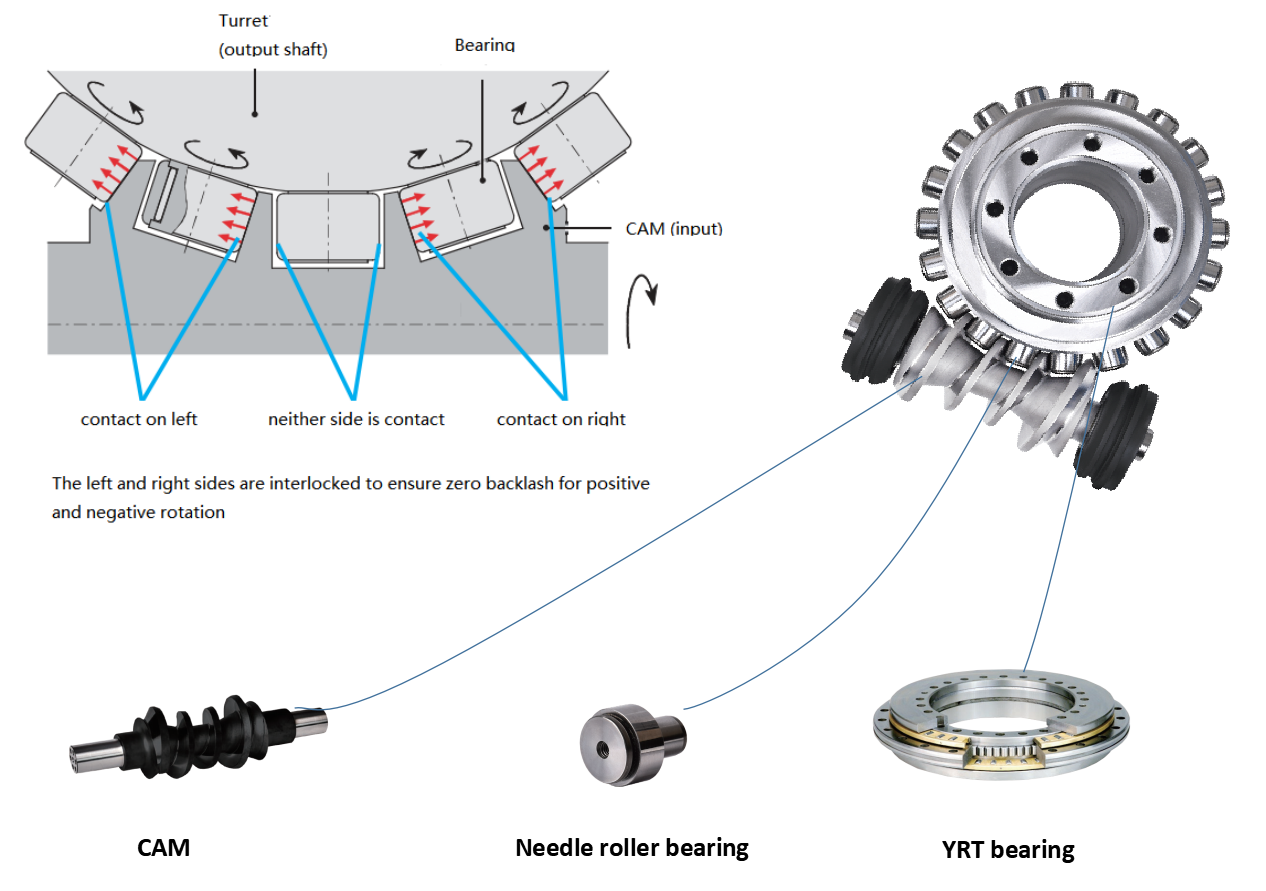
The main part of the RollerDrive mechanism consists of an input shaft and an output turret in which roller followers are embedded. An integral cross-roller bearing supports the output turret with ...
... high-performance and flexible series from Peiseler. An extremely modern design with a good price characterises these NC rotary tables. The basis for this successful design is the complete ...
... Drive Rotary Table is a kind of rotary table used to the continuous operation which is several times more agile and accurate than conventional face gear or rack and pinion ...
CNC rotary tables of the ETS series are our solution for your 4th axis. The ETS models are equipped with a spindle holder according to ISO 702-1. Interchangeable discs for all common ...
Directly driven Motor Power Company"s rotary tables, provide versatile applications due to their backlash free structure. If necessary a compact servo system with high torque and high accuracy, SKA Rotary ...
... combination case of Large Aperture Rotary Table with planetary reducer with model number GSN200M-50K-SV which has table size 200mm gear ratio 1:50 for servo motor. GIGAGER provides combination ...
With DirectIndustry you can: Find the product, subcontractor or service provider you need | Find a nearby distributor or reseller| Contact the manufacturer to get a quote or a price | Examine product characteristics and technical specifications for major brands | View PDF catalogues and other online documentation

Many rotary table manufacturers outsource gear fabrication to lower costs. While that strategy may offer short term cost savings, Index Design’s American made rotary tables are built with gears cut in house. This is the only way to closely monitor and control tolerances, consistency and performance.
Our rotary tables incorporate large diameter high tensile bronze worm gears mated against hardened steel drive shafts. The combination of metal gives superior wear properties for long lasting operation. As the rotary table is run, the properties of a tin bronze gear develops a low friction deposit on the mating steel drive shaft. These deposits fill in microscopic pores of the mating surface. Over time, as these deposits are embedded on the surface, wear decreases followed by a reduction in frictional forces within the gear assembly.
Final inspection and verification of specification performance is done with precision calibration equipment capable of measure tolerances of +/- 1 arc second in any position. Any deviations from specified angular positions are corrected so our customers can be assured that they are receiving the performance we guarantee.
In addition, the data gathered from our automated calibration procedure allow our engineers to assess, monitor and improve the static and dynamic performance of prototype rotary tables during the design phase.
Our engineers have a long and rich history in the machine tool business, they combine decades of both CNC machine tool and rotary table manufacturing experience with the latest design tools to produce rotary tables with superior performance and dependability.
Our CAD/CAM software is used to analyze displacement and stress for each component, sub-assembly and total assembly. However, the best software and technology is worth next to nothing if no one understands the craftsmanship. This is particularly true when manufacturing precision rotary tables which involves many steps. Despite all the modernization and automation available, a large part of the manufacturing process is still completed by hand. At Index Designs, we understand and appreciate craftsmanship, It is designed and built into our products.

Penn Tool Co. has a variety of precision rotary tables for sale. Simplify your production work with a rotary table that can be used for many different machining applications. In production, it is essential that jobs are done quickly, efficiently, and precisely. In the industry of intricate metalworking, precision matters and can make all the difference. All of the parts should look identical in the end, and our tools can help you do just that. To ensure quality and durability, we only carry top-rated, premium brands you can trust including Vertex, Harig and Phase II. With an easy-to-operate precision rotary tablefrom Penn Tool Co., get the accuracy you need and a timely, beautiful end result. Browse our collection, and order today!

SteveEx30 cutting the teeth in plastic goes pretty quick,probably a couple hrs.I got 3 gears out of that blank after the teeth were cut.That Nyloil MDX was a pain in the ass to part off.You nave to use plenty of coolant.The stringers will not chip and make a much stronger stringer than Delrin.If you stop before you part off completely it wraps tightly in the groove and takes a while to pull out before you proceed.I have found,with plastic and brass that when cutting multiple gears that it is quicker to cut the teeth first first then part off the blanks.It is easier to finish the blanks and then cut the teeth but you have to make a more complicated mandril and have to change blanks one at a time.I was able to stay on cutting the teeth to completion,but had to wait a day after I set up before I could start,then several days before I could finish because of breakdowns,other priorities.So it is hard to figure exact time but maybe 3 hrs per gear.Since these types of jobs are added value of my own initiative the time factor is not as critical as it would be in a job shop with a customer waiting.One good thing about this place is that I am allowed to tackle any job that I think I can do.I am 70 years old and when I think about retiring,my hobby would be dicking around in my shop doing basically the same thing as I do at work,without the insurance,pay and benefits!

A CNC rotary table is the precision positioning accessory that can provide a reliable 4th axis or even 5th axis for modern machining centers. Utilizing a computer-controlled rotary table can turn the original 3-axis machine tools into 5-axis CNC machines, expanding the accuracy as well as decreasing the costs while performing complex machining operations at one time.
A CNC rotary table is the precision positioning accessory that can provide reliable 4 or even 5 axis cutting operation capabilities for modern machining centers. Utilizing it can turn the original 3-axis machine tools into 5-axis CNC machines, expanding the accuracy as well as decreasing the costs while performing complex machining operations.
Rotary tables typically have rigid frames and coatings, and also excellent torque capacity, which makes the small device flexible and effective for a wide variety of turning, milling, drilling, and more metalworking operations. The easy setup and seamless interface allow the operators to easily add the rotary table to fit their 4-axis or 5-axis applications. .
The working principle is similar to the basic rotary tables, which is to support the workpiece by accurately rotating the workpieces on the axis in order to locate the parts for high precision tooling. Under rapid rotation, which is driven by CNC instructions, the cutting tools of larger machine tools or machining centers can remove the material and add the feature to the products at exact intervals. On rotary tables, there are vertical and horizontal axes for various tools to perform these high-performance metalworks. To enhance the accuracy and flexibility, there are models that employ additional dividing plates and come with additonal material handling mechanisms and features.
Since 4-axis and 5-axis machining is increasingly popular today, adding the CNC rotary table as the 4th axis is an ideal solution to easily open up more complex machining options at a lower cost. Due to the arrangement, they are widely also called the 4th or 5th axis or tilt rotary. The 4th axis, which is the rotational operational direction, is added to the original three linear axes which are known as X-axis, Y-axis, Z-axis. In some cases, there are two rotational axes add to the original 3-axis machining center, achieving utmost accuracy as well as effective multiple face cutting to reach the difficult area on the surface. Rotary tables are usually mounted parallel to the ground or the bed, with the platter rotating around the vertical axis, for example with the most common vertical milling machine combination. Sometimes the machining application requires an alternative setup with the table mountet on its end so that it rotates around the horizontlal axis. Often, a tailstock is used in this configuration. Virtually all models today come with a clamping kit to mount it onto the bed of your machine tool.
The function of the high precision rotary table is also to rotate the workpiece so the cutting tool can create the contour we desired out of the workpiece. However, a rotary table with higher precision has the ability to achieve great accuracy just as its name implies. There is also a major misconception between the resolution and the accuracy.
A common example is that if a digital readout displays to four decimal places, then the high precision rotary table must also be capable of achieving the accuracy to that same value. Even though for higher accuracy to be achieved, the resolution has to also be high, but there is no guarantee that the accuracy is going to be high. The accuracy is the concept which is the difference between the actual position and the position measured by a reference measurement device. The feedback mechanism such as the rotary encoder, and the drive mechanism can influence the accuracy of the advanced rotary table.
A CNC rotary table can provide great rigidity for stable machining operations. It consists of the worktable where the metal parts are held, the rigid bearing that withstands the forces and loads during the rotation, the solid base which is used for attaching the rotary table to the machining center or other equipment, the motor, and the CNC system.
The worktable is the tooling surface where the workpieces are machined after accurate positioning. The worm gearing is the core mechanism of the table, which mesh with the steel worm which is submerged in the lubricants. Both the rigid bearings and the worm gears have large diameters. Excellent concentricity is the key to smooth operation, durability, and most importantly, accuracy. Driven by a computer and electric motor, the worktable can position the materials at exact intervals. For more flexible or critical operations, dividing plates can be added to this component.
A CNC system regulates the simultaneous 4-axis motion of the rotary table. The instructions are programmed and transmitted via CAD software, reducing the time for adjustment and monitoring by human workers.
The type and size of the electric motors utilized in can define the router accuracy as well as the efficiency of the device. Servo motor and stepper motor are two typical types that can be divided into more subtypes. The servo motor uses a closed looping variable circuit, the circuit will constantly run to keep the function. The brushes must be replaced every 2000 hours of operation in the servo motor. Compared to stepper motors, servo motors are more efficient in power consumption. On the other hand, the stepper motor has a simpler setup which are the wires that are attached to the driver. The bearing of the stepper motor is the only wearing component. However, the stepper motor consumes a great amount of energy.
There are currently several different types and models available in the industries. Each of them possess its own traits and abilities. Let us take a look at the most common ones other than standard three axis tables
The 4 axis CNC rotary table will process the workpieces by holding them in the same position while the cutting tool performs along the XYZ plane to trim away the unwanted material. In general, a 4 axis model is very versatile equipment that can be used for several different industrial processes such as engraving curved surfaces, continuous cutting, and intermittent cutting. Besides, people can also add other devices such as cam machining, blade machining, and helical grooves to the 4 axes rotary table. Such a feature is simply impossible to achieve with the machining center which has only 3 axes.
Besides the 4 axis ones, there are also 5 axis models. They have the ability to allow the workpiece to be processed automatically from five sides at one time. people usually utilized the 5 axes rotary table in the industries such as the automobile, the aerospace, and the boating industries. The reason that the 5 axes rotary table is commonly used in heavy industries is that the 5 axis machining is an important technique to be used when the components need better intricacy and quick precision. All of these have more than three axes are called the multi-axis rotary table.
The installation method of the precision rotary table can be horizontal, vertical or inverted. When installed horizontally, the workbench surface is in a flat, vertical and horizontal position. When installed vertically, a rotary table is installed so that the surface of it can run up and down. In the reverse layout, itcan be rotated upside down in a horizontal position. The location of the drive of the rotary table can depend on the mount. The drive can be placed on the back, below, on the top or on the side.
When mounted horizontally, the spinning table top drive is positioned above the table floor. When the rotary table is horizontally placed, the side-mounted drive is located on the edge of the table board. The driving mechanism of the rotary table may be manual, electrical, pneumatic, hydraulic or non-driven. For manual revolving workbenches, release the workbenches and manually spin the workbenches with the crank.
Workpieces are gathered and machined through PC and fully programmed instructions. The 5-axis simultaneous operations will be measurably more reliable than products machined via different technologies. Also, the setup is simple and provides an indistinguishable process in every production cycle, the consistency of the quality of the metal products can be ensured under critical control and precision cutting.
Since the metalwork is driven by software, the preferred frameworks can be programmed and adapted by the rotary table. Saving both the cost and the room makes themis the ideal solution for potential users who don’t want to install larger equipment and new machines which may take up a great room for a wide variety of machining applications.
Another benefit is the utmost movements can be completed precisiely and faster. There are more favorable positions, operation angles as well as accessible machining that can be achieved through the technology. The complex operations are suitable for blade, helical grooves production, and other applications required to add complex features or require critical inspection in machining processes like the manufacturing of aerospace, automotive parts, and scientific equipment.
Addding a rotational table saves time because the extra finishing jobs or other sub-operations can also be performed at one time in the machining center.
A rotary table can be used in many applications including manufacturing, inspection, and assembly. Indicators are used, for example, for assembly, manufacturing, and bottling equipment. They typically use a single item in workspaces or move relatively small layouts of items around stations for sequential work or assembly.
In automated assembly machines, the rotary tables implementation is widespread, and choosing the right mechanism is important for both improving efficiency and reducing the cost of this vital component. This guide discusses two common devices for rotating indexing and offers guidance on the right range. There are several ways to get mass mobilization when it comes to the development of rotary indexing tables. Regardless of whether the load or load in centuries of thousands of kgm2 is incredibly light. When choosing a robust rotary index solution that will match or meet your standards, there are several factors to take into account when spinning, elevating, or pushing.
When determining the influencing factors on the postitioning accuracy, the first thing to look at is the mechanical properties of the table itself. A rotary table contains six degrees of freedom. Each of these movements increases the total risk of positioning errors. Usually, a rotary table is driven by a worm gear, which is connected to the motor through a rotary encoder on the back. The position of the table can be determined by the number of pulses transmitted from the encoder to the control device.
The four main sources of error due to the semi-closed position loop are geometric errors, thermal deformation, elasticity, and wear. The sum of these errors is called angular positioning error. To greatly reduce the angular positioning error, the ideal position for installing the angle encoder is on the rotating shaft under test. The angle encoder is installed under the rotary table, and the rotary encoder is installed under the rear motor, the position loop is now considered a closed-loop system.
Precision is a relative term. About a quarter of an inch is great and will meet the accuracy of its application. Others, for example, require micron-level accuracy in measuring and indexing devices. Then, some applications fall within these extreme ranges.
The misunderstanding is that you may have used an inaccurate indexing device and made it accurate by introducing a pin or wedge locking device. These devices increase the complexity and cycle time of use, and when they are used together with a high-precision positioning device, they may cause damage and reduce accuracy.
In the actual test, by selecting specific components, motion index drive, servo rotary indexer, the measurement accuracy is as high as 5-6 microns. These are not the results approved by Motion Index Drives, but the results of customer certification. When starting and stopping large amounts of data, it is important to know how fast it takes to stop the application with large amounts of data.
In a less rigid environment or the presence of higher recoil, a faster start and stop will bring many control problems. When moving masses (whether rotating mass or linear mass), starting and stopping in a system with a backlash of several arc minutes will cause a lot of back and forth movement in the gear system. The result is a force that is difficult or even impossible to calculate. In addition, when the gear head is used in rotating applications, the farther the mass is from the center of rotation, the greater the backlash. In applications with very slow deceleration times, recoil may not be a problem.
Backlash in the positioning process is a big issue – when it comes to the beginning and stopping volumes, it"s crucial to know how quickly you need to avoid the mass of your rotary indexing table applications. In a less rigid system or where there is an increased backlash, quicker start-ups and stops can cause a lot of control issues. When shifting a mass, whether rotary or linear, starting and stopping in a system with several minutes of backlash arc will create a lot of back-and-forth motion within the gearing system. The effect is a power that can be difficult and probably hard to quantify. In comparison, as the gear head is used for rotational applications, the more the mass is from the axis of rotation, the further the backlash is magnified.
The backlash may not be a concern in systems where deceleration times are incredibly long. In the case of cam indexers, there is " Zero Backlash." The cam indexer and rotary table dynamics give an incredibly rigid, highly regulated framework. A modern cam indexer system is capable of withstanding short cycle times with stop times in milliseconds.
So you want to get the smart manufacturing going but are not sure of what to look for in rotary tables. The information provided in this section may be able to help. The primary factor is to determine the mass snapshot of inactivity. This is often overlooked when measuring a rotary table for the machine.
Another significant factor is the size of the workpiece being rotated, including how big it is and how substantial it is. You want your rotary tables to be large enough to handle enormous pieces. This is where tilling rotary tables may become handy so that the pieces can be handled without causing interior harm. They allow the quickening and decelerating of machining at appropriate rates.
The last factor is accuracy, the applications for which, for instance, pivoting a gigantic part to allow welding highlights on it where the individual stop positions can be genuinely free. On an additional note, when choosing direct drive rotary tables, factors that you should consider when selecting a rotary table for your CNC machinery include accuracy, backlash, mass moment of inertia, acceleration and deceleration, speed, and environment.
Indexing system use is commonly possible in automatic assembly machines and the right process is important for both performance maximization and cost reduction.
Cam indexers are an omnipresent tool used for several decades for rotary indexing tables. They are suitable for applications that often index the same angle and need a high degree of accuracy at a relatively low cost. To place the load, a cam indexer uses a mechanical cam. A math curve is pushed onto the cam and provides incredibly smooth and repeatable movement.
Another popular alternative is a fully programmable rotary index table. A rotary table is advantageous in two different situations. Firstly, a versatile movement pattern is important. An example is if two components are running on one computer, each of which requires different index patterns. For incredibly fast placement accompanied by a long period, another condition that matches the servo pointer is. The need to accelerate the camshaft while the cam indexing mechanism was operating before starting the output movement reduced the on-demand cam indexer. Acceleration of the camshaft is possible, but there is a delay before the movement begins. There are realistic restrictions.
With an indexing table, the output rotates as soon as the servo starts moving. This is not difficult for a continuous cam indexer or a zero-backlash servo indexer, but it can also be difficult for an on-demand cam indexer. For applications with high-speed servo indexing, smooth movements are crucial. A zero-backlash preloaded reducer can achieve this. The ideal alternative for correct positioning with high dynamic response would be the zero-backlash reel drive system.
Application parameters, like a moment of inertia, indexing angle, indexing period, and residence time, are required for each indexer style. The rotary indexing table for the application should also be sized correctly by a reputable manufacturer.
The basic components of high-precision machinery, such as gears, cutting tools and bearings, have very high precision requirements and are difficult to machining. In addition, precision medical parts, clocks and other industries also have very strict requirements for metal machining accuracy.
To process these precision parts, we need to choose a rotary table with high precision, high efficiency and stable operation. Through structural innovation and continuous optimization and improvement in materials and processes, Silvercnc Tech rotary table fully meets the requirements of machining high-precision parts

Manufacturer of standard and custom 360 degree linear rotary tables for scanning, assembly, testing and production applications. Features vary depending upon model, including worm and gear drive design with central rotating ball bearings, manual and motorized operation, hollow spindles, four mounting holes, accessible adjustment clamps and graduated knobs. Accessories such as rotating table adapter plates, brackets, platform shelves, thumbscrew locks, alternative knobs, limit switches provided. Manually operated rotary motion turntables also available. Suitable for mounting and rotation of test specimens, cameras, transducers, sensors, mirrors and other components. Stock items and repair services are offered. One year warranty. Made in the USA.

Prop 65 Warning(s)Many metalworking products contain chemicals or metals included in the latest Prop 65 warning. Exposure may cause cancer and reproductive harm. KBC is currently gathering required California Prop 65 warnings for our customers. For more information go to www.P65Warnings.ca.gov

Fig. 4—On this tilting rotary table, one servo controls rotation, another controls tilt. Both servocontrols are slaves to the CNC with RS-232 communication, providing five-axis capability from a standard three-axis CNC.
Fig. 1—Modern rotary tables such as this one from SMW Systems have large, widely spaced spindle bearings, large diameter wormwheels and built-in spindle brakes.
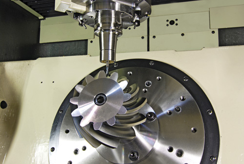
If you want to make parts similar to the complex valve body (upper left), an indexer using M-code, RS-232, or “full fourth axis” control is appropriate. Only positioning and rotary cutting moves are required. The center workpiece is a cam that requires simultaneous rotary and linear moves. You’ll need full four-axis control for such workpieces. If you want to do parts similar to the impeller on the right, the contour cutting will require simultaneous five-axis machining.
Many plant managers and shop owners dream of having the latest horizontal machining center (HMC) with all its features, benefits and sophisticated capability. While typical HMC features such as an automatic pallet changer and a 100+ cutting tool magazine are valuable, perhaps the most valuable characteristic is the HMC’s ability to machine on more than one side of the workpiece due to a built-in indexer or full fourth axis.
On complex workpieces that require machining on surfaces not 90 or 180 degrees from each other, indexing or fourth-axis rotation is almost essential to produce the piece. Even when rectangular workpieces with all surfaces 90 or 180 degrees from each other are put on a tombstone, the HMC’s built-in fourth axis of rotation creates a productivity advantage. This is true even if machining on more than one side of the part is not essential.
Any time you can increase the “run cycle,” do more cutting in one operation and avoid handling the workpiece, productivity goes up. Workpiece accuracy also improves. Unclamping and refixturing a workpiece to present a different surface to the cutting tool is always going to introduce some error.
The high cost of horizontal machining centers compared to the incredible values available today in vertical machining centers puts horizontals out of reach for many shops. Fortunately, today there are several suppliers of quality accessories that allow the VMC shop to equip its verticals with indexers, fourth axes and tombstones. These add-ons really work and give many of the benefits of an HMC at a fraction of the price.
Earlier rotary tables and indexers didn’t have the accuracy, rigidity or control flexibility of today’s models. Many shops that tried using indexers in the past had been disappointed in the performance of the older models and abandoned their use in favor of multiple operations, multiple holding fixtures and multiple handlings of the workpiece. They decided that the manual, multiple-operation process was better than trying to use ineffective early model indexers and rotary tables. Today, the situation is different. Manufacturers now offer units that are very accurate, very rigid and have a variety of control and interface options.
The best indexer and control system for you depend on the work you need to do. As with most things, different designs compromise certain capabilities to gain others. Unless you understand these trade-offs, you are at risk of selecting something other than the best system for your requirements. Let’s see what’s available, review the differing capabilities and discuss the advantages and disadvantages of each design. Once you understand the options, you can evaluate them against your requirements and then consider prices and suppliers.
Of course, such a system does not exist. Add the “lowest price from the supplier that gives the best service and support” component and it probably never will exist.
Terminology in the area of indexers is not standard. Terms such as fourth axis, indexer, rotary table and so on are used interchangeably by different machine tool and accessory companies. So, when selecting and buying, you must ask a few questions before assuming you know what you’re going to get. Also, beware of terms such as “precision,” “high precision,” “accurate,” and “rigid.” Is the “brake torque” specification some absolute break away spec or the torque at which some “unacceptable” amount of rotary deflection occurs? Is the “ten arc seconds” accuracy specification certified every one degree, or is it inspected only every 15 degrees? There are no industry standards for specifications and testing. So ask questions and deal with a supplier in which you have confidence, or buy with a guarantee of performance to make your parts.
We’ll start with the mechanical hardware and discuss the electronic control options later. There are at least three common mechanical indexer/rotary table types.
These tables provide infinite positioning as well as the possibility of rotary cutting. A servomotor controlled directly either by the CNC or by a secondary servocontrol rotates a wormscrew, which drives a wormwheel on the rotary table spindle.
The absolute position accuracy of these systems is a function of the quality (precision and accuracy) of the wormgear set (wormscrew and wormwheel), the accuracy and resolution of the servosystem, and the means of servoposition feedback. Most of these servosystems utilize an encoder to monitor the position of the motor rather than the rotary spindle directly. To eliminate any inaccuracies in the wormgears and servo system, some high-end systems use a glass scale or other encoder directly on the rotary spindle to monitor actual rotary spindle position. Figure 1 (at right) shows a typical wormgear rotary table cross section.
If controlled directly by the machine tool’s CNC, they are most commonly referred to as a “full fourth axis.” A full fourth axis has the advantages of having only one CNC program, no programming required by the operator on the shop floor, minimum chance of a crash due to operator error, and the ability to make simultaneous rotary and X, Y or Z moves to do true helical milling operations as required by some more exotic workpieces.
Claims of position accuracy are often misleading since there are no industry standards. Although some manufacturers test and certify absolute position accuracy every one degree, most do not state exactly what their specification means.For all except those few expensive systems with glass scales directly on the rotary spindle, any accuracy specification is for a new table before it has been subjected to any “crashes,” which are not uncommon. Even seemingly small crashes can damage wormgear sets.
Typical infinite positioning wormgear systems utilize a friction brake to hold position against cutting forces. When cutting forces are applied directly on the rotary spindle centerline, friction brakes are generally adequate for most work. However, when cutting forces are applied to workpieces far off centerline, such as on the edge of a part on a tombstone fixture, the resulting torque on the rotary spindle can cause it to deflect. This result is especially likely when heavy cuts produce high thrust forces.
These indexers offer discrete positioning only. Depending on the number of teeth on the face gear, the minimum increment of index might be 15 degrees, 5 degrees or 1 degree. Whatever the minimum increment, only workpieces with angles representing some multiple of the minimum can possibly be machined.
Face gear mechanisms used in indexers are similar to those most commonly found in the turrets of CNC lathes, which by function must index very accurately and very rigidly to withstand the high cutting forces the lathe turret encounters. Face gear mechanisms generally fall into two categories, the two-piece and the three-piece design. Two-piece designs require the face plate of the indexer to “lift” to disengage the face gears. Three-piece designs maintain the same accuracy and rigidity of a two-piece without the need to “lift” the faceplate. In Figure 2 (at right), note the massive face gear that locks the indexer spindle in position.
Assuming it’s a quality face gear set, absolute position accuracy is superb and is maintained for the life of the indexer almost in spite of any “crashes” that might occur. Units with true absolute angular position accuracy of 5 arc seconds or less are available. These units are ideal for the highest precision work such as line boring half way from one side, then indexing 180 degrees and line boring half way from the other side.
Some face gear systems use a servodrive to achieve approximate position and then rely on the face gear for final accurate positioning. These systems are bi-directional and fast. Any random move can be programmed with one simple command. Some other systems use a pneumatic piston to rotate to the approximate position. Typically, these systems rotate only in one direction. All moves must be equal and may require a pause to utilize more then one M-code signal to achieve position. These work but can be tedious to program, set up and operate. They are more prone to crash due to operator error then servodriven units.
These indexers are becoming a thing of the past. They have all the disadvantages of the pneumatic piston driven incremental face gear indexers. Plus, compared to face gear units, they are neither particularly accurate nor rigid. Index positions are usually limited to 15-degree increments. Position is controlled by a pin in a hole or more often by a dog in a notch on the outside of a ring.
Whether you select an infinite positioning wormgear rotary system or a facegear system as the best mechanical design for your work, your next decision involves how you will control the rotary axis.
With a pneumatic incremental indexer, you probably will have no choice. Your machine’s CNC will control the indexer by communicating with a special indexer control via an M-code.
If you select a system with a servodrive, you have three choices: 1.) direct “full fourth axis” using only the machine’s CNC, 2.) an M-code command from the CNC to a separate rotary control, or 3.) RS-232 communication between the machine’s CNC and a separate rotary control. Each of these choices has advantages and disadvantages.
A single, four-axis CNC is the easiest to use and provides the most control. Four-axis CNC is best for certain kinds of workpieces. Full four-axis control systems are usually ordered for delivery with a new machine. Systems can be retrofitted; however, retrofitting is complicated and expensive. The advantages of a single four-axis control are numerous, and the disadvantages are primarily related to cost.
The single CNC constantly tracks all three linear axes (X,Y,Z) and the rotary axis. This provides the ability to do precise helical cutting with simultaneous rotary and X, Y or Z moves.
While a few machine builders offer a full four-axis control with rotary table for about 10 percent of the base price of the machine, most charge more than 20 percent.
Very few machine builders make it easy to retrofit a full four-axis rotary table. For most builders, retrofitting is a complicated process, and the cost typically exceeds 30 percent of a base machine price.
The motor for the rotary axis must be matched to the servodrive of the CNC. Because cable connections are not standard from one machine builder to another, rotary tables can not generally be used on more than one machine.
Some applications may require the accuracy and rigidity of a face gear system. However, many machine builders don’t offer face gear systems with a full four-axis control, although such systems are feasible.
An M-code actuated system provides a fourth axis of motion by combining a standard three-axis CNC with a rotary table or face gear indexer that has its own separate rotary servocontrol. The rotary program is entered and stored in the separate rotary servocontrol. The CNC communicates with the rotary control via an M-code. When the rotary control receives the M-code signal, it executes the next rotary move stored in its memory, then sends a signal back to the CNC, telling it that the move has been completed.
Typically, the rotary program includes many separate rotary moves. One move might be a simple index to position at full rapid speed. Another might be a slower rotary move to machine a groove or other feature on the workpiece. Figure 3 (at right) shows a typical rotary servocontrol system.
High quality M-code controlled systems are available from several suppliers for a price of about 10 percent of a base machine price. (For example, a 5C rotary system at $6,000; a 6-inch faceplate system at $7,000; a 9-inch system at $10,000; and so on).
Requiring only one M-code, 110V power and an air line for operation, these systems can be retrofitted to almost any CNC machine, typically with less than a day of downtime.
Systems can be moved from one machine to another as long as the next machine can issue M-codes. A shop with multiple machines and multiple rotary systems can select the best system for each job regardless of the machine. For example, a small indexer can be used for small parts to avoid cutting tool interference problems and to minimize indexing times. A big indexer can be used for big parts. A face gear indexer can be used when the maximum in accuracy and rigidity are needed and the work can be accommodated by multiples of 5 degrees of index.
The machine operator needs to enter the rotary program into the rotary servocontrol, or select the right program if it’s already stored in the rotary control’s memory. This takes some time, and there is the chance of an error.
If the machining cycle is ever interrupted in mid-cycle, such as to inspect a workpiece feature or replace a worn cutting tool, the operator must be sure to back up the rotary program and the CNC program to a point that keeps the two programs in sync. This step can be confusing, and any error can result in a “crash,” with a cutting tool coming down to a workpiece rotated to the wrong position.
Although it is possible to perform simultaneous rotary and X, Y or Z moves, they are not recommended. If you have patience and can afford to scrap a few parts, you can use trial and error to find the right rotary speed to match the linear move and determine starting points that match.
Recently developed, RS-232 communication between a three-axis CNC and a rotary servocontrol offers advantages of full four-axis and M-code operation. RS-232 is the commonly used, standard electrical interface for connecting peripheral devices to a computer. Personal computers often use the RS-232 communication protocol to send information to a printer. Another common use for RS-232 communications is connecting a PC to an external modem.
Nearly all CNC units have an RS-232 port, and it is commonly used to exchange CNC programs between a computer system and the CNC. More recently, RS-232 connections have been used by CNCs to communicate with robots and rotary tables. To communicate with the rotary table’s control, a special line of code is inserted into the CNC program. This line of code sends a string of numbers and letters through the RS-232 port to the rotary table control, which translates the string of code into rotary moves.
RS-232 communication between a three-axis CNC and a rotary servocontrol provides much of the best of both worlds of full four-axis and M-code operation. Both the linear and rotary moves are stored in the CNC as part of the workpiece program. When a rotary move is required, the CNC sends the commands for that one move (rotary speed and angle of rotation) through an RS-232 line to the rotary control.
The rotary control executes that one move and sends back a signal to the CNC, indicating that this move has been completed. The CNC then commands its next linear move. The separate rotary servocontrol simply works as a slave to the CNC. The machine operator turns the rotary control on in the morning and does not need to attend to it the rest of the day. Figure 4 (at right) shows a tilting rotary table system utilizing two rotary servocontrols with RS-232, providing five-axis capability from a standard three-axis CNC.
Crashes are nearly as unlikely as with a full four-axis control. The correct rotary program is always selected because it is part of the total workpiece program stored in the machine’s CNC. Note: Rotary moves should be programmed in “absolute position” so that if the machining cycle is interrupted, the operator can back up the CNC program to just in front of a rotary move, then safely resume the program.
Retrofitting is easy provided the machine’s CNC has an RS-232 port and appropriate communication software, which may already reside in the CNC or be available from the machine builder.
With RS-232, two rotary controls can be operated by most three-axis CNCs with only one RS-232 port. Five-axis capability with a tilting rotary table setup can be retrofitted to a three-axis machine for about $25,000 (a new, full five-axis VMC option is typically priced at $95,000).
Both the work you need to do and the machines you own or intend to purchase will influence what you select for a rotary axis. These guidelines summarize what you should consider.
When buying a new machine, get prices on everything the builder offers, no matter what kind of workpieces you’ll be machining. If the builder offers a full four-axis system with a high-quality, infinite-positioning rotary table at a price of about 10 percent off the base machine, this system will probably be your best choice.
If your workpieces can take advantage of the accuracy and rigidity of a face-gear system, and you can live with the 5-degree minimum increment, a face gear system controlled by RS-232 or M-code is a good choice. A few builders offer a face gear system with true four-axis control.
If you’re doing a variety of work that requires simultaneous rotary and linear helical moves, you’ll probably want a true four-axis system regardless of the cost. However, you should consider a more economically priced RS-232 or M-code system when you are retrofitting an existing machine and have only a couple of jobs requiring these moves, especially if these jobs are long run and you can afford some extra programming and setup time. These systems are worth considering if you simply can’t afford the price of a true fourth axis.
If you’re retrofitting existing machines, especially if you have several and want to do rotary work on more then one of them, check with the builder on the cost of upgrading to full four axis. You may conclude that the cost and flexibility advantages of RS-232 or M-code will make one of them the best choice.
Adding a rotary axis to a VMC is worthwhile whether you want to do full four-axis simultaneous machining of exotic workpieces, simple indexing of parts that need machining on surfaces not at 90 degrees from each other, or tombstone processing of rectangular parts that benefit from a longer unmanned machining cycle. Today, many good options exist. If you’re buying a new machine, have the builder quote the optional systems it offers. If you’re going to retrofit an existing machine, contact either the original supplier or the companies that offer complete indexer and rotary table systems. Retrofitting is highly affordable. (Systems from SMW Systems, for example, generally cost a little over $1,000 per inch of faceplate diameter, including installation and training.) MMS
Mitee-Bite Products’ fixtures demonstrated their powerful clamping support in a project with Akron Gear & Engineering to vertically hold a 1-ton ring during machining.

When push the "saw start" button the machine performs feed material, rotary angle , clamping material and cutting automatically. The saw blade moves upward for cutting. Meanwhile Do not keep the hand under the safe ground .
The program can record the cutting time and cutting quantity automatically. This information will be displayed for every cutting & a working report offered. This design allows the process cost to be calculated more conveniently
Index Designs is an all-American company. Their founders were part of the team that helped design, engineer, manufacture and market the very successful line of Fadal Machining Centers – starting in the 1970s. Index Designs entered the rotary table market in 2006 with the goal of creating a line of high-end, rugged and accurate rotary products that we could sell at affordable prices, but still be able to provide reliable delivery and superior customer service and support. Thier products are completely manufactured in our Chatsworth, California facility. Index Designs uses state-of-the-art, HMC’s, VMC’s and CNC gear cutting machines.

Our online store is your easy one-stop source for all things metalworking, and we’re positive we can help you find the perfect quality solutions for all your machine shop needs.
For assistance with finding the right tools or any other questions, please feel free to call our customer support team at 800-221-0270 or use our chat feature now.


 8613371530291