
digital rotary table free sample
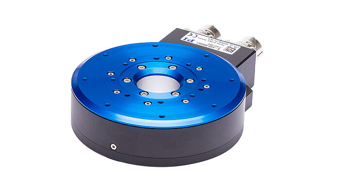
Our direct drive rotary tables provide high torque and are easy to integrate. They contain high-energy magnets in a simplified mechanical design and drive loads directly without the need for a transmission mechanism or gearbox. It allows customers to build them right into a drive system for flexible placement and integration with cooling pipes and cables, for example.
We supply a wide range of frameless motors, and our adjustable motors include an optical encoder, scale, bearing and housing. Given our selection, it can be challenging to choose the best direct drive motor for your project. Our engineers prefer to help you find the right rotary table for your requirements.
Our most popular rotary motor, the AXD series is characterized by a slim, compact "pancake" design with high peak and continuous torque despite the motor"s quite small form factor.Direct drive and brushless motor
The ACD series is a set of ironless rotary tables. This motor is cogging-free and features high-resolution optical encoder feedback and low speed variability. This permanent magnet motor is equally suited for either low or high speed applications.Zero cogging coreless motor

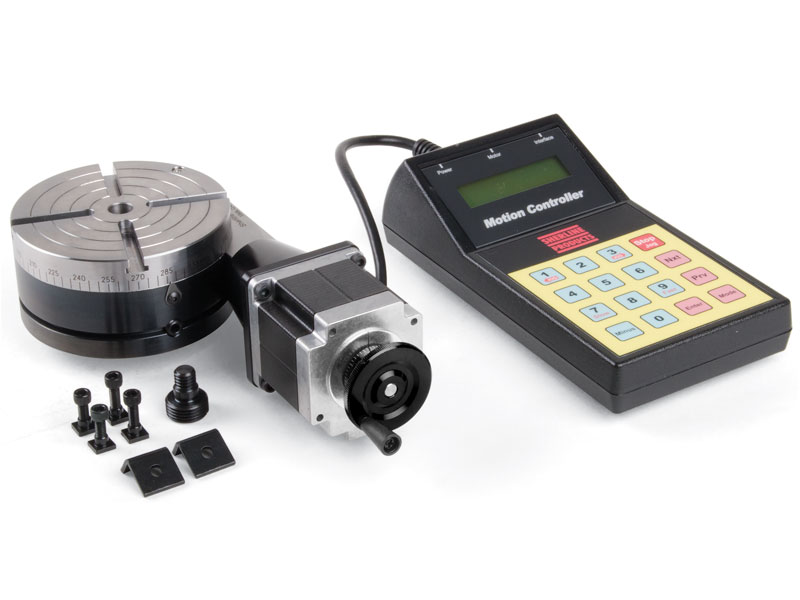
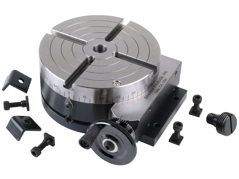
A rotary table used in conjunction with a mill allows a machinist to produce virtually any part they can design. Sherline’s rotary table is a precision piece of equipment that has been designed to work with their vertical milling machines. However, it can be used on any mill whenever the small 4-inch size would be an advantage. The only limits are size, not complexity.
The table is 2″ high and 4″ (100mm) in diameter. The main components have been machined from solid bar stock steel, and the complete unit weighs seven pounds. The table has been engraved with a laser, giving sharp and precise lines every 5°, numbered every 15°. These lines are calibrated with the 72-tooth worm gear that is driven by the handwheel. The handwheel is divided into 50 parts, making each line on the handwheel 1/10°. This allows a circle to be divided into 3600 increments without interpolation. Seventy-two revolutions of the handwheel rotate the table one revolution.
The rotary tables can hold more weight when they are not under a continuous load. Click on the Video tab above to see examples of different weights and uses for our rotary tables.
The table T-slots are identical to those used on the Sherline mill and lathe, making the vast line of Sherline tooling available for use with this product. Two hold-down clamps and T-nuts are provided with the table. Also included is an adapter that allows Sherline’s 3- and 4-jaw chucks to be screwed directly to the rotary table. An optional right-angle attachment is available (P/N 3701) to mount the table in the vertical position to increase its versatility further. With the table mounted vertically, an optional adjustable right-angle tailstock (P/N 3702) can be mounted to the mill table. It is used to support and stabilize the other end of long work held in a chuck or otherwise attached to the rotary table.
Years ago, before I learned CNC, I owned a Phase II 8″ horizontal/vertical rotary table that I purchased from Kap Pullen’s Getmachinetools.com store. He has them at a good price, BTW, and he’s a darned nice fellow to deal with as well as being a frequent HSM contributor. Anyway, its a nice little table, but I hadn’t done a whole lot with it for quite a while after purchasing it. As is so often the case, one day, a project landed on my doorstep and I was glad to have it.
Before I could get started, however, I had to make some accessories for it. Basically, I needed some T-Nuts to fit the table, as well as a little fixture that makes it easy to hold a plate up off the table through a hole in the center so you can machine it. The latter, what I call a “plate machining fixture”, was inspired by something similar I saw the Widgitmaster of CNCZone fame using to make Dremel clamps for his mini-router:
I turned the round spigot using the 4-jaw on the lathe. I’m making the fixture out of MIC-6 aluminum plate, which is pre-ground very flat on the sides. This is a 5 inch by 3 inch piece. I’ve clamped it to the rotab using my T-nuts and the regular mill clamps and step blocks. It is sitting on parallels to make sure I don’t cut into the table. You can also see how I’ve clamped the rotary table to the mill table using a big cast iron V-block I have. You can never have to many blocks with precision faces hanging around!
Having a 4-jaw chuck on your rotary table is mighty handy! Because it’s a 4-jaw, you can dial in the workpiece by adjusting the jaws until it is perfectly concentric with the table’s axis of rotation. The best way is to make an adapter plate that attaches to the back of the chuck in the same way that your lathe does so you can exchange lathe tooling with the rotab. Here is an example:
For the example, the chuck is threaded onto the adaptor plate, and then the holes in the adapter plate’s flange are used to bolt down to T-nuts on the table.
In my case, I bought a 4-jaw from Shars brand new, and simply drilled some through-holes in the chuck to mount to the table directly without an adapter plate:
First, you want to make sure your part is properly centered on the table. To do that, I clamp the table down on the mill table (no special place is needed), put my Indicol indicator holder on the mill spindle, and find some round feature on the part to indicate on. For example, on the plate milling fixture above, indicate on the round boss, or on the center hole. Spin the table and bump the part in until spinning the table doesn’t move the indicator.
Second, locate the center of rotation directly under the mill spindle. You can simply use the X and Y table handwheels to do this. Use that Indicol to indicate off of a circular feature you want centered under the spindle. Turn the indicol around on the spindle and adjust the handwheels until the indicator stays put relative to the spindle position. A Blake Coaxial indicator will make this last even simpler.
When you’re rounding partially by cranking a part around on the rotary table, it’s really easy to go a little too far and screw things up. The answer is to drill the end points to make the exact stopping point on the rotab a lot less sensitive:
Centering with a Blake indicator is really fast, but what if you don’t have a Blake, or worse, what if your mill is too small to accomodate one? Here is a nice solution I found on a German site. This fellow has made an ER collect fixture for his rotary table, and has taken care that when installed on the table, the axis of the collet is aligned with the table’s axis. He can then place a dowel or other straight pin in the collet and line up until it will go into a similarly sized collet on the spindle. Nice trick! It’s similar to how Widgitmaster showed me to align a drill chuck on a QCTP to the lathe centerline with a dowel pin held in the lathe chuck.
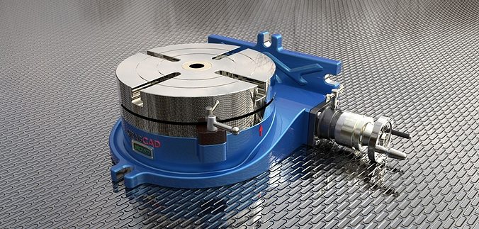
Cameron rotary tables range from 27 1/2 in to 60 1/2 in and feature a large oil capacity that adds to the unit"s durability. The rotary table includes a forged-steel fabricated housing and a heat-treated forged-steel turntable. Each rotary table is supplied with spiral-bevel, induction-hardened gears and two independent ratchet-type locks, with lever access from the top to lock the table in position.

A rotary table can optionally be controlled by the robot so that the path point to be approached in each case in the USER coordinate system is in the ZX plane of the BASE coordinate system with Y = 0. In this way, the robot"s degrees of freedom can be extended to include movement in the Y direction. See also chapter Controlling a transport device by the robot. The "USER_ControlledByRobot" coordinate system must be set in the SRL program for this purpose.
The example IEC code in chapter Synchronized movement with a rotary table is valid with the exception that the position profile is not transferred to the fbRotaryTable. Instead, the setpoints are read from the fbRotaryTable.lrSetpointPosition property and are used to drive a MultiMotion tracking axis.
For prepositioning the rotary table, the method AdjustToPoseWithProfile() of the function block ConveyorOrRotaryTable can be used. During positioning, the coordinate system "USER_ControlledByRobot" must not be set in the SRL program for this rotary table. The robot must be in "BASE" during positioning, for example. Run the following sample code, for example in the User_PRG.HighPrio task.
The rotary table is positioned in such a way that the point with the coordinates X = alrPose[1], Y = alrPose[2] in the USER coordinate system after positioning in BASE coordinates has the coordinate value Y = 0 and is located between the robot base and the center of the rotary table. Positioning is performed by the shortest distance. Positioning starts at the rising edge of xStart. The input variable must remain "TRUE" until the end of positioning and must then be called with "FALSE" as soon as USER_ControlledByRobot is set again. The function block returns "TRUE" once positioning has been completely executed.
When creating the application, it is also necessary to pay attention to the following properties:A change from/to the USER coordinate system of a rotary table is only possible via "BASE".
The rotary table is always aligned automatically in such a way that the position to be approached is on the side of the rotary table facing the robot.
To change to or from the USER coordinate system, the rotary table must be in idle state if the robot cannot execute a compensation movement in Y-direction.
The "BackToPath" function does not work with the current version of the software because the rotary table is not automatically repositioned to the appropriate position to continue the path smoothly.
Its dirt simple, you just rotate it till you get the index pulse and your away again, No index pulse setup? there"s no more to it than if your adjustable dial slipped on a manual rotary table. Just pick up a known features location, zero it or type in the angle and your off again, easy :-)
IT"s akin to buying a random slot drill otherwise, not knowing if its big enough or small enough to cut the slot you need. Gezz, some people just love to invent issues were they don"t exist. 30-40 years ago this stuff use to be hard. Now a days it really is not thanks to standardized stuff. Hardest bit is going to be mounting it to the rotory table + keeping it clean and dry.
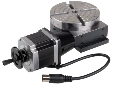
The stepper motor will have to be sized for your application. I used a small 3 rotary table and dont plan on using it for anything other than indexing so a high torque NEMA17 did the job. If youre working with a larger rotary table or want to be able to use it as a 4th axis in the mill you will want at least a NEMA23 size motor. You will have to reach out to the forum for help with selection.


 8613371530291