
dividing head vs rotary table factory

Rotary tables are mounted horizontally, and most can also be mounted vertically. In both cases only at 90° to the mill table. A Dividing Head is always vertical, but can be tilted through 90°.
Dividing heads are always fitted with "indexing plates" (holed wheels and clock hands), allowing a wide range of angles to be turned. The indexing mechanism can do intermediate angles. Rotary tables can be fitted with indexing plates as an accessory, but usually the number of angles supported is limited compared to a dividing head. (A generalisation. And, because rotary tables do all common angles, the limitation may not matter.)
Rotary tables are more convenient for general work because most jobs are mounted at 90° or 180° relative to the milling table. Possibly more robust than a dividing head for rough work. When close accuracy isn"t needed, jobs can be spun rapidly by the rotary table without cranking the handle - a time saver. When accuracy is needed the handle and worm are engaged. Usually there"s a vernier scale sufficiently accurate for most work. The handle is also relatively fast because most simple angles can be produced with it. For example, easy to crank from 0, 60, 120, 180, 240, 300, 0 to cut a hexagon head. Unfortunately not all angles are "simple"!
Indexing plates are so awkward that driving a Rotary Table with a stepper motor and microcontroller is popular. You simply tell the controller how many divisions are needed, press "Go", and the computer does the rest. Apart from reducing brain strain and automating a tedious task, the computer eliminates most mistakes. Computers don"t get sums wrong, have excellent memories, and are hard to distract! Also, a computer and stepper motor will do a good job of angles too complicated for the Indexing plates.
Generalising again, I suggest most people, most of the time, only need a rotary table. I see Dividing Heads as specialist tools and have never felt the need for one. For the same reason I drive an ordinary small car rather than a Land Rover. The closest I get to off-road driving is a supermarket car park! You might live on a farm...
Unless there"s a specific reason for needing a Dividing Head, I wouldn"t spend money on one. My rotary table is used a lot, in contrast a Dividing Head is only "nice to have".

Dividing heads allow you to divide a circle into equal fractions conveniently. Anything that involves regular action around a circle is a candidate for a dividing head.
A rotary table has no stops so it is not convenient to do large numbers of things at equal intervals because you would have to painstakingly determine the interval. Also, the rotary table does not divide the circle. For example, if you were making 13 equally spaced operations using a rotary table you would have to calculate some wierd angle for each operation and dial it in--a tedious process. For example, here are the 13 angles for a circle division:
Do you want to manually set each of these values? Have fun doing that. Now, imagine doing it for 53 divisions. You will be there all night. Not only that, the error will be a lot more than a dividing head.

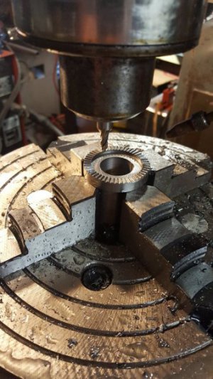
I have used it in the vertical position to cut a 107 tooth gear which isn"t covered by any of the dividing head wheels I"ve got. I set up an excel spreadsheet with the angle required for each tooth which isn"t as easy as it sounds as the rotary table is calibrated in degrees/minutes/seconds rather than decimal degrees so it took a bit of figuring out how to do it.

I think as rotary table with index plates and a tailstock might be a bit more versatile than a dividing head. You can use its flat table to clamp projects down on,like a face plate. You can add a chuck. You can still cut gear teeth with the dividing attachment. A universal index head can tilt,but a rotary table can too,if you mount it on a tilting table. Less rigid on a tilting table,but I like using the flat table better than other short comings it might have.
These days it"s pretty trivial to create a spreadsheet to figure out the required degrees/minutes/seconds for some arbitrary number of divisions n, so it"s not all that big a deal to use a rotary table for dividing. A dividing head is, as others say, probably a bit more convenient both in ease of dividing oddball numbers of divisions and in less mass to get in the way of what you"re machining...but a rotary table will be more flexible. If you want to substitute for a dividing head, be sure to get a horizontal/vertical rotary table, as you"ll want "vertical" mode for dividing (and making gears).
If the rotary table has a Morse #3 center hole (or whatever), in vertical mode you could probably use Morse taper collets for workholding, which might be pretty handy. The only thing is, as hinted above, in vertical mode there may be a lot of rotary table in the way of what you"re trying to machine, if you need to get in close. It"s do-able, but you may to need to be a bit creative in workholding to arrange necessary clearance to get the tool where you need it.

This plate can be used either directly, or through a geared dividing mechanism. In direct indexing the workpiece and plate rotate in a 1-to-1 ratio, and holes are used directly. That is, a plate with 12 holes can divide the workpiece into 2, 3, 4, 6, or 12 equal segments. A dividing head incorporates an internal gear ratio (usually 40:1, 60:1, or 90:1) with the same plates. In doing so, the dividing head enables many more combinations than just direct indexing.
For example, imagine a plate with 15 equally-spaced holes and a dividing head with a 40:1 gear reduction. In direct indexing, a workpiece could be divided into 3, 5, or 15 equal segments. Using the dividing head, the same workpiece could be divided into 2, 3, 4, 5, 6, 8, 10, 12, 15, 20, 25, 30, 40, 50, 60, 75, 100, 120, 150, 200, 300, or 600 segments. Essentially, the dividing head acts as if it’s a direct indexer with 600 holes; 15 holes in the actual plate * 40:1 gear ratio. Let’s look at how some of these combinations are possible.

If your table has a ratio of 90:1 then you will have to turn the dial 90 turn to make the table go around once. That means that you divide 360 degrees by 90 turns and you get 4 degrees per turn. Simple enough.
So here is what you do. This is where the plates come in! This example is easy but the theroy is the same. You only need a plate with two holes but since there is no such thing you will use any plate that the row of holes you want to use will divide by 2 since you need half turns. Set your index arms so that the pin on your arm falls inside the dividing arms. Set them so that you can find the next hole of the same count. IE: If you used a 24 hole plate then you will have 12 holes between the arms thus giving you half turns each time you index.

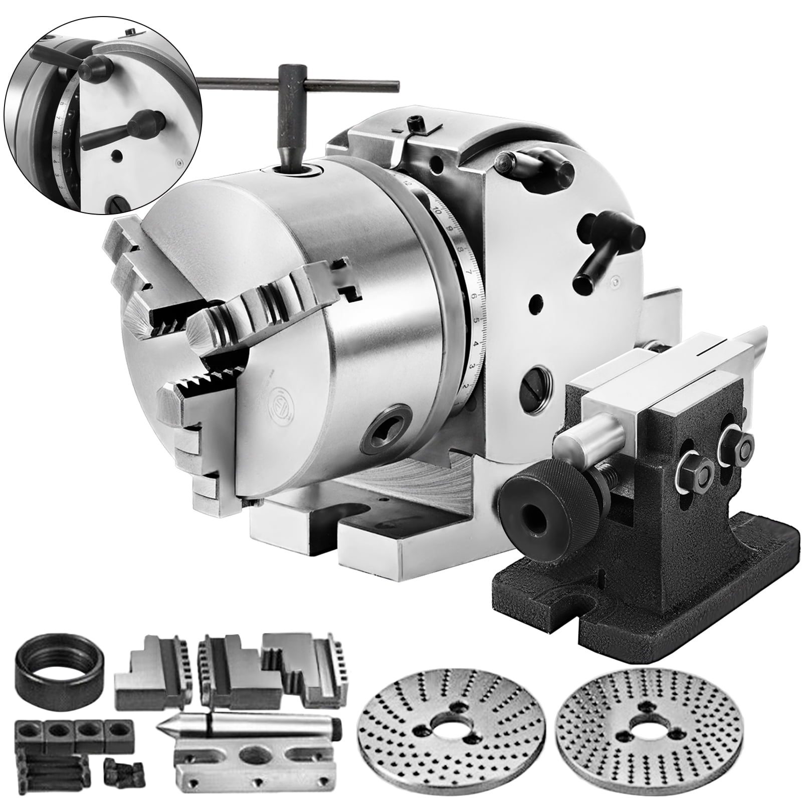
The indexing plate is a machine tool accessory that holds the workpiece on the chuck or between two pinnacles and rotates, indexing and positioning it. Plate connected with rotary indexing table is in Diameter: 7"/180mm and Thickness: 0.47"/12mm, good for rotary tables in Model HV-8, HV-10, HV-12, HV-14, TS200, TS250, TS320, TS400. Perfect to use with dividing head for milling table.

A rotary table is a precision work positioning device used in metalworking. It enables the operator to drill or cut work at exact intervals around a fixed (usually horizontal or vertical) axis. Some rotary tables allow the use of index plates for indexing operations, and some can also be fitted with dividing plates that enable regular work positioning at divisions for which indexing plates are not available. A rotary fixture used in this fashion is more appropriately called a dividing head (indexing head).
The table shown is a manually operated type. Powered tables under the control of CNC machines are now available, and provide a fourth axis to CNC milling machines. Rotary tables are made with a solid base, which has provision for clamping onto another table or fixture. The actual table is a precision-machined disc to which the work piece is clamped (T slots are generally provided for this purpose). This disc can rotate freely, for indexing, or under the control of a worm (handwheel), with the worm wheel portion being made part of the actual table. High precision tables are driven by backlash compensating duplex worms.
The ratio between worm and table is generally 40:1, 72:1 or 90:1 but may be any ratio that can be easily divided exactly into 360°. This is for ease of use when indexing plates are available. A graduated dial and, often, a vernier scale enable the operator to position the table, and thus the work affixed to it with great accuracy.
Rotary tables are most commonly mounted "flat", with the table rotating around a vertical axis, in the same plane as the cutter of a vertical milling machine. An alternate setup is to mount the rotary table on its end (or mount it "flat" on a 90° angle plate), so that it rotates about a horizontal axis. In this configuration a tailstock can also be used, thus holding the workpiece "between centers."
With the table mounted on a secondary table, the workpiece is accurately centered on the rotary table"s axis, which in turn is centered on the cutting tool"s axis. All three axes are thus coaxial. From this point, the secondary table can be offset in either the X or Y direction to set the cutter the desired distance from the workpiece"s center. This allows concentric machining operations on the workpiece. Placing the workpiece eccentrically a set distance from the center permits more complex curves to be cut. As with other setups on a vertical mill, the milling operation can be either drilling a series of concentric, and possibly equidistant holes, or face or end milling either circular or semicircular shapes and contours.
with the addition of a compound table on top of the rotary table, the user can move the center of rotation to anywhere on the part being cut. This enables an arc to be cut at any place on the part.
Additionally, if converted to stepper motor operation, with a CNC milling machine and a tailstock, a rotary table allows many parts to be made on a mill that otherwise would require a lathe.
Rotary tables have many applications, including being used in the manufacture and inspection process of important elements in aerospace, automation and scientific industries. The use of rotary tables stretches as far as the film and animation industry, being used to obtain accuracy and precision in filming and photography.
A rotary table is similar to an indexer, but it is designed to hold objects to its surface with t-slot clamps. They are fairly inexpensive (check your MSC catalog), but the suckers can get heavy. An indexer generally uses a collet system to hold the material. It is mostly for drilling hole patterns in round materials, and they can be quite expensive. I have both, and I use my rotary table about 20 times more than my indexer. RE: Difference between rotary table and indexer
Something else to think about if you have a specific use in mind for either. You might be able to pick up a dividing attachment that installs on a rotary table allowing the user to select the number of stops in a revolution of the table. I used to work for a company that made it"s own dividing attachments for their line of rotary tables and they were quite reliable. It depends on your application. RE: Difference between rotary table and indexer
A table top, not necessarily circular in shape, is mounted on a rotating device. The table has fixtures mounted to it so that, as the table rotates, a fixture is presented to a machine of some sort. At the machine, the parts are operated on. Then they index to the next station.
The rotator can be (typically) a cam-operated gizmo with motor to rotate the table a certain number of degrees on each cycle. Sometimes I have seen the rotator device something like a big stepper motor, to achieve a much more flexible positioning.
Indexing tables are a type of rotary table. An indexing table has ability to index to differnt degrees of rotation via mechanical stops (or electro mechanical).
In the CNC world, it"s a matter of terminology were there are rotary tables and rotary indexers controlled by the machine. In a 4-axis CNC machine the 4th axis is the rotary table or indexer. Generally the main difference is that the indexer is programmed to lock into position before machining. Rotary tables are programmed to move simultaneously while the machine cuts. Most indexers can be used like a rotary table and visa versa. Also, small units like those who use 5C collets are sometimes referred to as indexers while larger units are called tables.
In the manual machine world, the operator controls the rotary table and indexer. There are many types of indexing devices like those already mentioned, such as dividing heads that use plates with holes for precise location. Rotary tables allow machining while tuning the table. Some rotary tables have a cross slide table mounted on top for positioning of the work piece.
Nice input, That is exactly what I was getting at. I have used small rotary tables with 5C collets and with chucks. The mount has little to do with it.
When you need to rotate a part when cutting, use a rotary table. Most of these either manual or CNC will have a worm gear drive. An indexing table or head is designed to move an accurate amount and be locked. In the manual world a spindle is positioning by hand or worm gear and a plate and pin are used to stop the rotation in a specific place. In the CNC world several different methods can be used to rotate the spindle and either a shot pin or a toothed coupling is used to lock the rotation. Most indexing devices do not allow for machining when rotating and will handle greater off axis torque from milling or drilling. RE: Difference between rotary table and indexer
A superspacer typically has a three-jaw chuck for holding the work and a spur gear with 48 teeth providing 7.5 degree increments and a spring loaded shot-pin tooth to engage the gear and lock it into rotary position. Also slotted plates can be attached to allow the shot-pin to only engage at specific rotation angles such as every 45 degrees or every 90 degrees.


 8613371530291