
dividing head vs rotary table free sample

Dividing heads allow you to divide a circle into equal fractions conveniently. Anything that involves regular action around a circle is a candidate for a dividing head.
A rotary table has no stops so it is not convenient to do large numbers of things at equal intervals because you would have to painstakingly determine the interval. Also, the rotary table does not divide the circle. For example, if you were making 13 equally spaced operations using a rotary table you would have to calculate some wierd angle for each operation and dial it in--a tedious process. For example, here are the 13 angles for a circle division:
Do you want to manually set each of these values? Have fun doing that. Now, imagine doing it for 53 divisions. You will be there all night. Not only that, the error will be a lot more than a dividing head.

Rotary tables are mounted horizontally, and most can also be mounted vertically. In both cases only at 90° to the mill table. A Dividing Head is always vertical, but can be tilted through 90°.
Dividing heads are always fitted with "indexing plates" (holed wheels and clock hands), allowing a wide range of angles to be turned. The indexing mechanism can do intermediate angles. Rotary tables can be fitted with indexing plates as an accessory, but usually the number of angles supported is limited compared to a dividing head. (A generalisation. And, because rotary tables do all common angles, the limitation may not matter.)
Rotary tables are more convenient for general work because most jobs are mounted at 90° or 180° relative to the milling table. Possibly more robust than a dividing head for rough work. When close accuracy isn"t needed, jobs can be spun rapidly by the rotary table without cranking the handle - a time saver. When accuracy is needed the handle and worm are engaged. Usually there"s a vernier scale sufficiently accurate for most work. The handle is also relatively fast because most simple angles can be produced with it. For example, easy to crank from 0, 60, 120, 180, 240, 300, 0 to cut a hexagon head. Unfortunately not all angles are "simple"!
Indexing plates are so awkward that driving a Rotary Table with a stepper motor and microcontroller is popular. You simply tell the controller how many divisions are needed, press "Go", and the computer does the rest. Apart from reducing brain strain and automating a tedious task, the computer eliminates most mistakes. Computers don"t get sums wrong, have excellent memories, and are hard to distract! Also, a computer and stepper motor will do a good job of angles too complicated for the Indexing plates.
Generalising again, I suggest most people, most of the time, only need a rotary table. I see Dividing Heads as specialist tools and have never felt the need for one. For the same reason I drive an ordinary small car rather than a Land Rover. The closest I get to off-road driving is a supermarket car park! You might live on a farm...
Unless there"s a specific reason for needing a Dividing Head, I wouldn"t spend money on one. My rotary table is used a lot, in contrast a Dividing Head is only "nice to have".

I have used it in the vertical position to cut a 107 tooth gear which isn"t covered by any of the dividing head wheels I"ve got. I set up an excel spreadsheet with the angle required for each tooth which isn"t as easy as it sounds as the rotary table is calibrated in degrees/minutes/seconds rather than decimal degrees so it took a bit of figuring out how to do it.

These days it"s pretty trivial to create a spreadsheet to figure out the required degrees/minutes/seconds for some arbitrary number of divisions n, so it"s not all that big a deal to use a rotary table for dividing. A dividing head is, as others say, probably a bit more convenient both in ease of dividing oddball numbers of divisions and in less mass to get in the way of what you"re machining...but a rotary table will be more flexible. If you want to substitute for a dividing head, be sure to get a horizontal/vertical rotary table, as you"ll want "vertical" mode for dividing (and making gears).
If the rotary table has a Morse #3 center hole (or whatever), in vertical mode you could probably use Morse taper collets for workholding, which might be pretty handy. The only thing is, as hinted above, in vertical mode there may be a lot of rotary table in the way of what you"re trying to machine, if you need to get in close. It"s do-able, but you may to need to be a bit creative in workholding to arrange necessary clearance to get the tool where you need it.

If your table has a ratio of 90:1 then you will have to turn the dial 90 turn to make the table go around once. That means that you divide 360 degrees by 90 turns and you get 4 degrees per turn. Simple enough.
So here is what you do. This is where the plates come in! This example is easy but the theroy is the same. You only need a plate with two holes but since there is no such thing you will use any plate that the row of holes you want to use will divide by 2 since you need half turns. Set your index arms so that the pin on your arm falls inside the dividing arms. Set them so that you can find the next hole of the same count. IE: If you used a 24 hole plate then you will have 12 holes between the arms thus giving you half turns each time you index.

I used a scrap riser to mill a custom knob with 17 flutes as an example, because most traditional manual rotary tables and dividing heads struggle with dividing prime numbers.
I needed two large holes in plates, 46mm and 40mm. I mounted the plates on the rotary table, set the indexer to continuous run and slowly lowered the cutting bit. This saved me from having to buy 2 different size hole saws that I might never use again.
The mill rotary table is one of the main accessories of milling machine. As a precision work positioning device, it is widely used for indexing drilling, milling, circumferential cutting, boring, etc. The rotary turn table for milling machine is made from casting with high quality, can work with a set of dividing plate.
Both vertical and horizontal with two functions. Circle cutting, indexing drilling, milling and more complicated work are possible when the vertical position of the table is used together with the tail part.
Three dividing plate set(Plate "A" - 15, 16, 17, 18, 19, 20 Plate "B" - 21, 23, 27, 29, 31, 33 Plate "C" - 37, 39, 41, 43, 47, 49). A set of wrench and screws are free for you with your installation.

The dividing head is essentially a horizontal (though sometimes tiltable) shaft with a wormwheel on it that can be driven round by means of a worm. The shaft has various means of holding a workpiece.
This may seem very similar to a rotary table. It is different in that there is no table to mount the workpiece on. Instead it is possible to mount a center in the shaft or mount a chuck onto it. Usually dividing heads are supplied with a tailstock. This is essential when using a center with the dividing head. It can also be very useful for supporting the workpiece when using the chuck. Most professional dividing heads, regardless of size, usually have a ratio of 40:1 between turning the handle and the shaft rotating. Strangely, smaller ones often have higher ratios, often 90:1.
On all dividing heads the worm is turned by means of a handle. Each turn of the handle can be divided by means of a dividing plate that contains a number of rings each with a different number of holes in it. The handle has a pin that can be moved to fit the holes in any one of the rings of holes.
Dividing heads can be split into three types. These are closely related to their size and complexity. These are the “plain”, the semi-universal and the universal. There is also a rather rare type that swivels in the horizontal plane.
In this case, firstly the shaft can be tilted. Secondly, and what makes the universal dividing head universal is that it has an auxiliary input at the back of it. When this is turned it rotates the dividing plate.
In the case of the universal dividing head the dividing plate can either be fixed or it can be rotated by turning the auxiliary drive shaft. When used as a plain dividing head the dividing plate is locked in position. When used for helical milling the dividing plate is unlocked and can be turned by means of the auxiliary input.
On all dividing heads the worm is turned by means of a handle. The handle either contains a retractable pin or the other end of the handle contains a pin that can be locked into a hole in a dividing plate.
This plate has several rings of holes spaced equally around the plate. The number of holes in each ring is different. The indexing pin, whether it is in the handle or separate, can be set so the pin will fit in any hole in any one ring of holes on the division plate. Using this means that movement of the spindle on the dividing head can be made by any number of spaces.
This handle might appear to be just a handle. But when using a dividing head to make, for example, a spur gear, there are a large number of movements the operator must make using this handle. The handle shown above is just about as good as possible. The features to watch out for are:
The dividing plate is the key to dividing the circle. Often a dividing head is supplied with three dividing plates. Each plate contains a number of rings of holes. This means that one turn of the handle can be divided into the number of holes in the particular ring. Working this out is covered under“Dividing the circle”.
On some dividing plates the holes are only drilled to nearly halfway through the plate. There is another set of rings of holes on the other side of the plate so the plate can be fitted and used either way round.
When the dividing plate is fitted properly all of the “zero” holes will be in line and will be vertically above the shaft of the handle. Usually, next to each of the zero holes, is stamped the number of holes in the ring.
As a completely separate feature a dividing head often has an indexing feature that is separate from the division plate. This means that the shaft of the dividing head can be used as a simple index head.
In the example above, the holes for indexing are just to the left of the division plate. The indexing pin is the black knob on the top of the dividing head. On larger dividing heads, where the wormwheel is totally enclosed there may be a completely separate plate that can be fitted on the main shaft just for indexing.
On dividing heads that can be tilted, the shaft the handle is mounted on is fitted eccentrically in a sleeve that can be rotated. This not only enables the spacing between the worm and wormwheel to be adjusted it can also be used to disengage the handle from the shaft driving the worm. The fig. shows the arm for controlling the engagement of the worm and worm wheel.
In the above photo, the dividing plate and the lower gear are permanently connected together. The handle which is to the left of the dividing plate is connected to the shaft which is fitted with the worm. This is inside the dividing plate/bottom gear assembly. When the worm is disengaged this shaft moves downwards so that the bottom gear in the photo is disconnected from the gear above it. This top gear is is connected to the auxiliary input. In this situation the dividing plate etc. is free to rotate. When the worm is disengaged what happens here has no impact on what is happening to the main shaft.
When the worm is engaged The diving plate can be used in one of two ways. In the first it is locked. This is done by a small tab which is held in place by the cap screw at the top of the preceding photo. This tab fits in a slot on the back of the dividing plate.
Alternatively, when the auxiliary input is in use this tab is withdrawn. The auxiliary input drives the top gear. The worm is engaged with the wormwheel. So the top gear drives the bottom gear. This rotates the dividing plate. The pin on the handle is in one of the holes on the dividing plate. As this handle rotates so does the worm and hence the wormwheel and workpiece.
The spindle always has a hole all the way through it. At the front end, the spindle, on larger dividing heads, often has a taper and/or a thread or some other means of holding a chuck.
On larger dividing heads the spindle has, at the back end, a thread so that an extension shaft can be screwed into it. This enables the dividing head spindle to be driven directly, but this will only work if the worm has been disengaged from the main shaft.Though this is a rather unusual feature it is, surprisingly, one that could be easy to implement on any homemade dividing head.
Rather like the rotary table the dividing head always has some means of locking the spindle in the same way as the table can be locked on the rotary table. And it is used in a similar way. If the workpiece is being machined between two points the lock has to be off. If the workpiece is to be machined at one point, as when cutting a tooth on a spur gear, the spindle should be locked.
It might seem odd but dividing heads can be either left or right handed. That is, with the dividing plate facing the user, the nose of the spindle can be either to the left of the dividing head or to its right.
This is significant is when a universal dividing head is driven by the leadscrew on the milling table. If the auxiliary input is on the left then access to the leadscrew will have to be on the left. If the table has power feed at one end then, often, the dividing head will have to have its auxiliary input at the other end of the table.
A key feature of a dividing head is the center height. This is the height between the axis of rotation when the shaft is in the horizontal position and the milling table. In general, the higher the center height the better. But this of little use if the largest diameter of workpiece will not fit between the milling table and the bottom of the cutter being used.
Even more important is that it is too big if it cannot be safely and easily moved on or off the milling table. The weight goes up far faster than the center height. A center height of 100mm could easily be the most that many model engineers could safely manage.
If the dividing head is in the horizontal position, the maximum diameter workpiece it can hold is bit less than twice its center height. This can be increase by mounting the dividing head (and the tailstock if used) on raising blocks. But whether this is useful depends on whether there is still enough space between the cutter and the milling table.
In the figure another use is shown. In this case the dividing head is raised so its axis is near the height of the spindle when it is nearly horizontal.
Universal dividing heads have an auxiliary input at the back of the head. This is used for helical milling. This is where, as the milling table moves along, the leadscrew is used, via a gear train, to rotate the workpiece being held by the dividing head.
Notice that the exposed part of the auxiliary input is only the near end of the shaft. The large diameter bit is a boss. This is used for fitting the quadrant arm onto the dividing head.
Often when the auxiliary input is being used this will involve a gear train. The gears are mounted on an arm that fits a boss round the shaft of the auxiliary input. An arm like this is often used for a similar purpose on a lathe. On the lathe it often is designed to rotate through 90° and so is known as a quadrant arm. On a dividing head it is usually just a straight arm. It rotates simply by the angle it is fitted onto the boss on the auxiliary input of the dividing head.
A gear train often starts with a gear on one shaft such as the end of the leadscrew. At the other end it is often on the auxiliary input to the dividing head.

While a spin indexer might give us more flexibility, for creating simple divisions, a 3D printer can be extremely useful to make an object we can use as the reference for indexing. In Figure 3, we have used a 3D-printed octagonal part to create a collar for some 12 mm brass bar stock. We quickly designed and printed the octagonal collar with the inner diameter being a press fit onto the brass bar stock. Using the faces of the printed octagon, we can rotate the circular bar eight times and perform an operation on each face. In this instance, we have used a precision vice to clamp the workpiece. We set the position with the 3D-printed collar using a small riser block between the milling table and the collar, and then milled the small keyways into the bar stock, repeatedly indexing the part by resetting the piece to the next face of the octagonal collar.
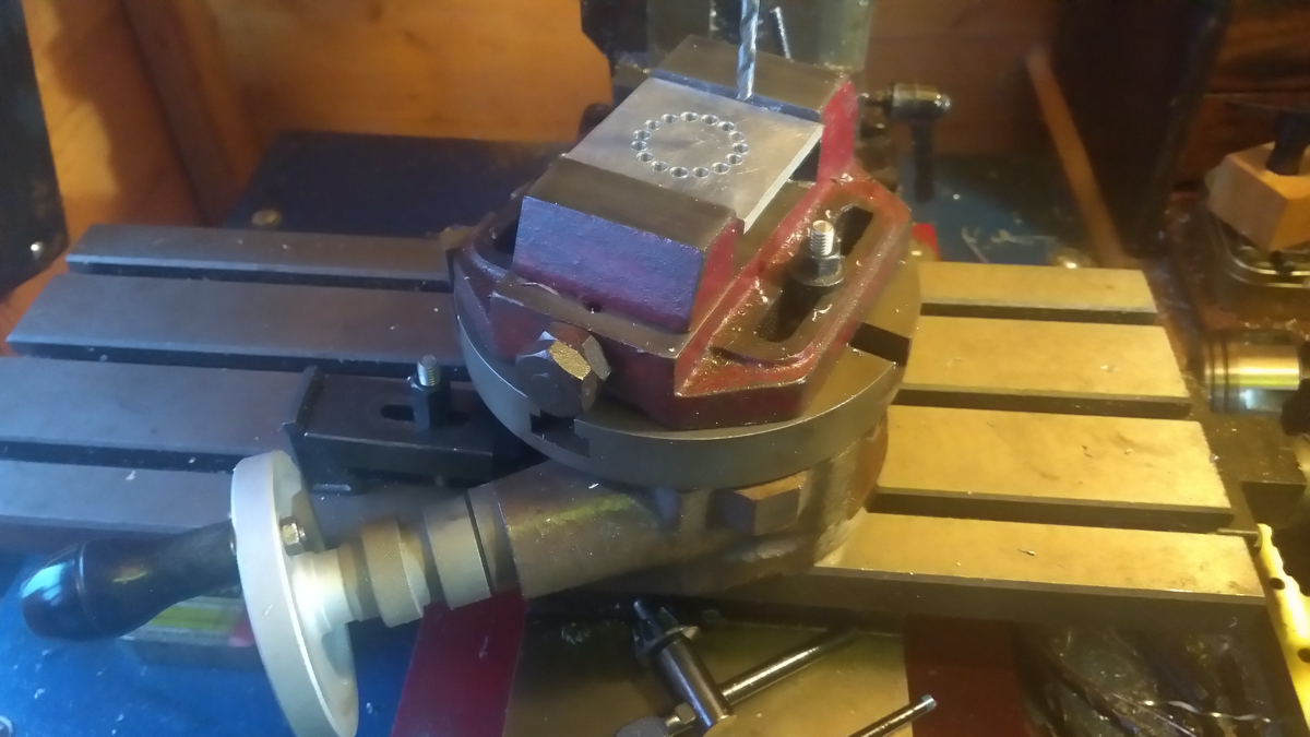
Another workshop item that is a midpoint tool (and not as costly as a dividing head) is a rotary table. A rotary table is a milling accessory that is primarily designed for machining arc paths on the manual milling machine. However, as it can rotate a workpiece through a known number of degrees, it can also be used for dividing purposes. It consists of a circular worktable which is rotated by a gear and worm-gear arrangement attached to a winding handle. It’s a common project for machinists to convert rotary tables into forms of dividing head by adding dividing plates but, even in its standard form, the rotary table can be useful for dividing. In Figure 4, we can see that we have used the rotary table and a vice to create a circle of 15 equidistantly placed holes around a pitch diameter. Simply dialling the table around 24 degrees per index using the graduated dial moves the workpiece to the next position, and a grub-screw on the table acts as a lock to clamp the table while performing the drilling operations.
With imagination, hackspace-type tools like laser cutters, 3D printers, and CNC machines can be used to create all kinds of tools that can help with dividing tasks. Printing or cutting dividing plates that can be attached to spindles can enable us to create dividing heads, and we have seen many examples of 3D-printed gears being used to index workpieces.
Any number of marks that’s a factor of 60 can be made by starting with the gear set to zero at the reference gear lock, and marking the first point and then indexing the assembly around to the desired division. So, for the example of a rocket tube with 4 fins, indexing and marking through the numbers 0, 15, 30, and 45 gives the correct points. Having marked the tube, we can remove it and extend the marks using a piece of aluminium angle to ensure the lines remain straight in relation to the centre point of the tube. While this application is a pretty unusual use case, we hope that it perhaps inspires ideas into how laser-cut or 3D-printed tools can be made that assist dividing tasks in projects. All the files for this particular tool are available here: hsmag.cc/UXcwxP.

I think as rotary table with index plates and a tailstock might be a bit more versatile than a dividing head. You can use its flat table to clamp projects down on,like a face plate. You can add a chuck. You can still cut gear teeth with the dividing attachment. A universal index head can tilt,but a rotary table can too,if you mount it on a tilting table. Less rigid on a tilting table,but I like using the flat table better than other short comings it might have.


 8613371530291