
diy rotary table free sample
The stepper motor will have to be sized for your application. I used a small 3 rotary table and dont plan on using it for anything other than indexing so a high torque NEMA17 did the job. If youre working with a larger rotary table or want to be able to use it as a 4th axis in the mill you will want at least a NEMA23 size motor. You will have to reach out to the forum for help with selection.
Years ago, before I learned CNC, I owned a Phase II 8″ horizontal/vertical rotary table that I purchased from Kap Pullen’s Getmachinetools.com store. He has them at a good price, BTW, and he’s a darned nice fellow to deal with as well as being a frequent HSM contributor. Anyway, its a nice little table, but I hadn’t done a whole lot with it for quite a while after purchasing it. As is so often the case, one day, a project landed on my doorstep and I was glad to have it.
Before I could get started, however, I had to make some accessories for it. Basically, I needed some T-Nuts to fit the table, as well as a little fixture that makes it easy to hold a plate up off the table through a hole in the center so you can machine it. The latter, what I call a “plate machining fixture”, was inspired by something similar I saw the Widgitmaster of CNCZone fame using to make Dremel clamps for his mini-router:
I turned the round spigot using the 4-jaw on the lathe. I’m making the fixture out of MIC-6 aluminum plate, which is pre-ground very flat on the sides. This is a 5 inch by 3 inch piece. I’ve clamped it to the rotab using my T-nuts and the regular mill clamps and step blocks. It is sitting on parallels to make sure I don’t cut into the table. You can also see how I’ve clamped the rotary table to the mill table using a big cast iron V-block I have. You can never have to many blocks with precision faces hanging around!
Having a 4-jaw chuck on your rotary table is mighty handy! Because it’s a 4-jaw, you can dial in the workpiece by adjusting the jaws until it is perfectly concentric with the table’s axis of rotation. The best way is to make an adapter plate that attaches to the back of the chuck in the same way that your lathe does so you can exchange lathe tooling with the rotab. Here is an example:
For the example, the chuck is threaded onto the adaptor plate, and then the holes in the adapter plate’s flange are used to bolt down to T-nuts on the table.
In my case, I bought a 4-jaw from Shars brand new, and simply drilled some through-holes in the chuck to mount to the table directly without an adapter plate:
First, you want to make sure your part is properly centered on the table. To do that, I clamp the table down on the mill table (no special place is needed), put my Indicol indicator holder on the mill spindle, and find some round feature on the part to indicate on. For example, on the plate milling fixture above, indicate on the round boss, or on the center hole. Spin the table and bump the part in until spinning the table doesn’t move the indicator.
Second, locate the center of rotation directly under the mill spindle. You can simply use the X and Y table handwheels to do this. Use that Indicol to indicate off of a circular feature you want centered under the spindle. Turn the indicol around on the spindle and adjust the handwheels until the indicator stays put relative to the spindle position. A Blake Coaxial indicator will make this last even simpler.
When you’re rounding partially by cranking a part around on the rotary table, it’s really easy to go a little too far and screw things up. The answer is to drill the end points to make the exact stopping point on the rotab a lot less sensitive:
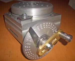
Centering with a Blake indicator is really fast, but what if you don’t have a Blake, or worse, what if your mill is too small to accomodate one? Here is a nice solution I found on a German site. This fellow has made an ER collect fixture for his rotary table, and has taken care that when installed on the table, the axis of the collet is aligned with the table’s axis. He can then place a dowel or other straight pin in the collet and line up until it will go into a similarly sized collet on the spindle. Nice trick! It’s similar to how Widgitmaster showed me to align a drill chuck on a QCTP to the lathe centerline with a dowel pin held in the lathe chuck.

This allow you to make accurate off-axis measurements of your speakers and keeps the pivot point on the font baffle which insures the mic distance remains the same. Using a rotary table allows the measurement mic to stay in a fixed location which minimizes the effects of the room if your making gated measurements. You can also change the design to make it higher if you want to use outdoors.

A rotary table is a precision work positioning device used in metalworking. It enables the operator to drill or cut work at exact intervals around a fixed (usually horizontal or vertical) axis. Some rotary tables allow the use of index plates for indexing operations, and some can also be fitted with dividing plates that enable regular work positioning at divisions for which indexing plates are not available. A rotary fixture used in this fashion is more appropriately called a dividing head (indexing head).
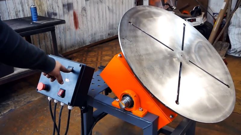
The table shown is a manually operated type. Powered tables under the control of CNC machines are now available, and provide a fourth axis to CNC milling machines. Rotary tables are made with a solid base, which has provision for clamping onto another table or fixture. The actual table is a precision-machined disc to which the work piece is clamped (T slots are generally provided for this purpose). This disc can rotate freely, for indexing, or under the control of a worm (handwheel), with the worm wheel portion being made part of the actual table. High precision tables are driven by backlash compensating duplex worms.
The ratio between worm and table is generally 40:1, 72:1 or 90:1 but may be any ratio that can be easily divided exactly into 360°. This is for ease of use when indexing plates are available. A graduated dial and, often, a vernier scale enable the operator to position the table, and thus the work affixed to it with great accuracy.
Rotary tables are most commonly mounted "flat", with the table rotating around a vertical axis, in the same plane as the cutter of a vertical milling machine. An alternate setup is to mount the rotary table on its end (or mount it "flat" on a 90° angle plate), so that it rotates about a horizontal axis. In this configuration a tailstock can also be used, thus holding the workpiece "between centers."
With the table mounted on a secondary table, the workpiece is accurately centered on the rotary table"s axis, which in turn is centered on the cutting tool"s axis. All three axes are thus coaxial. From this point, the secondary table can be offset in either the X or Y direction to set the cutter the desired distance from the workpiece"s center. This allows concentric machining operations on the workpiece. Placing the workpiece eccentrically a set distance from the center permits more complex curves to be cut. As with other setups on a vertical mill, the milling operation can be either drilling a series of concentric, and possibly equidistant holes, or face or end milling either circular or semicircular shapes and contours.
with the addition of a compound table on top of the rotary table, the user can move the center of rotation to anywhere on the part being cut. This enables an arc to be cut at any place on the part.
Additionally, if converted to stepper motor operation, with a CNC milling machine and a tailstock, a rotary table allows many parts to be made on a mill that otherwise would require a lathe.
Rotary tables have many applications, including being used in the manufacture and inspection process of important elements in aerospace, automation and scientific industries. The use of rotary tables stretches as far as the film and animation industry, being used to obtain accuracy and precision in filming and photography.
I am wondering how it would work to mount a stepper motor or servo motor on the rotary table. What all would I need in order to make a laptop computer operate the rotary table?Sherline makes a very small rotary table that is just what I am looking for but it is tiny. I need something bigger and stronger. The sherline looks like you can program a certain number of divisions and then every time you hit the button it moves to the next location.
Step 1: measure the amount of force it takes to turn the wheel, so you know what size stepper you need. Put some load on the table, like a heavy vise and pull the edge of table with 50+lbs of force (1/4 horsepower, scale up as needed) to simulate machining forces (although in your immediate app, you probably won"t be machining and moving at the same time). Give yourself a safety factor. A double ended shaft is recommended, so you can mount a handwheel on back end for manual operation. For a small table like the sherline, most NEMA-23 motors should work. For a larger one, you may need higher torque NEMA-23, NEMA-34, or geared steppers.
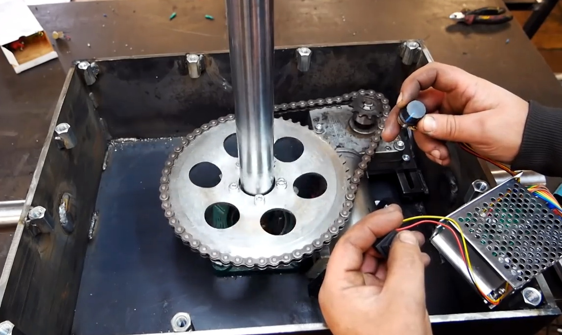
Step 2: physically mount motor to rotary table. On some tables, the shaft is supported on one end by a piece that bolts on. This provides convenient mounting. You may be able to machine a plate that has the original mounting holes, a bore for the bearing, and 4 holes for standoffs that match the stepper motor mounting holes. You will need a flex coupling. Bear in mind that the position of the shaft determines how well the gears mate and how much backlash there is. You may want slots for the mounting holes so you can slide the plate.
Step 5: PC interface. If your laptop has a parallel port, all you need to do is connect ground, step, and direction. The latter two can be connected to D0 and D1 on the parallel port. You will configure the software to tell it what pins you used. Parallel ports are going the way of dodo birds. USB->Parallel adapters are not suitable. USB is a bit trickier, though there are some stepper controllers available: here is one: http://www.usbcnc.com/index_products.html. I have seen a cheaper one designed by someone here or on CNCzone that looked halfway decent but can"t find it at the moment. About EU$69, USB, PIC based, 3 axis, no source code, windoze software included. Looked adequate for what you are doing but not for my purposes:

A popular question that we hear is, “How do I size a motor for my application?” This post looks at an example Rotary Index Table application and provides the equations and considerations needed to make the appropriate motor selection.
First, consider your machine’s movement. In our sample case of a Rotary Index Table, an engineer will need to first define all relevant information that will be used later in the Torque calculation. Typical information we will need includes:
Since we want to define the required motor torque, we want to be sure that we are using values that pertain directly to the motor itself. If there is a gearbox in the system, we need to be sure to reflect the required values back to the motor. We will need to determine the acceleration torque, deceleration torque, constant torque, and any torque due to gravity on the system. For this exercise, we will assume the index table is in a horizontal position, so the torque due to gravity will be zero.
Once we know the angular acceleration of the motor, we need to calculate the inertia of the load connected to the motor. In this case, we can approximate the index table inertia using the formula for a solid cylinder.
The load on the index table must also be taken into account. If the load is distributed evenly over the indexed surface, we can add this load into table weight to calculate the inertia of the complete system. If the load is not distributed evenly, then a separate load inertia will need to be determined, Jload.
Depending on the design of the system, there may be a constant friction torque, Mfriction, which must also be accounted for in the motor sizing. The amount of this constant torque will be dependent on the friction coefficient of the system and the weight of the table and load. Again, if there is a speed reduction in the system we can reflect this back to the motor shaft.


 8613371530291