
diy rotary table for milling machine free sample

Years ago, before I learned CNC, I owned a Phase II 8″ horizontal/vertical rotary table that I purchased from Kap Pullen’s Getmachinetools.com store. He has them at a good price, BTW, and he’s a darned nice fellow to deal with as well as being a frequent HSM contributor. Anyway, its a nice little table, but I hadn’t done a whole lot with it for quite a while after purchasing it. As is so often the case, one day, a project landed on my doorstep and I was glad to have it.
Before I could get started, however, I had to make some accessories for it. Basically, I needed some T-Nuts to fit the table, as well as a little fixture that makes it easy to hold a plate up off the table through a hole in the center so you can machine it. The latter, what I call a “plate machining fixture”, was inspired by something similar I saw the Widgitmaster of CNCZone fame using to make Dremel clamps for his mini-router:
I turned the round spigot using the 4-jaw on the lathe. I’m making the fixture out of MIC-6 aluminum plate, which is pre-ground very flat on the sides. This is a 5 inch by 3 inch piece. I’ve clamped it to the rotab using my T-nuts and the regular mill clamps and step blocks. It is sitting on parallels to make sure I don’t cut into the table. You can also see how I’ve clamped the rotary table to the mill table using a big cast iron V-block I have. You can never have to many blocks with precision faces hanging around!
Having a 4-jaw chuck on your rotary table is mighty handy! Because it’s a 4-jaw, you can dial in the workpiece by adjusting the jaws until it is perfectly concentric with the table’s axis of rotation. The best way is to make an adapter plate that attaches to the back of the chuck in the same way that your lathe does so you can exchange lathe tooling with the rotab. Here is an example:
For the example, the chuck is threaded onto the adaptor plate, and then the holes in the adapter plate’s flange are used to bolt down to T-nuts on the table.
In my case, I bought a 4-jaw from Shars brand new, and simply drilled some through-holes in the chuck to mount to the table directly without an adapter plate:
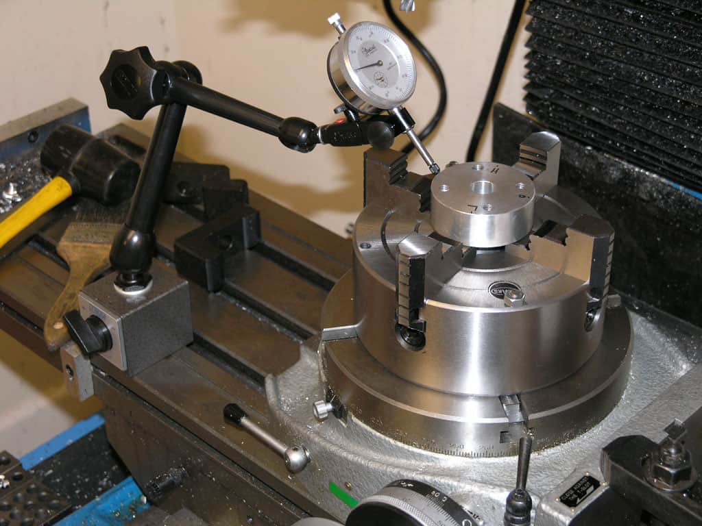
First, you want to make sure your part is properly centered on the table. To do that, I clamp the table down on the mill table (no special place is needed), put my Indicol indicator holder on the mill spindle, and find some round feature on the part to indicate on. For example, on the plate milling fixture above, indicate on the round boss, or on the center hole. Spin the table and bump the part in until spinning the table doesn’t move the indicator.
Second, locate the center of rotation directly under the mill spindle. You can simply use the X and Y table handwheels to do this. Use that Indicol to indicate off of a circular feature you want centered under the spindle. Turn the indicol around on the spindle and adjust the handwheels until the indicator stays put relative to the spindle position. A Blake Coaxial indicator will make this last even simpler.
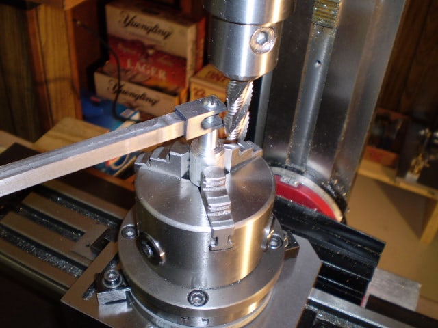
When you’re rounding partially by cranking a part around on the rotary table, it’s really easy to go a little too far and screw things up. The answer is to drill the end points to make the exact stopping point on the rotab a lot less sensitive:
Centering with a Blake indicator is really fast, but what if you don’t have a Blake, or worse, what if your mill is too small to accomodate one? Here is a nice solution I found on a German site. This fellow has made an ER collect fixture for his rotary table, and has taken care that when installed on the table, the axis of the collet is aligned with the table’s axis. He can then place a dowel or other straight pin in the collet and line up until it will go into a similarly sized collet on the spindle. Nice trick! It’s similar to how Widgitmaster showed me to align a drill chuck on a QCTP to the lathe centerline with a dowel pin held in the lathe chuck.

For a corner fillet weld such as those, it may help if you grind off half of each corner on the slotted plates giving a 45 deg V. This will help to ensure the weld gets good penetration and strength at the same time as allowing you to retain the original edges for alignment.

This website is using a security service to protect itself from online attacks. The action you just performed triggered the security solution. There are several actions that could trigger this block including submitting a certain word or phrase, a SQL command or malformed data.
I am wondering how it would work to mount a stepper motor or servo motor on the rotary table. What all would I need in order to make a laptop computer operate the rotary table?Sherline makes a very small rotary table that is just what I am looking for but it is tiny. I need something bigger and stronger. The sherline looks like you can program a certain number of divisions and then every time you hit the button it moves to the next location.
Well, depends on your skills. You need to be able to design and machine a simple mounting plate, connect up wires to printed circuit board screw terminals, run some software, etc. Your immediate application doesn"t require maximum performance. Steppers should be ok, and you won"t need more expensive motors, controllers, and lots of fine tuning. Just don"t try to push the speed limits unless you know what you are doing.
Step 1: measure the amount of force it takes to turn the wheel, so you know what size stepper you need. Put some load on the table, like a heavy vise and pull the edge of table with 50+lbs of force (1/4 horsepower, scale up as needed) to simulate machining forces (although in your immediate app, you probably won"t be machining and moving at the same time). Give yourself a safety factor. A double ended shaft is recommended, so you can mount a handwheel on back end for manual operation. For a small table like the sherline, most NEMA-23 motors should work. For a larger one, you may need higher torque NEMA-23, NEMA-34, or geared steppers.
Step 2: physically mount motor to rotary table. On some tables, the shaft is supported on one end by a piece that bolts on. This provides convenient mounting. You may be able to machine a plate that has the original mounting holes, a bore for the bearing, and 4 holes for standoffs that match the stepper motor mounting holes. You will need a flex coupling. Bear in mind that the position of the shaft determines how well the gears mate and how much backlash there is. You may want slots for the mounting holes so you can slide the plate.
Step 4: Power supply to match your motor driver. Most will let you use a voltage higher than the rated voltage of the motor. This gives much better performance. You can reduce the current rating of the power supply by roughly the ratio of the power supply voltage to the motor voltage. You may need up to twice as much because two windings may be energized at the same time. Power supplies can be had cheap on ebay. Wire to stepper motor driver board. Be careful NOT to ground the negative lead at the power supply (and don"t use a power supply that won"t let you float ground). Otherwise, the voltage drop accross the negative lead causes ground current loops which can be bad for your computer. Ground at the motor driver only.
Step 5: PC interface. If your laptop has a parallel port, all you need to do is connect ground, step, and direction. The latter two can be connected to D0 and D1 on the parallel port. You will configure the software to tell it what pins you used. Parallel ports are going the way of dodo birds. USB->Parallel adapters are not suitable. USB is a bit trickier, though there are some stepper controllers available: here is one: http://www.usbcnc.com/index_products.html. I have seen a cheaper one designed by someone here or on CNCzone that looked halfway decent but can"t find it at the moment. About EU$69, USB, PIC based, 3 axis, no source code, windoze software included. Looked adequate for what you are doing but not for my purposes:
Leave yourself some room to expand. Put a motor on your X axis, for example, and now the computer can cut your gear with a little programming and you have a power feed.
The mill rotary table is one of the main accessories of milling machine. As a precision work positioning device, it is widely used for indexing drilling, milling, circumferential cutting, boring, etc. The rotary turn table for milling machine is made from casting with high quality, can work with a set of dividing plate.
Both vertical and horizontal with two functions. Circle cutting, indexing drilling, milling and more complicated work are possible when the vertical position of the table is used together with the tail part.
Three dividing plate set(Plate "A" - 15, 16, 17, 18, 19, 20 Plate "B" - 21, 23, 27, 29, 31, 33 Plate "C" - 37, 39, 41, 43, 47, 49). A set of wrench and screws are free for you with your installation.
The vertical & horizontal rotary table is one of the main accessories of milling machine. As a precision work positioning device, it is widely used for indexing drilling, milling, circumferential cutting, boring and so on.
Our amazing rotary table is made from HT200 casting with high quality. It has already passed the ISO9001 quality system certification. They are are very popular on the market for their superior performance, excellent design and reasonable cost. They are definitely your best choice!
Our rotary table is both vertical and horizontal with two functions. When the vertical position of the table is used together with the tail part, it is also possible to complete circle cutting, indexing drilling, milling and more complicated work.
HT200 casting has good casting performance, shock absorption performance as well as high strength heat resistance. It ensures the of superior performance the machine and provides you a good sense of use.
It"s not difficult for you to adjust the rotary table milling machine. What you should to do is just adjust the handle to the position where you want. Because the precise scale is marked on the dial.
If you purchase our product, we are going to give you a free wrench, 2 positioning keys and screws. When you install the vertical & horizontal rotary table, these accessories will bring you a lot of conveniences.
This machine is designed for milling, drilling, fixture boring and many common workshop applications. It makes it possible for operators to drill or cut work at exact intervals around a fixed axis in the process of working.

Centroid OEM Machine Tool Manufactures offer a wide variety of Centroid CNC equipped machine tools.. click to to find a Centroid equipped CNC machine tools..
Small Milling Machine CNC Control system: $18,385M400 3 axis with 1Kw AC Brushless Yaskawa servo motors and drivesMedium Milling Machine CNC control system: $22,175M400 3 axis with 2Kw AC Brushless Yaskawa servo motors and drivesLarge Milling Machine CNC Control system: $25,760M400 3 axis with 4.4Kw AC Brushless Yaskawa servo motors and drives
Knee Mills, Bed Mills, Routers:M400S $13,709 IN STOCK! Ready to Ship, use order #StockSFlat Bed Lathes, Small Slant Bed Lathes: T400S $13,279,click for pdf quote
Auto part set, Auto tool set, 3D contouring, 4th and 5th axis machining, Available in OEM configurations, Professional Installation with Service & Training and DIY CNC kits for both new machines and retrofit upgrades.
From the May issue of Modern Machine Shop Magazine " A CNC retrofit provides improved reliability and functionality compared to an older machine’s original control, and this is helpful in a number of ways. For example, a more intuitive control interface can help speed setups and minimize the chance for programming and/or setup mistakes, which could possibly damage or scrap a high-value work piece. Similarly, shops are also more confident in quoting work for large, expensive parts knowing the new control won’t hiccup partway through an operation and cause the part to be damaged. Shops also are better-positioned to take in “hot” jobs that require fast turnaround due to the retrofitted machine’s improved"... click here to see the complete article in PDF.
CENTROID Boss series II retrofit customer testimonial"The quality and workmanship of the CENTROID equipment was outstanding and very professional. CENTROID was able to custom tailor the control to allow us to continue to use our rotary milling arrangement as before and even expanded our capability. The short story is that we ended up with a four axis CNC mill for less than half the cost of the three axis Haas. This includes the work that was done by our staff."

This website is using a security service to protect itself from online attacks. The action you just performed triggered the security solution. There are several actions that could trigger this block including submitting a certain word or phrase, a SQL command or malformed data.

New – Open box: An item in excellent, new condition with no functional defects. The item may be missing original packaging and may have been used for testing or demo purposes. The item includes accessories found with the original product and may include a warranty. See the seller"s listing for full details and description.See all condition definitionsopens in a new window or tab

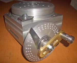
About 3 years ago I bought a cheap rotary table that I converted by taking off the handle and replacing with stepper motor. I used thrust bearings and whatever I could think of to minimize the backlash but it was a big FAIL. The internal worm gear mechanism was so sloppy that backlash was measured in degrees. Its been sitting on the shelf collecting dust. Since then I found out about Harmonic Drives and what high end CNC/Robotic systems use for rotational axis. A new harmonic drive is big $$$$ so eBay to the rescue. The gear head I used is planetary but made by Harmonic Drive Systems so it is very precise. It’s simple and just the right size for my small cnc. Since the stepper motor, gecko drive and gearhead was bought off eBay, it wasn’t that expensive. Under $150. I had upgraded my mini lathe to a bigger 5″ 3 jaw chuck. The 3″ chuck wasn’t being used anymore so I put it on the gearhead.


 8613371530291