
diy rotary table plans free sample
.jpg)
I attached the plans I made for CNC laser-cutting the sheet metal. This is a slightly improved version of what I have built in the video. It has bigger oval holes on the long reinforcement plates for easier accessing of the bolts for legs attachment.
The clamping holes on the top of the table are standard 16mm diameter holes. You could buy the expensive welding clamps or you could make your own for 5 bucks as I will show you later.

We have several routers and router tables in the Woodsmith shop. So it’s a bit of a stretch to say we “need” another router table. But this is a different deal. Honestly, it’s a mini router table. It’s mini because it uses a rotary tool instead of a full-size router. Like clamps, you can never have enough routing tools. If you don’t already have one, rotary tools and their matching router bits are readily available at your local home center. And they do a bang-up job when it comes to making things on a small scale. Despite their size, there’s little drop-off in getting precise results in most woodworking tasks. Building on these qualities was the driving force behind this project. It starts with a generously sized tabletop that has a no-maintenance plastic laminate top with a miter gauge slot to aid in the routing process. As for the maple fence, it’s got a T-track as well for featherboards and stop blocks.
This tailstock was designed for use with my rotary table. This has a centre height of 85 mm. I have made the height fully adjustable from 20 mm to 90 mm since it may be useful a...
.jpg)
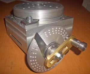
This is a re-post of how I built a home-brew rotary table for my mill just over two years ago. Having used it quite extensively, it still works perfectly well for my needs. During the posting, I"ll add some additional comments coloured red in the form of a review; it"s not often one gets to review or re-think a tool or operations after a period of time! I"ll also add a timeline to show how the build progressed.
Some research turned up bits and pieces of information on RTs, and then I hit gold on DeanW"s build of his rotary table - excellently detailed as always by Dean - and the plans available there. Thank you both Dean and Steve
I sourced and scrounged whatever materials I would need for the build; some I had lying around, and a lot I had to buy. I ended up with: Some bits of 10x60mm flat bar and a bit of 12mm plate for the base, a lump of cast iron for the table, phosphor bronze to make the gear out of, an old bit of bolt for some material to make diverse bits, aluminium for the handwheel, a brand new angular contact bearing, a bit of shaft from a printer with 2 small bearings to salvage for mounting the hand wheel shaft, and some 8mm and 16mm silver steel to make the shaft, worm and gear cutter from:
Then I clamped the plate to the mill table with some bits from the clamping kit and supported on two identical bearing outer rings as spacers, and milled three of the four sides square, with the two opposing sides I could get to, to the exact width for the plate (140mm):
Then I bored the hole bigger; (from 19mm to 61.97 mm) I started with a cheapy tungsten carbide tipped boring bar and 20 thou (~0.5mm) depths of cut and things went OK until I tried some bigger cuts. At 40 thou cuts things were going well, but then the carbide tip splintered and everything ground to a halt. Not feeling in the mood to try and re-sharpen the tool, and with the hole big enough for my favourite HSS left-hand(that should be right-hand!) turning tool bit to have adequate clearance, I just plonked that in and finished the cut. I intentionally left a 0.5mm thick ridge about 2mm wide at the back.That was to allow the bearing I have to be pre-loaded without the center of it actually rising up and touching the bottom of the table later on :
Then I flipped the plate in the chuck - just loosened two adjacent jaws of the chuck, flipped, and tightened down the same jaws, making sure the plate was flush on the chuck teeth with no swarf trapped. There was no need to perfectly re-center it - the last facing was just to get rid of the scale and to make sure the top face was completely parallel with the bottom. As the table will be riding on this surface, I tried to get a better finish - and succeeded:
I first faced off the one side of the welded base frame in the mill. I made a couple of quick clamping plates from more of the flat bar I used for the base - just saw off and drill an 11mm hole to allow some pivot clearance for a 10mm bolt , and sawed the heads off a couple of 10mm bolts to make shorter clamping studs than are in my clamping kit. The "new" clamping plates was needed as the clamping plates in my clamping kit is too thick for the slots I milled in the base. (Two years later, and these same ad-hoc clamping plates still hold down the RT in use!) T-nuts and the clamping nuts came straight from the clamping kit. I cleaned the mill table VERY thoroughly before clamping down the piece on a bit of paper to prevent it slipping:
Then I flipped it upside down to do the other side. Same process as above - clean and a new piece of paper. With the slots now higher above the table, I needed thicker spacers for the off-set ends for clamping... I settled on using some of the triangular step blocks from the clamping kit; a small one and larger one combined to provide the height. I couldn"t use the flat bar clamp plates as-is on just one triangle block, as it is both a bit soft and too rounded on the ends to ensure a good grip on the step block. I don"t recall ever seeing step blocks used in combination like this to , but it worked a treat
I removed the 4-jaw from the lathe with the table-in-making still mounted on it, and set it aside. The 3-jaw went on, and I started on the main shaft. First off, cut a bit off the big bolt from the first photo in this thread:
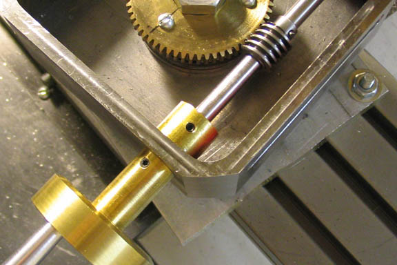
I flipped the main shaft-in-making in the 3-jaw, and turned the flange section that mounts into the back of the table. The outside of the flange actually becomes a register to keep the shaft concentric with the table, and was turned as accurate as I could for a light push fit into the hole in the table. For some reason I got a poor surface finish; but could not do anything about it. This photo shows the part with the right hand section turned down to "register" size and the end already faced:
I centered the chuck using the table feeds and a bit of that 16mm silver steel in the drill chuck to go into the hole, zeroed the X handwheel and dialled in the 17.5mm offset I needed. Drilled the first hole, loosened the clamp, rotated the chuck against the fixed blocks to maintain position, and indexed with the little square on the same "side" of the next jaw. Clamp down the chuck again, drill & repeat for next hole... QED
Next the holes needed countersinking from the back side... My countersink bit was too big, and waaay to short to reach in there. A broken 8mm drill bit volunteered, and I carefully ground its end to a 90 degree angle with suitable cutting faces. That made countersinking easy, and the holes turned out quite well with no chatter:
The last step, was to punch a witness mark into the flange and the back of the table; these I then "connected" with a scribed line - this will be used to make sure everything can be put back exactly the same at a later stage:
Then I used the punch to mark the table for the screw locations; simple; keep the alignment mark I made aligned; the punch is a close fit in the holes and stands upright by itself in each hole; and a good whack with a hammer on it and each center is marked:
I carefully centered and drilled each hole 4.2mm and 7mm deep on the mill with the chuck clamped to the table. After each hole, I used the drill chuck as a guide to run in the first tap from my M5 tap set. It only left a couple of threads on each hole before bottoming out, but enough to start the 2nd tap outside of the mill on the workbench. Each hole was run down with the second tap till it bottomed. Then the holes were run through with my modified version of an M5 plug tap - it had a pointed tip that I ground down while building "Fred" to really thread some holes to the bottom:
I mounted the 4 jaw with the table/shaft assembly back on the lathe. I know my 3-jaw grips eccentric by about 2 thou - but dead parallel from the chuck to about 100mm away from it - on a 26mm workpiece, and when I tested the shaft on the whole lot as mounted now with a dial indicator, that"s what I got. About 0.05mm eccentricity along the shaft"s entire length, but it was parallel. The outside of the table part as mounted was still spot-on center. So I carefully turned down the shaft part to the needed 25mm for the bearing inner race; it was at 26.5mm so for a first cut I just took off an infeed of 20 thou (that takes _just) over 1mm - off the total diameter). Then I measured the piece to be sure - it was down 25.48mm. I honed the cutting bit in-place on the lathe; just a couple of light touch with the oilstone - then went down to just over size at 25.1mm. A last cut part-way for the last 0.1mm, and I stopped for a test with the bearing and it lightly pressed over - so I finished the cut:
Next I turned the shaft down to 24mm up to a point 15mm away from the base of the table; the bearing is 17mm thick, and with the slight indentation in the table and the offset lip in the bearing mount hole in the base, that leaves me room for threading and run-out to the bottom of the bearing inner race. The 24mm section will be single-point threaded at 1mm pitch for the bearing pre-tensioner nut. I stopped short of the threading; that will take a while, and had better wait for the weekend.
Looking for something more to do, I decided on doing the holes to bolt the base top to the frame. I forgot to mark out the circle the table would run on on the base top plate, and being hit by a sudden sense of aesthetics, I needed to "see" a ring on the base top plate where the table would run. I pressed the bearing in the plate, and fit the whole lot over the shaft and used a permanent marker to mark the outline of the table on the plate:
First thing, I decided to make the pre-load nut. I removed the 4-jaw chuck (with table in making et al) from the lathe and put back the 3-jaw with outside jaws. Some 50mm aluminium rod was then turned down to just under 40mm for just long enough to make an 8mm wide nut and allow parting off. Then I drilled it out to 19mm for the same depth (19 mm, as it is my biggest drill):
Next I did some more work on the nut in the mill. I want to be able to lock that nut in position when fitting the table together, so it needed some method of achieving this. I slit and counterbored it on one side with a 6mm center cutting slot mill to clear the head of an M3 cap screw, then center drilled the bottom of the counter bore, and ran a 2.5mm drill (that"s for M3 tapping) right through, and then just drilled 3mm down to the slit for thread clearance. Then the 2.5mm section remaining below the slit was tapped M3 for as deep as my taps would go. I also milled two opposing flats on it for use when tightening it up. I didn"t take photos of every step mentioned here; but here are two I did take:
Then I sat down on the bar stool I keep handy (my "working table" is a bit high), and tapped each hole. The 5 mm clearance holes in the top plate are excellent tap guides to keep things square when starting with the first tap, so nothing fancy required as guide. Just manual work
The last challenge was mounting the vertical slide to the mill table. I nearly started cutting metal to make new T-nuts and so on, when I noticed the cross-slide extension I made for the lathe about 4 years ago. Some checking followed; and YES! - I can clamp it to the mill table to mount the vertical slide on. The completed assembly looks like the cobbled together solution that it is, but it should work:
The Bits "n Bobs mentioned is a block of brown stuff... My metals are too precious to waste on a once-off use like this, so wood it will be. With the 4-jaw still occupied by the table-in-making, the wood "jumped" onto the face plate after some persuasion. I then started boring out a pocket to fit a bearing in - after center drilling and drilling a 6mm hole right through the block:
A bit of a revelation to me as well; the ideas I had for making the worm shaft adjustable just went down the drain; not enough clearance, so it"s back to a bit of head scratching. And people wonder why I"m going bald...
When I got home after work, I had a good look at what I have already, and an eccentric will work a treat. The gear height is adjustable - so that"s not a problem; if it needs to move closer to the table top I can counter bore its face to clear the bearing pretension nut. Just some fine detail to finish off in my noggin - mostly related to the vernier scale I want on the assembly. As I"ll need to turn an eccentric soon, it"s time to get the table off the 4-jaw chuck. But this is no time to rush. I thought things through, and decided to graduate the table first; everything was set up ideally already; easy 72 divisions on the dividing head to mark 10 and 5 degree divisions on the table.
I haven"t made a spindle lock for my mill yet, so I opted to cut the division markings rather than broach them like Dean did. Darn; all my suitable toolbits have square shanks... So first, a tool was needed. Some 10mm silver steel, a 4mm cross-drilled hole through at a slight angle (not needed here, but possibly in future) and drill & tap the end for a 4mm grub screw. A short length off the 4mm round HSS sticks I keep around; a bit of grinding, and the result:
On to the mill - with the cutter set dead on center. I fed Y till the cutter tip just touched against the side of the table, and then moved the workpiece away on X. Another 0.2mm feed on Y and then I started cutting the first 10 degree graduation. Just deep enough in on X till it looked good to me, then I set the mill table stop to stop there. Then it was turn the DH, feed X to the stop & back out; repeat till all the 10 degree marks were done:
Bandsaws being the fairly rough machines that they are - and I"ve taken some pains to get mine as accurate as possible - the cut will inevitably shift slightly and not be perfectly square - especially in the vertical plane while cutting. I kept a careful look on the work, and when I detected too much of a deflection in cutting lines, I would stop the machine and turn the workpiece. I did this three times, as can be seen from the photo showing the table and the offcut:
Next it was back to the 4-jaw with the table. I put bits of soda can on the radius of the chuck jaws to prevent marring of the graduation marks. Then I dialed in the table dead on center on the outside body with just a vibration coming off the needle of my best indicator when revolving the chuck. This step is crucial in the long term:
I then added a close fitting 16mm "test bar" in the hole I bored initially through the table center. For me this is a length of silver steel that I know is straight; no fancy test equipment in my shop (YET!). I tested run-out on this a good distance away from the table body. This was to make sure that the back of the table is at a precise 90 degree angle to the axis so that I could turn the face completely parallel with the back side:
I then faced the table repeatedly with very light cuts - just 2.5 thou infeed at a time; I didn"t want a sudden heavy cut on the irregular bandsawed surface to knock things out of kilter! Then I bored the center hole out to 20mm diameter to a depth of 5mm - this will become the register for my lathe chuck mounting plate - and chamfered the register hole and internal 16mm step left at a 30 degree angle. This is for easy location of mounting the chuck plate in future, as well as for easy centering of the RT on the mill table with a bit of 16mm rod clamped in the collet chuck. As a final step, I used a sharp-pointed threading bit to turn light alignment rings on the face 10mm apart from each other.
This allow you to make accurate off-axis measurements of your speakers and keeps the pivot point on the font baffle which insures the mic distance remains the same. Using a rotary table allows the measurement mic to stay in a fixed location which minimizes the effects of the room if your making gated measurements. You can also change the design to make it higher if you want to use outdoors.

I guess I should explain how the dividing works. As you may have noticed there is no degree scale. Well you don"t need one and you don"t need trig tables. You will need a calculator.
This is a re-post of how I built a home-brew rotary table for my mill just over two years ago. Having used it quite extensively, it still works perfectly well for my needs. During the posting, I"ll add some additional comments coloured red in the form of a review; it"s not often one gets to review or re-think a tool or operations after a period of time! I"ll also add a timeline to show how the build progressed.
Some research turned up bits and pieces of information on RTs, and then I hit gold on DeanW"s build of his rotary table - excellently detailed as always by Dean - and the plans available there. Thank you both Dean and Steve
I sourced and scrounged whatever materials I would need for the build; some I had lying around, and a lot I had to buy. I ended up with: Some bits of 10x60mm flat bar and a bit of 12mm plate for the base, a lump of cast iron for the table, phosphor bronze to make the gear out of, an old bit of bolt for some material to make diverse bits, aluminium for the handwheel, a brand new angular contact bearing, a bit of shaft from a printer with 2 small bearings to salvage for mounting the hand wheel shaft, and some 8mm and 16mm silver steel to make the shaft, worm and gear cutter from:
Then I clamped the plate to the mill table with some bits from the clamping kit and supported on two identical bearing outer rings as spacers, and milled three of the four sides square, with the two opposing sides I could get to, to the exact width for the plate (140mm):
Then I bored the hole bigger; (from 19mm to 61.97 mm) I started with a cheapy tungsten carbide tipped boring bar and 20 thou (~0.5mm) depths of cut and things went OK until I tried some bigger cuts. At 40 thou cuts things were going well, but then the carbide tip splintered and everything ground to a halt. Not feeling in the mood to try and re-sharpen the tool, and with the hole big enough for my favourite HSS left-hand(that should be right-hand!) turning tool bit to have adequate clearance, I just plonked that in and finished the cut. I intentionally left a 0.5mm thick ridge about 2mm wide at the back.That was to allow the bearing I have to be pre-loaded without the center of it actually rising up and touching the bottom of the table later on :
Then I flipped the plate in the chuck - just loosened two adjacent jaws of the chuck, flipped, and tightened down the same jaws, making sure the plate was flush on the chuck teeth with no swarf trapped. There was no need to perfectly re-center it - the last facing was just to get rid of the scale and to make sure the top face was completely parallel with the bottom. As the table will be riding on this surface, I tried to get a better finish - and succeeded:
I first faced off the one side of the welded base frame in the mill. I made a couple of quick clamping plates from more of the flat bar I used for the base - just saw off and drill an 11mm hole to allow some pivot clearance for a 10mm bolt , and sawed the heads off a couple of 10mm bolts to make shorter clamping studs than are in my clamping kit. The "new" clamping plates was needed as the clamping plates in my clamping kit is too thick for the slots I milled in the base. (Two years later, and these same ad-hoc clamping plates still hold down the RT in use!) T-nuts and the clamping nuts came straight from the clamping kit. I cleaned the mill table VERY thoroughly before clamping down the piece on a bit of paper to prevent it slipping:
Then I flipped it upside down to do the other side. Same process as above - clean and a new piece of paper. With the slots now higher above the table, I needed thicker spacers for the off-set ends for clamping... I settled on using some of the triangular step blocks from the clamping kit; a small one and larger one combined to provide the height. I couldn"t use the flat bar clamp plates as-is on just one triangle block, as it is both a bit soft and too rounded on the ends to ensure a good grip on the step block. I don"t recall ever seeing step blocks used in combination like this to , but it worked a treat
I removed the 4-jaw from the lathe with the table-in-making still mounted on it, and set it aside. The 3-jaw went on, and I started on the main shaft. First off, cut a bit off the big bolt from the first photo in this thread:
I flipped the main shaft-in-making in the 3-jaw, and turned the flange section that mounts into the back of the table. The outside of the flange actually becomes a register to keep the shaft concentric with the table, and was turned as accurate as I could for a light push fit into the hole in the table. For some reason I got a poor surface finish; but could not do anything about it. This photo shows the part with the right hand section turned down to "register" size and the end already faced:
I centered the chuck using the table feeds and a bit of that 16mm silver steel in the drill chuck to go into the hole, zeroed the X handwheel and dialled in the 17.5mm offset I needed. Drilled the first hole, loosened the clamp, rotated the chuck against the fixed blocks to maintain position, and indexed with the little square on the same "side" of the next jaw. Clamp down the chuck again, drill & repeat for next hole... QED
Next the holes needed countersinking from the back side... My countersink bit was too big, and waaay to short to reach in there. A broken 8mm drill bit volunteered, and I carefully ground its end to a 90 degree angle with suitable cutting faces. That made countersinking easy, and the holes turned out quite well with no chatter:
The last step, was to punch a witness mark into the flange and the back of the table; these I then "connected" with a scribed line - this will be used to make sure everything can be put back exactly the same at a later stage:
Then I used the punch to mark the table for the screw locations; simple; keep the alignment mark I made aligned; the punch is a close fit in the holes and stands upright by itself in each hole; and a good whack with a hammer on it and each center is marked:
I carefully centered and drilled each hole 4.2mm and 7mm deep on the mill with the chuck clamped to the table. After each hole, I used the drill chuck as a guide to run in the first tap from my M5 tap set. It only left a couple of threads on each hole before bottoming out, but enough to start the 2nd tap outside of the mill on the workbench. Each hole was run down with the second tap till it bottomed. Then the holes were run through with my modified version of an M5 plug tap - it had a pointed tip that I ground down while building "Fred" to really thread some holes to the bottom:
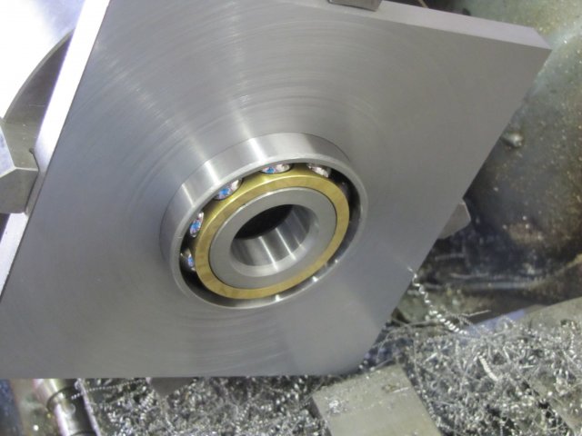
I mounted the 4 jaw with the table/shaft assembly back on the lathe. I know my 3-jaw grips eccentric by about 2 thou - but dead parallel from the chuck to about 100mm away from it - on a 26mm workpiece, and when I tested the shaft on the whole lot as mounted now with a dial indicator, that"s what I got. About 0.05mm eccentricity along the shaft"s entire length, but it was parallel. The outside of the table part as mounted was still spot-on center. So I carefully turned down the shaft part to the needed 25mm for the bearing inner race; it was at 26.5mm so for a first cut I just took off an infeed of 20 thou (that takes _just) over 1mm - off the total diameter). Then I measured the piece to be sure - it was down 25.48mm. I honed the cutting bit in-place on the lathe; just a couple of light touch with the oilstone - then went down to just over size at 25.1mm. A last cut part-way for the last 0.1mm, and I stopped for a test with the bearing and it lightly pressed over - so I finished the cut:
Next I turned the shaft down to 24mm up to a point 15mm away from the base of the table; the bearing is 17mm thick, and with the slight indentation in the table and the offset lip in the bearing mount hole in the base, that leaves me room for threading and run-out to the bottom of the bearing inner race. The 24mm section will be single-point threaded at 1mm pitch for the bearing pre-tensioner nut. I stopped short of the threading; that will take a while, and had better wait for the weekend.
Looking for something more to do, I decided on doing the holes to bolt the base top to the frame. I forgot to mark out the circle the table would run on on the base top plate, and being hit by a sudden sense of aesthetics, I needed to "see" a ring on the base top plate where the table would run. I pressed the bearing in the plate, and fit the whole lot over the shaft and used a permanent marker to mark the outline of the table on the plate:
First thing, I decided to make the pre-load nut. I removed the 4-jaw chuck (with table in making et al) from the lathe and put back the 3-jaw with outside jaws. Some 50mm aluminium rod was then turned down to just under 40mm for just long enough to make an 8mm wide nut and allow parting off. Then I drilled it out to 19mm for the same depth (19 mm, as it is my biggest drill):
Next I did some more work on the nut in the mill. I want to be able to lock that nut in position when fitting the table together, so it needed some method of achieving this. I slit and counterbored it on one side with a 6mm center cutting slot mill to clear the head of an M3 cap screw, then center drilled the bottom of the counter bore, and ran a 2.5mm drill (that"s for M3 tapping) right through, and then just drilled 3mm down to the slit for thread clearance. Then the 2.5mm section remaining below the slit was tapped M3 for as deep as my taps would go. I also milled two opposing flats on it for use when tightening it up. I didn"t take photos of every step mentioned here; but here are two I did take:
Then I sat down on the bar stool I keep handy (my "working table" is a bit high), and tapped each hole. The 5 mm clearance holes in the top plate are excellent tap guides to keep things square when starting with the first tap, so nothing fancy required as guide. Just manual work
The last challenge was mounting the vertical slide to the mill table. I nearly started cutting metal to make new T-nuts and so on, when I noticed the cross-slide extension I made for the lathe about 4 years ago. Some checking followed; and YES! - I can clamp it to the mill table to mount the vertical slide on. The completed assembly looks like the cobbled together solution that it is, but it should work:
The Bits "n Bobs mentioned is a block of brown stuff... My metals are too precious to waste on a once-off use like this, so wood it will be. With the 4-jaw still occupied by the table-in-making, the wood "jumped" onto the face plate after some persuasion. I then started boring out a pocket to fit a bearing in - after center drilling and drilling a 6mm hole right through the block:
A bit of a revelation to me as well; the ideas I had for making the worm shaft adjustable just went down the drain; not enough clearance, so it"s back to a bit of head scratching. And people wonder why I"m going bald...
When I got home after work, I had a good look at what I have already, and an eccentric will work a treat. The gear height is adjustable - so that"s not a problem; if it needs to move closer to the table top I can counter bore its face to clear the bearing pretension nut. Just some fine detail to finish off in my noggin - mostly related to the vernier scale I want on the assembly. As I"ll need to turn an eccentric soon, it"s time to get the table off the 4-jaw chuck. But this is no time to rush. I thought things through, and decided to graduate the table first; everything was set up ideally already; easy 72 divisions on the dividing head to mark 10 and 5 degree divisions on the table.
I haven"t made a spindle lock for my mill yet, so I opted to cut the division markings rather than broach them like Dean did. Darn; all my suitable toolbits have square shanks... So first, a tool was needed. Some 10mm silver steel, a 4mm cross-drilled hole through at a slight angle (not needed here, but possibly in future) and drill & tap the end for a 4mm grub screw. A short length off the 4mm round HSS sticks I keep around; a bit of grinding, and the result:
On to the mill - with the cutter set dead on center. I fed Y till the cutter tip just touched against the side of the table, and then moved the workpiece away on X. Another 0.2mm feed on Y and then I started cutting the first 10 degree graduation. Just deep enough in on X till it looked good to me, then I set the mill table stop to stop there. Then it was turn the DH, feed X to the stop & back out; repeat till all the 10 degree marks were done:
Bandsaws being the fairly rough machines that they are - and I"ve taken some pains to get mine as accurate as possible - the cut will inevitably shift slightly and not be perfectly square - especially in the vertical plane while cutting. I kept a careful look on the work, and when I detected too much of a deflection in cutting lines, I would stop the machine and turn the workpiece. I did this three times, as can be seen from the photo showing the table and the offcut:
Next it was back to the 4-jaw with the table. I put bits of soda can on the radius of the chuck jaws to prevent marring of the graduation marks. Then I dialed in the table dead on center on the outside body with just a vibration coming off the needle of my best indicator when revolving the chuck. This step is crucial in the long term:
I then added a close fitting 16mm "test bar" in the hole I bored initially through the table center. For me this is a length of silver steel that I know is straight; no fancy test equipment in my shop (YET!). I tested run-out on this a good distance away from the table body. This was to make sure that the back of the table is at a precise 90 degree angle to the axis so that I could turn the face completely parallel with the back side:
I then faced the table repeatedly with very light cuts - just 2.5 thou infeed at a time; I didn"t want a sudden heavy cut on the irregular bandsawed surface to knock things out of kilter! Then I bored the center hole out to 20mm diameter to a depth of 5mm - this will become the register for my lathe chuck mounting plate - and chamfered the register hole and internal 16mm step left at a 30 degree angle. This is for easy location of mounting the chuck plate in future, as well as for easy centering of the RT on the mill table with a bit of 16mm rod clamped in the collet chuck. As a final step, I used a sharp-pointed threading bit to turn light alignment rings on the face 10mm apart from each other.
Years ago, before I learned CNC, I owned a Phase II 8″ horizontal/vertical rotary table that I purchased from Kap Pullen’s Getmachinetools.com store. He has them at a good price, BTW, and he’s a darned nice fellow to deal with as well as being a frequent HSM contributor. Anyway, its a nice little table, but I hadn’t done a whole lot with it for quite a while after purchasing it. As is so often the case, one day, a project landed on my doorstep and I was glad to have it.
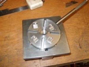
Before I could get started, however, I had to make some accessories for it. Basically, I needed some T-Nuts to fit the table, as well as a little fixture that makes it easy to hold a plate up off the table through a hole in the center so you can machine it. The latter, what I call a “plate machining fixture”, was inspired by something similar I saw the Widgitmaster of CNCZone fame using to make Dremel clamps for his mini-router:
I turned the round spigot using the 4-jaw on the lathe. I’m making the fixture out of MIC-6 aluminum plate, which is pre-ground very flat on the sides. This is a 5 inch by 3 inch piece. I’ve clamped it to the rotab using my T-nuts and the regular mill clamps and step blocks. It is sitting on parallels to make sure I don’t cut into the table. You can also see how I’ve clamped the rotary table to the mill table using a big cast iron V-block I have. You can never have to many blocks with precision faces hanging around!
Having a 4-jaw chuck on your rotary table is mighty handy! Because it’s a 4-jaw, you can dial in the workpiece by adjusting the jaws until it is perfectly concentric with the table’s axis of rotation. The best way is to make an adapter plate that attaches to the back of the chuck in the same way that your lathe does so you can exchange lathe tooling with the rotab. Here is an example:
For the example, the chuck is threaded onto the adaptor plate, and then the holes in the adapter plate’s flange are used to bolt down to T-nuts on the table.
In my case, I bought a 4-jaw from Shars brand new, and simply drilled some through-holes in the chuck to mount to the table directly without an adapter plate:
First, you want to make sure your part is properly centered on the table. To do that, I clamp the table down on the mill table (no special place is needed), put my Indicol indicator holder on the mill spindle, and find some round feature on the part to indicate on. For example, on the plate milling fixture above, indicate on the round boss, or on the center hole. Spin the table and bump the part in until spinning the table doesn’t move the indicator.
Second, locate the center of rotation directly under the mill spindle. You can simply use the X and Y table handwheels to do this. Use that Indicol to indicate off of a circular feature you want centered under the spindle. Turn the indicol around on the spindle and adjust the handwheels until the indicator stays put relative to the spindle position. A Blake Coaxial indicator will make this last even simpler.
When you’re rounding partially by cranking a part around on the rotary table, it’s really easy to go a little too far and screw things up. The answer is to drill the end points to make the exact stopping point on the rotab a lot less sensitive:
Centering with a Blake indicator is really fast, but what if you don’t have a Blake, or worse, what if your mill is too small to accomodate one? Here is a nice solution I found on a German site. This fellow has made an ER collect fixture for his rotary table, and has taken care that when installed on the table, the axis of the collet is aligned with the table’s axis. He can then place a dowel or other straight pin in the collet and line up until it will go into a similarly sized collet on the spindle. Nice trick! It’s similar to how Widgitmaster showed me to align a drill chuck on a QCTP to the lathe centerline with a dowel pin held in the lathe chuck.

So I’m going to do it again because this table is still a little bit sticky with some acrylic fumes, which are sitting on the surface. Now, if that stuff dries on.
The Leslie appears on classic tracks by Jimi Hendrix, David Gilmour, Stevie Ray Vaughan, Jeff Beck, George Harrison, and countless others who used the seductive sounds of spinning speakers to add a unique touch to their tracks. Check out “Cold Shot” by Stevie Ray Vaughan, “Max’s Tune” by the Jeff Beck Group, and “Any Colour You Like” (Wembley 1974) by Pink Floyd for some excellent examples of rotary-speaker guitar tones.
Leslie speakers operate on a principal called the Doppler effect. This is a physical phenomenon that describes the change in frequency as an object changes position relative to a sound source. As a sound source gets closer to you, it will increase in pitch and volume, and the opposite will happen as it moves further away. The Leslie speaker operates on this principal on a relatively small scale, making the effect more subtle then a moving ambulance siren, but all the more beautiful. I always wondered if the Doppler effect could be applied specifically to the guitar. What would happen if a rotating speaker device was designed from the ground up for our 6-string weapon of choice? Could it maintain and embellish the frequencies of our instrument while giving that beautiful, room-filling, three-dimensional effect? Other than the vintage Fender Vibratone and scant offerings from Hammond-Suzuki and Motion Sound—some guitarists might also recall the elusive Mesa Boogie Revolver—nothing really scratched my itch. So, ever a believer in the DIY spirit, I decided to build one.
Part 1: Assembling the CabinetStep 1.Start by measuring and cutting out the first three 24"x18" Baltic birch pieces—the cab’s front and sides—using a table saw or jigsaw. Make sure you follow the old woodworker’s creed: “Measure twice, cut once.”
Step 3. Now we need to cut matching windows into the front, sides, and removable rear panel. Use your table saw or jigsaw, and make sure to follow the measurements shown in Fig. 3.
Part 3: Building the Motor AssemblyStep 15. Now we cut a hole in the Styrofoam baffle (Fig. 15). If you are using a hot knife, be sure to work in a well-ventilated area. If you don’t have a hot knife, a good utility knife or hacksaw will work too. The width and depth of the hole will affect how the Doppler effect sounds in your rotary cabinet. To ensure burly shifting tones, I cut a medium-sized hole that was both deep and high.
Step 19. Now comes one of the most important steps in the entire assembly—making sure you properly mount the baffle. If the Styrofoam is not mounted exactly in the center, at higher speeds it will wobble all over the place and shake the entire cabinet. Take plenty of time and be very calculated in your approach. To find the center, use the “chord” method. There’s an excellent tutorial for this on YouTube called “How to Find the Center of a Circle” by Tomahawk DIY.
Step 21. Take your scrap wood and find its center. If you can, I recommend using a circular piece since that’ll help with rotary balance. If it’s a circle, find the midpoint on the piece of wood by repeating Step 19, and if it’s a square piece, find the midpoint by repeating Step 16.
Just like that, you have now finished your very own rotary speaker cabinet! Plug it into your favorite amp’s speaker output, and then plug in the IEC power cable. Turn on the unit, set the speed where you like it, and fire away!
If you’ve trudged through this wilderness of wood, wires, speakers, and Styrofoam, you’ve come to the final and most critical question: How does this DIY rotary speaker sound? I recorded two stereo clips, so I’ll let you be the judge of that.
These are the signal paths for both samples. The clean sample is a Strat loaded with David Allen Echoes pickups plugged into a Ceriatone OTS Mini 20, and an Origin Effects Cali76 Compact Deluxe compressor into the DIY cab. The dirty sample is the same Strat loaded with Echoes, the Ceriatone OTS Mini 20, and a Gurus Amps SexyDrive MkII into the DIY cab.


 8613371530291