
false rotary table supplier

Drilling involves pipe handling operations in a wellbore, and this in turn requires a false rotary table, a vital cog in the overall success of the operations. At ShalePumps, the need for constant improvement has resulted in an extensive range of precision engineered equipment, of which the false rotary table occupies the limelight.
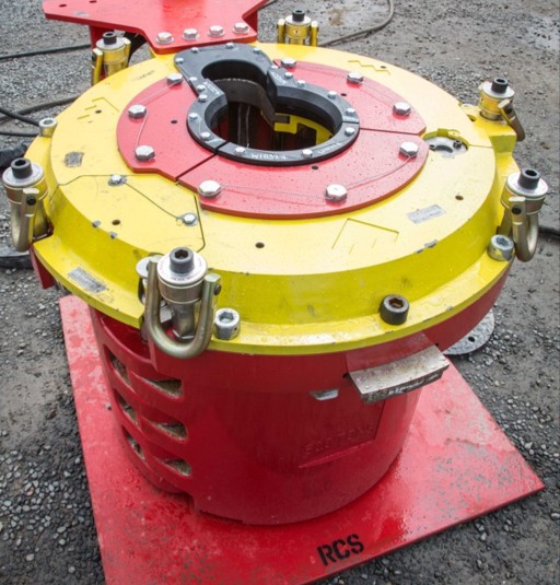
This hydraulically driven false rotary table is guaranteed to seamlessly engage the tubulars in the wellbore. Pivotal to drilling operations are the sequence of engaging and lowering tubulars into the wellbore. The false rotary table manufactured at our facility is a fine example of harmony between design, materials and precision engineering.
Featuring a mighty load capacity of 1.3 million pounds operating at a maximum speed of 20 rpm, the false rotary table assists the drilling operations in continuous long drawn operations. Pipe handling requires the seamless and sturdy operation of the false rotary table.
ShalePumps, backed by substantive body of experience and knowhow has developed this high performance false rotary table to ably support drilling operations by incorporating a blend of advanced materials and precision engineering. With a guaranteed long life and trouble free run, the ShalePumps false rotary table spins other models out of reckoning.

A drilling rig is not complete without the rotary table, a mechanical device that provides a clockwise rotational force to a drill string and enable the drilling of a borehole. The rotary speed is identified as rpm (rounds per minute) the amount of times the device can complete a full revolution per minute. When the drilling process covers the pipe handling operation in the wellbore, it will require a false rotary table for higher chances of success. Shale Pumps provides this device as a hydraulically driven equipment to seamlessly engage tubulars in a wellbore. We manufacture false rotary tables in-house to ensure precision engineering and the highest-quality design and materials.
When it comes to pipe handling, it is crucial for equipment to be seamless and sturdy to be reliable. Shale Pumps’ false rotary table can handle up to 1.3 million pounds of load while maintaining constant operation at a 20 rpm on maximum speed, making it ideal for long drawn and continuous operations. We developed our false rotary tables, like the SP-FRT375 to perform in the most demanding drilling jobs, and we achieve this only with precision engineering and by using advanced materials.
The false rotary table at Shale Pumps is backed by a guarantee for longevity and trouble-free performance. This way, it outperforms false rotary tables offered by other manufacturers. Our device helps you save money and boost productivity in the long run with lower maintenance costs. Every rotary table equipment has been tested in compliance with the latest industry regulations for safety, efficiency, and quality.
When choosing a false rotary table, be sure that it is being sold by a reputable manufacturer and supplier, like Shale Pumps. That way, you can be sure that the equipment has been manufactured and assembled following a strict and proven format, which ensures its quality. Shale Pumps corrects any material defects and problems with assembly immediately and take note of them to prevent them from occurring again.
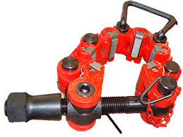
Diversified offers a wide range of Manual Elevators such as Side Door Elevators, Single Joint Elevators, Slip Type Elevators, Safety Clamps and Rotary Slips for 2-3/8” diameter tubing to 30” diameter casing.
Rotary Slips:Our inventory of Rotary Slips includes SDS, SDML, SDXL and CMS-XL variants from 2-3/8” to 30” OD. We can also provide Low Penetrating Dies for Chrome running and handling applications upon request.
[0004] Drilling is accomplished by utilizing a drill bit that is mounted on the end of a drill support member, commonly known as a drill string. To drill within the weilbore to a predetermined depth, the drill string is often rotated by a top drive or rotary table on the drilling rig. After drilling to a predetermined depth, the drill string and drill bit are removed and a section or string of casing is lowered into the weilbore.
[0009] The elevator is used to impart torque to the tubular section being threaded onto the tubular section suspended within the weitbore by the spider. To this end, a traveling block suspended by wires from a draw works is connected to the drilling rig. A top drive with the elevator connected thereto by elevator links or bails is suspended from the traveling block. The top drive functions as the means for lowering the tubular string into the wellbore, as the top drive is disposed on rails so that it is moveable longitudinally upward and downward from the drilling rig along the rotational axis of well center. The top drive includes a motor portion used to rotate the tubular sections relative to one another which remains rotationally stationary on the top drive rails, while a swivel connection between the motor portion and the lower body portion of the top drive allows the tubular section gripped by the elevator to rotate. The rails help the top drive impart torque to the rotating tubular section by keeping the top drive lower body portion rotationally fixed relative to the swivel connection. Located within the rig floor is a rotary table into or onto which the spider is typically placed.
[0013] Sometimes a false rotary table is mounted above a rig floor to facilitate wellbore operations. The false rotary table is an elevated rig floor having a hole therethrough in line with well center. The false rotary table allows the rig personnel to access tubular strings disposed between the false rotary table and the rig floor during various operations. Without the false rotary table, access to the portion of the tubular string below the gripping point could only be gained by ng hands venturing below the rig floor, which is dangerous and time-consuming. Manual labor is currently used to install and remove the false rotary table during various stages of the operation.
[0022] In yet another aspect, embodiments of the present invention include a method of forming and towering a tubular string into a wellbore using a remotely operated elevator system, comprising providing elevator links attached to a first elevator and a sliding false rotary table located above a rig floor, wherein the false rotary table is disposed in a landing position to axially support a tubular; axially engaging the tubular with the first elevator; locating the First elevator substantially coaxial with the weilbore on the false rotary table; remotely detaching the elevator links from the first elevator; and remotely attaching the elevator links to a second elevator. Embodiments of the present invention also provide a false rotary table disposed above a rig floor for use in handling tubulars, comprising a table slidable over a weilbore; and a hole disposed in the table, wherein the table is slidable by remote activation from a first, pipe-supporting position to a second, pipe-passing position and, in the pipe-supporting position, the hole is located over the wellbore.
[0023] Embodiments of the present invention also provide a false rotary table disposed above a rig floor for use in handling tubulars, comprising a base plate having a hole therein disposed above a weilbore; and at least two sliding plates slidably connected to the base plate, wherein the at least two sliding plates are remotely and independently slidable over the base plate to alternately expose the hole or narrow a diameter of the hole. In an additional aspect, embodiments of the present invention provide an apparatus for grabbing an oil-field mechanism, comprising links operatively connected to an oil rig and capable of grabbing the mechanism; and at least one spreading member operatively connected to each link and disposed between the links, the spreading member comprising a motive member, wherein the spreading member is remotely operable.
[00271 Figure 2 is a perspective view of the automated false rotary table of Figure 1 in position to land a tubular on the rotary table for the threading of additional tubulars thereon.
[0028] Figure 3 shows the automated false rotary table of Figure 2 with a first tubular section landed on the false rotary table with a first elevator.
[0033] Figure 8 shows the second tubular section lowered through the automated false rotary table and the automated false rotary table moved back to the position for landing tubulars shown in Figure 2.
[0035] Figure 10 shows the automated false rotary table of Figure 9 with the second elevator and the second tubular section landed on the automated false rotary table. Elevator links are shown detached from the second elevator.
(00441 Figure 21 shows the automated false rotary table of Figure 20 in position to land a tubular on the automated false rotary table for the threading of additional tubulars thereon.
(00451 Figure 21 A is a section view of a portion of a first elevator and a portion of the automated false rotary table of Figure 21 on which the first elevator is disposed.
[0046] Figure 22 shows the automated false rotary table of Figure 20 in the position to land a tubular, as shown in Figure 21. A second elevator having a first tubular section therein is landed on the automated false rotary table.
(00481 Figure 24 shows the automated false rotary table of Figure 20 with elevator links in position to lift the first elevator from the automated false rotary table.
[0049] Figure 25 shows the automated false rotary table of Figure 20, with the first elevator lifting a first tubular string formed by a second tubular section connected to the first tubular section. The second elevator is in the open position.
(0050] Figure 26 shows the automated false rotary table moved to the tubular-running position shown in Figure 20. The second elevator is moved to a position away from a hole in the automated false rotary table into which tubutars are run.
(0051J Figure 27 shows the automated false rotary table of Figure 20 in the tubular-running position of Figure 26. The tubular string is lowered through the hole.
[0052] Figure 28 shows the automated false rotary table of Figure 20 moved to the tubular-landing position shown in Figure 21. The first elevator having a tubular therein is in position to land on the automated false rotary table.
(0054] Figure 29 shows the automated false rotary table of Figure 20 in the tubular-landing position, with the first elevator landed on the automated false rotary
[0056] Figure 30 shows the first elevator on the automated false rotary table of Figure 20 having the elevator link retainer assemblies in the open position. The elevator links are in position to move the elevator link retainer assemblies on the first elevator to the closed position to retain the elevator links therein.
[0057] Figure 31 shows the first and elevators on the automated false rotary table of Figure 20, with the elevator links in the process of moving the elevator link retainer assemblies of the second elevator into the closed, retaining position.
(0058] Figure 32 shows the second elevator on the automated false rotary table of Figure 20 being lifted from the automated false rotary table to lock the elevator link retainer assemblies into the locked, closed, link-retaining position.
(0064] When referred to herein, the terms "links" and "elevator links" also refer to bails, cables, or other mechanical devices which serve to connect a top drive to an elevator. The term "elevator," as used herein, may include any apparatus suitable for axially and longitudinally as well as rotationally engaging and supporting tubular sections in the manner described herein. The term "tubular section" may include any tubular body including but not limited to a pipe section, drill pipe section, and/or casing section. As used herein, a tubular string comprises multiple tubular sections connected, preferably threadedly connected, to one another. Directions stated below when describing the present invention such as left, right, up, and down are not limiting, but merely indicate movement of objects relative to one another.
(0065] Figure 1 shows a first embodiment of an automated false rotary table 10 in the position for running one or more tubulars (see Figures 3-12) into a weilbore (not shown) below the false rotary table 10. A drilling rig (not shown) is located above the wellbore. The drilling rig has a rig floor (not shown), above which the false rotary
[0066] The automated false rotary table 10 includes a sliding table 15 which is moveably disposed on a track 20. The sliding table 15 is slidable horizontally parallel to the track 20. Most preferably, although not limiting the scope of the present invention, the sliding table 15 is capable of supporting approximately 750 tons of weight thereon.
[0067] The sliding table 15 has a hole 19 therein. The hole 19 in the sliding table is shown with three portions, including a narrowed portion 16 having a smaller diameter, a widened portion 17 having a larger diameter relative to the narrowed portion 16, and a control line portion 18. The narrowed portion 16 is utilized to support the weight of one or more tubular sections when an elevator axially and rotationally engaging the one or more tubular sections is landed on the false rotary table 10 (described below). The widened portion 17, which in one preferable embodiment has a width of at least 36 inches, allows the one or moretubular sections to pass through the rotary table 10 after the elevator releases the one or more tubular sections (described below). In Figure 1, the false rotary is in the position to allow the one or more tubulars to pass through the widened portion 17.
The tubular shape of the support 25 defines a hole beneath the sliding table 15 for passing tubulars through when desired. At any one time, the tubular-shaped support 25 remains substantially co-axial with the weilbore. Disposed on the outer diameter of the tubular-shaped support 25, at the same end of the sliding table 15 as the control line portion 18 of the hole 19, is at least one control line passage, here shown as two control line passages 26A and 26B. The control line portion 18 of the hole 19, in conjunction with control line passages 26A and 2GB, which in a preferred embodiment are each two inches by five inches, permit control lines 27A and 278 to travel through the automated false rotary table 10 without damage due to crushing the control lines 27A and 27B while passing through the elevator (described below).
The control lines 27A and 276 may be dispensed from a spool (not shown) located at, above, or below the rig floor while running the tubular to and/or through the hole 19 in the sliding table 15. The control lines 27A and 278, which may also include cables or umbilicals, may be utilized to operate downhole tools (not shown) or, in the alternative, to send signals from downhole to the surface for measuring welibore or formation conditions, e.g. using fiber optic sensors (not shown). Any number of control lines 27A-B may be employed with the present invention having any number of corresponding control line passages 26A-B. The control line portion 18 of the hole 19 in the sliding table 15 may be of any shape capable of accommodating the number of control lines 27A-B employed. As shown in Figures 1-12, the control line portion 18 includes a forked area with two separate hole areas, but it is contemplated that the present invention may fork into any number of separate hole areas to allow protected, unimpeded passage of any number of control lines 27A-B.
[O069 Brackets 30A and 306 are connected to the track 20 on opposing sides of the sliding table 15. The brackets 30A and 306 are not connected to the sliding table 15, and thus the sliding table 15 is moveable with respect to the brackets 30A and 30B and the track 20 (described below). The brackets 30A and 30B are shown connected to the track 20 by one or more pins 32A, 32B inserted through holes 31 A and 31 B in the brackets 30A and 308 and through holes (not shown), 218 disposed in the track 20. The brackets 30A and 306 may be connected to the track 20 by any other method or apparatus known to those skilled in the art.
[0070] Each bracket 30A, 308 is connected at one end to one or more hydraulic lines (not shown) which introduce pressurized fluid thereto. At the opposite end of each bracket 30A, 30B from the hydraulic line is an elevator retainer assembly 35A, 35B. The elevator retainer assembly 35A, 35B functions to retain an elevator in position on the false rotary table 10 at various stages in the operation. As shown, each elevator retainer assembly 35A, 35B includes a piston 36A, 36B disposed within a cylinder 37A, 378, and the pistons 36A and 36B are moveable inward toward one another in response to remote actuation due to fluid pressure supplied from the hydraulic line. Alternatively, the elevator retainer assembly 35A, 25B may include a piston/cylinder assembly actuated by a biasing spring, or the elevator retainer assembly 35A, 35B may extend to engage the elevator due to electronic actuation. The elevator retainer assembly 35A, 358 may include any other mechanism suitable for retaining an elevator which may be remotely actuated.
[00711 Figure 2 shows the false rotary table 10 in the position for landing one or more tubular sections on the sliding table 15. A piston and cylinder assembly (not shown) may be utilized to remotely actuate the sliding motion of the sliding table 15 over the track 20 to the position to land tubulars on the narrowed portion 16 of the hole 19 in the sliding table 15. The piston and cylinder assembly includes a piston moveable from a cylinder in response to the introduction of pressurized fluid (hydraulic or pneumatic) behind the piston to move the sliding table 15.
Alternatively, the sliding table 15 may be remotely moved by electric means or mechanical means such as a biasing spring. Figure 2 illustrates that the track 20, the connected brackets 30A and 30B, and the tubular-shaped support 25 remain stationary relative to one another and the rig floor while the sliding table 15 moves in the direction shown by the arrows.
[00721 Figure 3 shows the automated false rotary table 10 in the position for landing one or more tubulars shown in Figure 2. A first elevator 100 is shown landed on the narrowed portion 16 (see Figure 2) of the hole 19 in the sliding table 15. The first elevator 100 is preferably a door-type elevator having a supporting portion 110 pivotably connected to a door portion 120. As shown, each side of the door portion 120 adjacent to each side of the supporting portion 110 is connected by pins 111 B and (other side not shown) through holes 11 2B and (other side not shown) to holes 11 3B and (other side not shown) extending through the supporting portion 110 above and below the door portion 120.
(0073) The door portion 120 includes a first jaw 11 5A and a second jaw 11 5B, as shown in Figure 5. The first and second jaws 11 5A and 11 5B are pivotable outwards in opposite directions from one another to the position shown in Figure 5.
The first jaw 11 5A is pivotabie around the first pin (not shown), while the second jaw 11 5B is pivotable around the second pin 111 B to open the "door" to the first elevator to insert a tubular in the exposed bore of the first elevator 100, as shown in Figure 5, or to close the "door" to the first elevator 100 to retain a tubular, as shown in Figure 3.
[0081] In operation, the automated false rotary table 10 is initially disposed in the position for landing tubulars shown in Figure 2 before the tubular running operation commences. The piston/cylinder assembly (not shown) pivotably connecting the top drive and the elevator links 160 may be activated to pivot the elevator links 160 radially outward relative to the top drive to allow the first elevator 100 to pick up the first tubular section 150 from a location away from well center (typically tubular sections are picked up from a rack). The door portion 120 of the first elevator 100 is in the open position (see Figure 5) initially until the first tubular section 150 is placed within the first elevator 100 so that the first elevator 100 is below the female threads of the first tubular section 150. The jaws 11 5A and 11 5B of the door portion 120 are then are then moved to the closed position remotely, e.g., by introducing pressurized fluid behind a piston within a cylinder to pivot jaws 1 15A and 1 15B inward towards one another. Alternatively, the jaws 11 5A and 11 5B may be opened and closed by a biasing spring mechanism or electrical means. The tubular section is axially and rotationally engaged by the first elevator 100 upon closing the jaws 11 5A and 11 5B, as the female threads 155, which are seated in the corresponding inner surface 105 of the first elevator 100, define an upset portion of the tubular section 150 which cannot pass through the narrower hole within the first elevator 100 which exists below the inner surface 105 corresponding to an outer surface of the shoulder (the female threads 155). Deactivation of the piston/cylinder assembly connecting the top drive and the elevator links 160 pivots the elevator links 160, along with the connected first elevator 100 and engaged first tubular section 150, into substantial co-axial alignment with the top drive and the narrowed portion 16 of the hole 19 in the sliding table 15.
[00821 The top drive is then lowered by movement along its rails so that the first elevator 100 is lowered into contact with the sliding table 15, as shown in Figure 3.
While the elevator 100 is being lowered, prior to contacting the first elevator 100 with the sliding table 15, the elevator link retainers 165 are disposed around the lifting ears 1256, (not shown) of the first elevator 100, and the first elevator link retainer assemblies 1 30B, (not shown) are pivoted to hold the elevator link retainers 165 into position on the lifting ears 1 25B, (not shown). Figure 3 shows the next step in the operation. Upon contact of the first elevator 100 with the sliding table 151 the link retainer assemblies 130B, (not shown) pivot and release the elevator link retainers so that they are free to move outward from the lifting ears 1256, (not shown) of the first elevator 100. Figure 3 shows the elevator link retainers 165 released from engagement with the lifting ears 1 25B, (not shown).
[0083) The link spreader 170 is then activated to extend the first elevator links outward relative to one another. When using a piston/cylinder assembly as the link spreader 170, fluid pressure behind the piston extends the piston from the cylinder, thereby spreading the elevator links 160. The extension of the elevator links 160 from one another to an appropriate distance allows the elevator links 160 to clear the lifting ears 1 25B, (not shown) when the top drive is moved upward along its rails. Figure 4 shows the first elevator 100 located on the sliding table 15 with the first tubular section 150 engaged therein and the elevator links 160 removed from the first elevator 100.
[00871 Because the second elevator 200 is now engaging the entire tubular string 350, the first elevator 100 may be released from its engagement with the first tubular string 150 without dropping the first tubular string 150 into the hole 19 through the sliding table 15 and into the weilbore (not shown) below. To begin the lowering operation of the tubular string 350 into the weilbore, the second elevator 200 is moved upward longitudinally by the top drive moving upward along its track. This upward movement of the tubular string 350 initially disengages the first elevator 100 from the upset portion of the tubular string 350, or the female threads 155 of the first tubular section 150.
[0089] Next, the sliding table 15 is slidingly moved along its track 20 to the right into the position for running tubulars through the false rotary table 10, as shown and described in relation to Figure 1. The sliding table 15 is moved so that the first elevator 100 and the narrowed portion 16 of the hole 19 in the sliding table 15 do not interfere with the tubular string 350 and its female threads 155 being lowered below the sliding table 15. The sliding table 15 is slid by remote actuation. One type of remote actuation which may be utilized includes a piston/cylinder assembly (not shown), where the piston is moveable from the cylinder to extend the sliding table 15 in one direction upon introduction of pressurized fluid behind the piston within the cylinder or by a biasing spring. Other types of remote actuation are contemplated for use in sliding the sliding table 15 which are known by those skilled in the art.
(0090) The brackets 30A and 308 and the range of sliding motion of the sliding table 15 on the track 20 are preferably configured so that sliding the sliding table 15 to the right as far as possible positions holes (not shown) in the first elevator 100 which correspond with the pistons 36A and 366 (see Figure 6) adjacent to the pistons 36A and 36B of the brackets 30A and 308. When sliding the sliding table 15 to the right at this stage of the operation, the first elevator 100 in its open position remains in its place on the sliding table 15 and slides with the sliding table 15. The control lines 27A and 276, the tubular string 350, the tubular-shaped support 25 beneath the sliding table 15, the track 20, and the brackets 30A and 3GB attached to the track remain stationary relative to the sliding table 15 and the first elevator 100.
[0091) As shown in Figure 6, upon sliding the sliding table 15 to the right, the control lines 27A and 278 change from their location within the widened portion 17 of the hole 19 in the sliding table 15 into within the control line portion 18 of the hole 19. The tubular string 350 changes from its location within the narrowed portion 16 to within the widened portion 17. The first elevator 100 moves to a location between the brackets 30A and 30B.
[0092] After sliding the sliding table 15 to the right, the first elevator is retained in position by remotely activating the elevator retaining assemblies 35A, 356. When using pistons 36A, 36B and cylinders 37A, 378 as the elevator retaining assemblies 35A, 35B, pressurized fluid is introduced behind the pistons 36A and 365 within the cylinders 37A and 37B to force the pistons 36A and 36B inward towards the first elevator 100 and into corresponding retaining pin holes (not shown) in the outer surface of the first elevator 100. Figure 7 illustrates the elevator retaining assemblies 35A and 358 disposed within the retaining pin holes (not shown) to lock the first elevator 100 and prevent it from sliding movement.
[0093] The top drive is then moved downward along its rails so that the tubular string 350 is lowered through the widened portion 17 of the hole 19 in the sliding table 15 and through the support 25. The control lines 27A and 27B may be simultaneously lowered with the tubular string 350 through the control line portion 18 of the hole 19 and the control line passages 26A and 26B (shown in Figure 1). After the female threads 155 of the tubular string 350 are lowered through the widened portion 17, the first tubular section 150 running portion of the operation is finished; therefore, the sliding table 15 is remotely actuated as described above to slide the sliding table 15 back into the landing position shown in Figure 2 to allow an additional tubular section (not shown) to be added to the tubular string 350. When the sliding table 15 is moved back to the landing position, the first elevator 100 remains in the parked position due to the elevator retainer assemblies 35A and 358 retaining the first elevator 100 in a stationary position on the track 20. The sliding table 15 slides under the first elevator 100 to the position shown in Figure 8. The tubular string 350, control lines 27A and 27B, and support 25 again remain stationary while the sliding table 15 moves to the left along the track 20. The control lines 27A and 276 return to their location within the widened portion 17, while the tubular string 350 returns to its location within the narrowed portion 16 so that the sliding table 15 may support the weight of the tubular string 350.
[0094] After slidingly moving the sliding table 15 back to the tubular landing position, the tubular string 350 is lowered through the narrowed portion 16 until the second elevator 200 lands on the sliding table 15. The second elevator 200 operates in substantially the same manner as described above in relation to the first elevator 100 in Figure 3, so that the link retainer latches 2306, (not shown) of the second elevator 200 are pivoted from engagement with the elevator link retainers 165, permitting movement of the elevator links 160 outward from the lifting ears 2258, (not shown) of the second elevator 200. Figure 9 shows the second elevator landed on the narrowed portion 16 of the sliding table 15 and the elevator links rendered free to move outward from the lifting ears 225B, (not shown).
[0096) At this point in the operation, the second elevator 200 supports the weight of the tubular string 350 by preventing the female threads 255 of the second tubular section 250 from lowering through the bore of the second elevator 200 and through the sliding table 15. The elevator links 160 are pivoted outward, as described above, by the piston/cylinder assembly pivotably connecting the top drive to the elevator links 160. While the link spreader 170 still spreads the elevator links 160 outward from one another, the elevator link retainers 165 are placed adjacent to the lifting ears 1256, (not shown) of the first elevator 100 to straddle the first elevator 100. Figure 11 shows the link spreader 170 extending the elevator links 160 and the elevator link retainers 165 disposed adjacent to the lifting ears 1258, (not shown).
The upper end of the link retainer latch 186 has a cut-out portion 187, into which a protruding portion 188 of the elevator lifting ear 1 25B is placed. Link retainer arms are rigidly mounted to outer opposing surfaces of the link retainer latch 186, substantially perpendicular to the ink retainer latch 186 to form an "1.-shape". The link retainer latch 186 and the link retainer arms 180 are pivotable with respect to the lifting ear 125B, around the protruding portion 188. A torsion sprIng 181 extends through the link retainer latch 186 and the protruding portion 188 of the lifting ear 1258 to bias the link retainer latch 186 upward when the elevator link retainer assembly 1 30B is in the "open" position (see Figure 16).
[001011 Referring especially to Figure 16, elevator extensions 190 protrude outward from a lower portion of the elevator 100 substantially in line with and below the lifting ear 1258. The elevator extensions 190 and the lifting ear 1258, along with an outer surface of the elevator 100, form a cavity 191 for housing the lower portion of the elevator link retainers 165 (see Figure 13). The elevator extensions 190 each have curved outer surfaces 192 shaped to receive the curved outer surfaces of the arms of the link retainer latch 186. Disposed between the elevator extensions is a link retainer lock 183. The link retainer lock 183 is shaped has a hook portion which defines a cavity 193 shaped to essentially conform around the pin 182. The link retainer lock 183 is pivotable around the elevator extensions 190. A torsion spring 184 extends through holes in the elevator extensions and the link retainer lock 183 to bias the link retainer lock 183 upward when the elevator link retainer assembly 1 30B is in the "closed" position. A pin 185 extends downward from the link retainer lock 183, and is moveable upward and downward with respect to the elevator 100.
(001031 When the elevator 100 is lowered so that the base plate 131 of the elevator 100 lands on the automated false rotary table 10, the pin 185 is forced upward into the elevator 100. The upward motion of the pin 185 pushes the back end (not shown) of the link retainer lock 183 upward, thus counteracting the bias of the torsion spring 184 to pivot the hook portion of the link retainer lock 183 downward around the elevator extensions 190. Rotating the hook portion of the link retainer lock 183 downward unhooks the link retainer lock 183 from the pin 182, as shown in Figures 13 and 14. Figure 13 shows the elevator link retainer 165 within the elevator link retainer assembly 1 30B. The elevator link retainer 165 is extracted from Figure 14 for ease of viewing in describing the elements of the elevator link retainer assembly 1308.
(00105] To close the link retainer assembly 130B, the elevator links 160 are placed over the elevator 100 to straddle the elevator 100, with the elevator link retainers 165 adJacent to the elevator lifting ears 125B, (not shown). Referring to Figure 16 (which does not show the elevator link retainers 165 for ease of viewing), the elevator link retainers 165 are forced inward relative to one another when the link spreader 170 is retracted. The elevator link retainers 165 counteract the bias of the torsion spring 181 when the elevator link retainers 165 push against the link retainer arms 180. The link retainer arms 180 are forced inward within the cavity 191, and the attached link retainer latch 186 pivots downward relative to the lifting ear 125B around the elevator link retainer 165, as shown In Figure 13. The elevator is then lifted by the elevator links 160, which are engaged with the elevator 100 by the elevator link retainers 165 being looped around the lifting ears 1 25B, (not shown). The upward movement of the base plate 131 of the elevator 100 relative to the false rotary table 10 allows the pin 185 to again extend to its most extended position from the base plate 131, allowing the torsion spring 184 to again bias the hook portion of the link retainer lock 183 upward into engagement with the pin 182, so that the elevator link retainer assembly 130B, (not shown) is again in the closed position.
[00107] Figure 17 shows an alternate configuration of the first embodiment of the present invention. This embodiment is configured and operates in substantially the same manner as described above in relation to Figures 1-16, except for the hole 19 in the automated false rotary table 10 and the brackets 30A and 30B of Figures 1- 16. The hole 419 in the automated false rotary table 10 is open all the way to the left end of the sliding table 15. and the hole 419 does not include a control fine portion 18. This embodiment of the sliding table 15 may prevent any damage to the control lines 27A and 27B which may result from the control lines 27A, 278 hitting the edge of the holel9.
[00108] In Figures 17-19, only one bracket 430 is utilized. The elevator 100 has an extension 495 with a hole therethrough, and the track 20 has a portion 20A which runs perpendicular to the direction of sliding motion of the sliding table 15 to which the elevator 100 is configured to slide when the automated false rotary 10 is in the running position, as shown in Figure 17. The bracket 430 is affixed to the portion 20A of the track 20. Also affixed to the portion 20A, across from the bracket 430, are one or more guides 496 and 497.
[00109] In operation, when the bracket 430 is employed to engage the elevator when the automated false rotary table 10 is in the running position, fluid pressure is introduced into the piston and cylinder assembly 435 of the bracket 430, as described above in relation to the piston and cylinder assemblies 35A and 35B of Figures 1-12. The piston extends from the cylinder so that the piston extends through the holes in the guides 496 and 497 and the hole in the elevator extension 495 which is sandwiched between the two guides 496 and 497. When it is desired to release the piston from engagement with the elevator 100, the piston is retracted into the cylinder by a decrease in fluid pressure behind the piston.
[00110] Figures 20-36 illustrate a second embodiment of an automated false rotary table ("AFRT") 510 and elevators 600 and 700 usable therewith. In the second embodiment, two sliding plates are utilized to move the automated false rotary table 510 between the tubular running position (shown in Figure 20) and the tubular landing position (shown in Figure 21). Specifically, a first sliding plate 51 5A is slidable over a track 582 and a second sliding plate 515B is independently slidable over tracks 520. The tracks 582 and 520 are rigidly mounted to a base plate 575. The base plate 575 may be provided in two pieces 575A, 575B and connected together by one or more pins 596 as shown in Figures 20-32, or in the alternative may be provided in more than two pieces or in one continuous piece.
[00120] The first elevator 600 is preferably a door-type elevator including a supporting portion 610 and door portions 620A, 6208 which are pivotable with respect to the supporting portion 610 to receive, expel, and/or retain a tubular therein. The door portions 620A, 6208 may be pivotable with respect to the supporting portion 610 by one or more pins extending through one or more slots connecting the door portions 620A, 6208 and the supporting portion 610 to one another.
The elevator link retainers 565 are capable of looping around lifting ears 625A, 625B of the first elevator 600 or lifting ears 725A, 725B of the second elevator 700 to lift the elevator 600, 700 by its lifting ears 625A, 6258, 725A, 725B. The elevator links 560, and thus the elevators 600, 700, are pivotable with respect to the top drive using the mechanism incorporated by reference above, specifically a piston/cylinder arrangement connected at one end to the top drive and at the other end to the elevator links 560. The elevator links 560 may also be pivoted by electrical currents or optical signals. A spreading member such as link spreader 570 is operatively connected at one end to one of the elevator links 560 and at the other end to the other elevator link 560. The link spreader 570 is substantially the same as the link spreader 170 described above in relation to Figures 1-19, and may be powered by hydraulic fluid, pneumatic fluid, electrical currents, or optical signals.
[00145] To allow lowering of the first tubular string 850 into the weHbore below the AFRT 510, the AFRT 510 is moved to the tubular running position to expose the hole 519 within the rig floor suitable for lowering tubulars therethrough. Before moving the sliding plates 51 5A, 51 5B into the tubular running position, the top drive moves upward to lift the coupling of the first tubular string 850 from the second elevator 700. The door portions 720A, 7206 are then pivoted radially outward relative to the supporting portion 710 of the second elevator 700 to disengage the second elevator 700 from the first tubular string 850, as shown in Figure 25.
[00153] While the above description describes addition of tubular sections 150, 250, 650, 750 to a tubular section or a tubular string previously disposed at the false rotary table 10, 510, a tubular string may also be added to the previously disposed tubular section or tubular string. The tubular string comprising more than one tubular section may be made up prior to the tubular handling operation, even away from the rig site.
[00154] The automated false rotary table 10, 510 and the functionally interchangeable elevators 100 and 200, 600 and 700 allow for completely automatic and remote operation of transferring elevator links 160, 560. The present invention advantageously allows for remote and automatic transferring and locking of elevator links 160 from one elevator to another. The present invention also allows for an automatic and repeatable cycling pipe handling operation. Thus, the tubular handling operation, including but not limited to moving the false rotary table to a position above the welibore when desired away from its position above the wellbore when desired, moving the elevator from its position directly above the wellbore when desired, opening the elevator jaws or door portions, pivoting the elevator relative to the top drive to pick up or land pipe, and removing elevator links from engagement with the elevator, may be completed without human intervention. Furthermore, the tubular handling operation allows for support of high tensile loads with reduced or nonexistent damage to the tubular section being engaged while supporting the high tensile loads, due to the door-type elevators 100 and 200, 600 and 700 utilized in lieu of the slip-type elevators, and also due to the high load-bearing false rotary table 10, 510 used in combination with the interchangeable elevators 100 and 200, 600 and 700.
(00155] Although the above description primarily concerns making up threaded connections using the interchangeable elevators 100 and 200, 600 and 700 and the false rotary table 10, 510, the reverse process may be utilized to break out the threaded connection to remove one or more tubular sections or tubular strings from another tubular section or tubular string, using the remote and automated system described above. Furthermore, while the above description involves handling tubulars, the elevators 100 and 200, 500 and 600 and the false rotary table 10, 510 may also be utilized to handle other wellbore tools and components.

Cameron rotary tables range from 27 1/2 in to 60 1/2 in and feature a large oil capacity that adds to the unit"s durability. The rotary table includes a forged-steel fabricated housing and a heat-treated forged-steel turntable. Each rotary table is supplied with spiral-bevel, induction-hardened gears and two independent ratchet-type locks, with lever access from the top to lock the table in position.
KET offers Insert bowls to accommodate various casing sizes, Spider Assemblies for tubing and casing, and Handling Tool Accessories like 2 and 4 Hook and chain / cable slings and false rotary tables.

NOV Rotary Table RST375,RST495,RST605 ,37.5 Inch Rotary Tables,12 Inch Rotary Tables,17.5 Inch Rotary Tables,20.5 Inch Rotary Tables,23 Inch Rotary Tables,27.5 Inch Rotary Tables,49.5 Inch Rotary Tables
The rotary motion and power are transmitted through the kelly bushing and the kelly to the drill string. Almost all rigs today have a rotary table, either as primary or as a support system for rotating the drillstring.
The equipment and components include Drilling Rigs Crown Block Line Lock Sub Structure VFD House Mud Circulating System Derrick Lift Group Generator House Draw Works Line Drawing/Casting Machine,Sub Driller's House,Tool HouseDerrick Traveling Block Driller's Contrlo Room Normal sized(traveling beam)Pumping Unit Rotary Table F Series Mud Pump Oil Production Machinery Equipment Wellhead Tools Oil field piping system Truck-Mounted Drilling Rig & Workover rig which fromBomco,Baoji oilfield,Lanzhou LS,NANYANG RG PETRO,SICHUAN HONGHUA,SJ PETRO,SHANGHAI SHENKAI,BEIJING BPMF,PSK,GOLD BASIN,DONGSU,RENQIU BOKE,and products meet API 6A,16A,16C,16D,7K,8C,7-1,4F,6D etc.
Go to the Haas Service Portal and download the latest configuration files. Update the rotary configuration files refer to the Update Rotary Configuration Files - NGC procedure.
Install a 0-15 PSI pressure gauge on the enclosure cover. Do not actuate the rotary brake. Check the fittings, airlines, and pressure switch for a leak if the gauge reads any pressure. If the pressure switch is the source of the leak, replace the pressure switch and reseal the cover when reinstalling.
Add a ball valve and gauge to the airline going to the rotary. Close the valve before the compressor gets turned off, and open the ball valve after the compressor has been turned ON and the air pressure is higher than 85 psi.
Machine with a TR/TRT unit set to an A/C configuration. The Y axis will position to the wrong side of the rotary centerline during DWO or TCPC operation.

To me, this table is just the right size and weight, not so small as to be a mere toy, but not too large, heavy, and expensive for my simple needs. I have had it for three weeks now and decided to review it after completing my first project.
When I first examined it I noticed that is seemed very well made and operated very smoothly. It definitely exceeded my expectations. I noticed it had a backlash of 20 minutes of arc, which I considered this totally acceptable. Accurate work is always done by turning knobs in one direction only. This table has a convenient knob to hold the position when it is reached. You can set the angle to about 1 minute of arc, and hold it there.
For my first project I made a couple of simple fixtures. One was a centering hold down, the other was an aluminum sub base. This is especially useful for mounting the table vertically in my drill press cross vise.


 8613371530291