
false rotary table c plate quotation

A drilling rig is not complete without the rotary table, a mechanical device that provides a clockwise rotational force to a drill string and enable the drilling of a borehole. The rotary speed is identified as rpm (rounds per minute) the amount of times the device can complete a full revolution per minute. When the drilling process covers the pipe handling operation in the wellbore, it will require a false rotary table for higher chances of success. Shale Pumps provides this device as a hydraulically driven equipment to seamlessly engage tubulars in a wellbore. We manufacture false rotary tables in-house to ensure precision engineering and the highest-quality design and materials.
When it comes to pipe handling, it is crucial for equipment to be seamless and sturdy to be reliable. Shale Pumps’ false rotary table can handle up to 1.3 million pounds of load while maintaining constant operation at a 20 rpm on maximum speed, making it ideal for long drawn and continuous operations. We developed our false rotary tables, like the SP-FRT375 to perform in the most demanding drilling jobs, and we achieve this only with precision engineering and by using advanced materials.
The false rotary table at Shale Pumps is backed by a guarantee for longevity and trouble-free performance. This way, it outperforms false rotary tables offered by other manufacturers. Our device helps you save money and boost productivity in the long run with lower maintenance costs. Every rotary table equipment has been tested in compliance with the latest industry regulations for safety, efficiency, and quality.
When choosing a false rotary table, be sure that it is being sold by a reputable manufacturer and supplier, like Shale Pumps. That way, you can be sure that the equipment has been manufactured and assembled following a strict and proven format, which ensures its quality. Shale Pumps corrects any material defects and problems with assembly immediately and take note of them to prevent them from occurring again.

Drilling involves pipe handling operations in a wellbore, and this in turn requires a false rotary table, a vital cog in the overall success of the operations. At ShalePumps, the need for constant improvement has resulted in an extensive range of precision engineered equipment, of which the false rotary table occupies the limelight.
This hydraulically driven false rotary table is guaranteed to seamlessly engage the tubulars in the wellbore. Pivotal to drilling operations are the sequence of engaging and lowering tubulars into the wellbore. The false rotary table manufactured at our facility is a fine example of harmony between design, materials and precision engineering.
Featuring a mighty load capacity of 1.3 million pounds operating at a maximum speed of 20 rpm, the false rotary table assists the drilling operations in continuous long drawn operations. Pipe handling requires the seamless and sturdy operation of the false rotary table.
ShalePumps, backed by substantive body of experience and knowhow has developed this high performance false rotary table to ably support drilling operations by incorporating a blend of advanced materials and precision engineering. With a guaranteed long life and trouble free run, the ShalePumps false rotary table spins other models out of reckoning.
KET offers Insert bowls to accommodate various casing sizes, Spider Assemblies for tubing and casing, and Handling Tool Accessories like 2 and 4 Hook and chain / cable slings and false rotary tables.
This website is using a security service to protect itself from online attacks. The action you just performed triggered the security solution. There are several actions that could trigger this block including submitting a certain word or phrase, a SQL command or malformed data.
The IADC Lexicon is © IADC. However, the documents from which the definitions were drawn may be copyrighted by the original sources, and may not be used without express permission of the copyright holders. IADC expressly recognizes the copyrights of contributors to this Lexicon, including API, OGP, ISO, NORSOK and DNV.

Jog the tilt axis from the positive travel limit to the negative travel limit. Make sure the A HOME SWITCH bit changes (on the Diagnostics INPUT 2 screen). If the bit does not change, replace the home switch.
Starting in software version 100.19.000.1120 when using P11, P12, and P13 parameters for T5C/Trunnions. There is an excessive rotation when the unit is commanded to zero return.
Go to the Haas Service Portal and download the latest configuration files. Update the rotary configuration files refer to the Update Rotary Configuration Files - NGC procedure.
Air leak/hissing sound coming from the motor enclosure. Motor enclosure ballooning out. Excessive bubbles are leaking between the side plate and the motor enclosure. Oil is leaking from behind the platter.
Install a 0-15 PSI pressure gauge on the enclosure cover. Do not actuate the rotary brake. Check the fittings, airlines, and pressure switch for a leak if the gauge reads any pressure. If the pressure switch is the source of the leak, replace the pressure switch and reseal the cover when reinstalling.
All of the XML objects in the configuration files need to have the tag "
Note: When replacing a pressure switch on an HRTSS, the brake must be bleed before use. AD0600 - HRT160SS, HRT210SS, and HRT310SS Brake Bleed - Instructions
Press[Diagnostics],then navigate to the Diagnostics---> MOCONtab and find "CH 4 [A] axis brake air pressure". Ensure the switch is reading the proper state of the brake and that it changes when it is actuated.
The shop’s air compressor is turned off at night, and air pressure builds up slowly after being turned on in the morning. This could cause O-rings not to sit correctly.
Add a ball valve and gauge to the airline going to the rotary. Close the valve before the compressor gets turned off, and open the ball valve after the compressor has been turned ON and the air pressure is higher than 85 psi.
Metal chips can damage the platter and brake O-rings if they get under the platter or break. Compressed air can push chips under the brake plate and the platter.
Do not use an air hose to clean rotaries around the platter. Instead, use a brush to remove chips around the platter before using coolant or air to clean up the rest of the chips.
Open enclosure/enclosures and activate and release the brake multiple times while inspecting fittings, air lines, pressure switches, etc., for air leaks. Fix the air leaks if any are found.
Machine with a TR/TRT unit set to an A/C configuration. The Y axis will position to the wrong side of the rotary centerline during DWO or TCPC operation.
Update the machine to the latest Software and latest Configuration files from HBC. A patch will no longer be required; this has now been fixed in the Configuration files.
Measure mechanical backlash at least every 90 degrees for HA5C and HRT at 0 deg, +- 90 deg for the tilt axis of TR and TRT units. If the unit is out of tolerance, contact your HFO for repair options.

Jog the tilt axis from the positive travel limit to the negative travel limit. Make sure the A HOME SWITCH bit changes (on the Diagnostics INPUT 2 screen). If the bit does not change, replace the home switch.
On a machine with a rotary scale, when you install version M18.18A or higher to improve zero-return consistency: Be sure to set parameters 1115, 1116, and 1122 correctly, as follows:
Note: On machines that do not have rotary scales, set parameter 1115 to 0. TR-series rotary products that do not have a P2 or P4 on the name tag do not have rotary scales.
You must adjust the tool-change offset parameters (Parameter 212 for A Axis, Parameter 213 for B Axis, Parameter 523 for C Axis). Reference: Rotary - TR/TRT/T5C - Installation procedure
The updated P12 and P15 rotary products were intended to run on NGC machines. Note: There were some P3 rotary products that were built with the air pressure sensor.
The shop’s air compressor is turned off at night, and air pressure builds up slowly after being turned on in the morning. This could cause O-rings not to sit correctly.
Add a ball valve and gauge to the airline going to the rotary. Close the valve before the compressor gets turned off, and open the ball valve after the compressor has been turned ON and the air pressure is higher than 85 psi.
Metal chips can damage the platter and brake O-rings if they get under the platter or break. Compressed air can push chips under the brake plate and the platter.
Do not use an air hose to clean rotaries around the platter. Instead, use a brush to remove chips around the platter before using coolant or air to clean up the rest of the chips.
Open enclosure/enclosures and activate and release the brake multiple times while inspecting fittings, air lines, pressure switches, etc., for air leaks. Fix the air leaks if any are found.
Measure mechanical backlash at least every 90 degrees for HA5C and HRT at 0 deg, +- 90 deg for the tilt axis of TR and TRT units. If the unit is out of tolerance, contact your HFO for repair options.
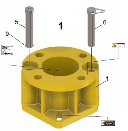
The C-375 Rotary Table by National Oilwell Varco is used for onshore and offshore drilling. Most conductor, riser, and wellhead elements will pass through the C-375 Rotary Table 37-1/2″ table opening.
Armco produces a full line of NATIONAL Rotaries notable for dependability, safety and efficiency, and suitable for any drilling requirement from shallow to the deepest wells. Construction features of NATIONAL Rotaries are developments of nearly half a century of constant design improvement.
Throughout every region in the world and across every area of drilling and production, our family of companies has provided the technical expertise, advanced equipment, and operational support necessary for success—now and in the future.
We believe in purposeful innovation because we see what others do not and we act. Through business innovation, product creation, and service delivery, we are driven to power the industry that powers the world better.
We believe in service above all because our singular goal is to move our customers’ business forward. This drives us to anticipate our customers’ needs and work with them to deliver the finest products and services on time and on budget.
To calculate the overall star rating and percentage breakdown by star, we don’t use a simple average. Instead, our system considers things like how recent a review is and if the reviewer bought the item on Amazon. It also analyzed reviews to verify trustworthiness.

The Kullenberg corer (Kullenberg, 1947; Kelts et al., 1986) is a single-drive, cable-deployed piston corer that is dropped into the sediment from a short distance (typically 0 to 3m), propelled by the momentum of the heavy (~1000 pounds/450 kg) lead weights on the core head. Cores are recovered in steel barrels lined with plastic tubes (standard polycarbonate for the CSD Facility system). The corer drop is triggered when a gravity corer, suspended on a second cable to the side of the Kullenberg corer, enters the sediment and ceases downward travel—thus most Kullenberg cores have an accompanying gravity core that captures the upper sediments that are disturbed by the long corer. Deployed from a cable, the range of water depths is limited only by the length of cable on the winch. However, the immense weight of the system requires a substantial secondary apparatus to handle the corer. A heavy-duty winch and hydraulic system or power supply must be employed to raise and lower the corer, and if long core barrels are used to increase the depth of recovery, a tower or A-frame must be available for deployment and recovery. The weight and bulk of the system can also create hazardous conditions in any deployment circumstances, but particularly if waves cause the vessel to roll and pitch. Thus, a minimum of two experienced crew plus three additional hands is required for safe operation.
The R/V KRKII is a large platform consisting of two 19-foot (5.5m), 950-pound skiff boats bolted together with aluminum deck plates and beams. It can be disassembled and towed behind a heavy-duty truck or shipped in a standard 20-foot shipping container. It was engineered and custom-built for Kullenberg coring, for which it provides a large, stable work surface, a 6.5m quad-leg tower, and 5m long moonpool. At 6m long and 5.5m wide, it is larger and heavier than is necessary for most other types of coring operations, and it is more difficult to ship and requires more time to assemble than more appropriately-sized platforms
This application is a continuation of U.S. patent application Ser. No. 12/813,981 filed Jun. 11, 2010, which is a continuation of U.S. patent application Ser. No. 11/741,330, filed Apr. 27, 2007, now U.S. Pat. No. 7,757,759, which claims benefit of U.S. Provisional Patent Application No. 60/795,344, filed Apr. 27, 2006, all of which are herein incorporated by reference in their entireties. BACKGROUND OF THE INVENTION
In wellbore construction and completion operations, a wellbore is initially formed to access hydrocarbon-bearing formations (i.e., crude oil and/or natural gas) by the use of drilling. Drilling is accomplished by utilizing a drill bit that is mounted on the end of a drill support member, commonly known as a drill string. To drill within the wellbore to a predetermined depth, the drill string is often rotated by a top drive or rotary table on a surface platform or rig, or by a downhole motor mounted towards the lower end of the drill string. After drilling to a predetermined depth, the drill string and drill bit are removed and a section of casing is lowered into the wellbore. An annular area is thus formed between the string of casing and the formation. The casing string is temporarily hung from the surface of the well. A cementing operation is then conducted in order to fill the annular area with cement. Using apparatus known in the art, the casing string is cemented into the wellbore by circulating cement into the annular area defined between the outer wall of the casing and the borehole. The combination of cement and casing strengthens the wellbore and facilitates the isolation of certain areas of the formation behind the casing for the production of hydrocarbons.
A drilling rig is constructed on the earth"s surface to facilitate the insertion and removal of tubular strings (i.e., drill strings or casing strings) into a wellbore. The drilling rig includes a platform and power tools such as an elevator and a spider to engage, assemble, and lower the tubulars into the wellbore. The elevator is suspended above the platform by a draw works that can raise or lower the elevator in relation to the floor of the rig. The spider is mounted in the platform floor. The elevator and spider both have slips that are capable of engaging and releasing a tubular, and are designed to work in tandem. Generally, the spider holds a tubular or tubular string that extends into the wellbore from the platform. The elevator engages a new tubular and aligns it over the tubular being held by the spider. One or more power drives, i.e. a power tong and a spinner, are then used to thread the upper and lower tubulars together. Once the tubulars are joined, the spider disengages the tubular string and the elevator lowers the tubular string through the spider until the elevator and spider are at a predetermined distance from each other. The spider then re-engages the tubular string and the elevator disengages the string and repeats the process. This sequence applies to assembling tubulars for the purpose of drilling, running casing or running wellbore components into the well. The sequence can be reversed to disassemble the tubular string.
Historically, a drilling platform includes a rotary table and a gear to turn the table. In operation, the drill string is lowered by an elevator into the rotary table and held in place by a spider. A Kelly is then threaded to the string and the rotary table is rotated, causing the Kelly and the drill string to rotate. After thirty feet or so of drilling, the Kelly and a section of the string are lifted out of the wellbore and additional drill string is added.
The process of drilling with a Kelly is time-consuming due to the amount of time required to remove the Kelly, add drill string, reengage the Kelly, and rotate the drill string. Because operating time for a rig is very expensive, as much as $500,000 per day, the time spent drilling with a Kelly quickly equates to substantial cost. In order to address these problems, top drives were developed. Top drive systems are equipped with a motor to provide torque for rotating the drilling string. The quill of the top drive is connected (typically by a threaded connection) to an upper end of the drill pipe in order to transmit torque to the drill pipe.
Another method of performing well construction and completion operations involves drilling with casing, as opposed to the first method of drilling and then setting the casing. In this method, the casing string is run into the wellbore along with a drill bit. The drill bit is operated by rotation of the casing string from the surface of the wellbore. Once the borehole is formed, the attached casing string may be cemented in the borehole. This method is advantageous in that the wellbore is drilled and lined in the same trip.
FIG. 1A is a side view of an upper portion of a drilling rig 10 having a top drive 100 and an elevator 35. An upper end of a stack of tubulars 70 is shown on the rig 10. The FIG. shows the elevator 35 engaged with one of the tubulars 70. The tubular 70 is placed in position below the top drive 100 by the elevator 35 in order for the top drive having a gripping device (i.e., spear 200 or torque head 300) to engage the tubular.
FIG. 1B is a side view of a drilling rig 10 having a top drive 100, an elevator 35, and a spider 60. The rig 10 is built at the surface 45 of the wellbore 50. The rig 10 includes a traveling block 20 that is suspended by wires 25 from draw works 15 and holds the top drive 100. The top drive 100 has the spear 200 (alternatively, a torque head 300) for engaging the inner wall (outer wall for torque head 400) of tubular 70 and a motor 140 to rotate the tubular 70. The motor 140 may be either electrically or hydraulically driven. The motor 140 rotates and threads the tubular 70 into the tubular string 80 extending into the wellbore 50. The motor 140 can also rotate a drill string having a drill bit at an end, or for any other purposes requiring rotational movement of a tubular or a tubular string. Additionally, the top drive 100 is shown having a railing system 30 coupled thereto. The railing system 30 prevents the top drive 100 from rotational movement during rotation of the tubular 70, but allows for vertical movement of the top drive under the traveling block 110.
In FIG. 1B, the top drive 100 is shown engaged to tubular 70. The tubular 70 is positioned above the tubular string 80 located therebelow. With the tubular 70 positioned over the tubular string 80, the top drive 100 can lower and thread the tubular into the tubular string. Additionally, the spider 60, disposed in a platform 40 of the drilling rig 100, is shown engaged around the tubular string 80 that extends into wellbore 50.
FIG. 1C illustrates a side view of the top drive 100 engaged to the tubular 70, which has been connected to the tubular string 80 and lowered through the spider 60. As depicted in the FIG., the elevator 35 and the top drive 100 are connected to the traveling block 20 via a compensator 170. The compensator 170 functions similar to a spring to compensate for vertical movement of the top drive 100 during threading of the tubular 70 to the tubular string 80. In addition to its motor 140, the top drive includes a counter 150 to measure rotation of the tubular 70 as it is being threaded to tubular string 80. The top drive 100 also includes a torque sub 160 to measure the amount of torque placed on the threaded connection between the tubular 70 and the tubular string 80. The counter 150 and the torque sub 160 transmit data about the threaded joint to a controller via data lines (not shown). The controller is preprogrammed with acceptable values for rotation and torque for a particular joint. The controller compares the rotation and the torque data to the stored acceptable values.
FIG. 1C also illustrates the spider 60 disposed in the platform 40. The spider 60 comprises a slip assembly 66, including a set of slips 62, and piston 64. The slips 62 are wedge-shaped and are constructed and arranged to slide along a sloped inner wall of the slip assembly 66. The slips 62 are raised or lowered by piston 64. When the slips 62 are in the lowered position, they close around the outer surface of the tubular string 80. The weight of the tubular string 80 and the resulting friction between the tubular string 80 and the slips 62, force the slips downward and inward, thereby tightening the grip on the tubular string. When the slips 62 are in the raised position as shown, the slips are opened and the tubular string 80 is free to move longitudinally in relation to the slips.
FIG. 2A is a cross-sectional view of the spear 200, for coupling the top drive 100 and the tubular 70, in disengaged and engaged positions, respectively. The spear 200 includes a cylindrical body 205, a wedge lock assembly 250, and slips 240 with teeth (not shown). The wedge lock assembly 250 and the slips 240 are disposed around the outer surface of the cylindrical body 200. The slips 240 are constructed and arranged to mechanically grip the inside of the tubular 70. The slips 240 are threaded to piston 270 located in a hydraulic cylinder 210. The piston 270 is actuated by pressurized hydraulic fluid injected through fluid ports 220, 230. Additionally, springs 260 are located in the hydraulic cylinder 210 and are shown in a compressed state. When the piston 270 is actuated, the springs decompress and assist the piston in moving the slips 240. The wedge lock assembly 250 is constructed and arranged to force the slips 240 against the inner wall of the tubular 70 and moves with the cylindrical body 205.
In operation, the slips 240, and the wedge lock assembly 250 of top drive 100 are lowered inside tubular 70. Once the slips 240 are in the desired position within the tubular 70, pressurized fluid is injected into the piston 270 through fluid port 220. The fluid actuates the piston 270, which forces the slips 240 towards the wedge lock assembly 250. The wedge lock assembly 250 functions to bias the slips 240 outwardly as the slips are slid along the outer surface of the assembly, thereby forcing the slips to engage the inner wall of the tubular 70.
FIG. 2B is a cross-sectional view of the spear 200, in the engaged position. The FIG. shows slips 240 engaged with the inner wall of the tubular 70 and a spring 260 in the decompressed state. In the event of a hydraulic fluid failure, the spring 260 can bias the piston 270 to keep the slips 240 in the engaged position, thereby providing an additional safety feature to prevent inadvertent release of the tubular string 80. Once the slips 240 are engaged with the tubular 70, the top drive 100 can be raised along with the cylindrical body 205. By raising the body 205, the wedge lock assembly 250 will further bias the slips 240. With the tubular 70 engaged by the top drive 100, the top drive can be relocated to align and thread the tubular with tubular string 80.
Alternatively, the top drive 100 may be equipped with the torque head 300 instead of the spear 200. The spear 200 may be simply unscrewed from the quill (tip of top drive 100 shown in FIGS. 2A and 2B) and the torque head 300 is screwed on the quill in its place. The torque head 300 grips the tubular 70 on the outer surface instead of the inner surface. FIG. 3 is a cross-sectional view of a prior art torque head 300. The torque head 300 is shown engaged with the tubular 70. The torque head 300 includes a housing 305 having a central axis. A top drive connector 310 is disposed at an upper portion of the housing 305 for connection with the top drive 100. Preferably, the top drive connector 310 defines a bore therethrough for fluid communication. The housing 305 may include one or more windows 306 for accessing the housing"s interior.
The torque head 300 may optionally employ a circulating tool 320 to supply fluid to fill up the tubular 70 and circulate the fluid. The circulating tool 320 may be connected to a lower portion of the top drive connector 310 and disposed in the housing 305. The circulating tool 320 includes a mandrel 322 having a first end and a second end. The first end is coupled to the top drive connector 310 and fluidly communicates with the top drive 100 through the top drive connector 310. The second end is inserted into the tubular 70. A cup seal 325 and a centralizer 327 are disposed on the second end interior to the tubular 70. The cup seal 325 sealingly engages the inner surface of the tubular 70 during operation. Particularly, fluid in the tubular 70 expands the cup seal 325 into contact with the tubular 70. The centralizer 327 co-axially maintains the tubular 70 with the central axis of the housing 205. The circulating tool 320 may also include a nozzle 328 to inject fluid into the tubular 70. The nozzle 328 may also act as a mud saver adapter 328 for connecting a mud saver valve (not shown) to the circulating tool 320.
Optionally, a tubular stop member 330 may be disposed on the mandrel 322 below the top drive connector 310. The stop member 330 prevents the tubular 70 from contacting the top drive connector 310, thereby protecting the tubular 70 from damage. To this end, the stop member 330 may be made of an elastomeric material to substantially absorb the impact from the tubular 70.
One or more retaining members 340 are employed to engage the tubular 70. As shown, the torque head 300 includes three retaining members 340 mounted in spaced apart relation about the housing 305. Each retaining member 340 includes a jaw 345 disposed in a jaw carrier 342. The jaw 345 is adapted and designed to move radially relative to the jaw carrier 342. Particularly, a back portion of the jaw 345 is supported by the jaw carrier 342 as it moves radially in and out of the jaw carrier 342. In this respect, a longitudinal load acting on the jaw 345 may be transferred to the housing 305 via the jaw carrier 342. Preferably, the contact portion of the jaw 345 defines an arcuate portion sharing a central axis with the tubular 70. The jaw carrier 342 may be formed as part of the housing 305 or attached to the housing 305 as part of the gripping member assembly.
Movement of the jaw 345 is accomplished by a piston 351 and cylinder 350 assembly. In one embodiment, the cylinder 350 is attached to the jaw carrier 342, and the piston 351 is movably attached to the jaw 345. Pressure supplied to the backside of the piston 351 causes the piston 351 to move the jaw 345 radially toward the central axis to engage the tubular 70. Conversely, fluid supplied to the front side of the piston 351 moves the jaw 345 away from the central axis. When the appropriate pressure is applied, the jaws 345 engage the tubular 70, thereby allowing the top drive 100 to move the tubular 70 longitudinally or rotationally.
The piston 351 may be pivotably connected to the jaw 345. As shown, a pin connection 355 is used to connect the piston 351 to the jaw 345. A pivotable connection limits the transfer of a longitudinal load on the jaw 345 to the piston 351. Instead, the longitudinal load is mostly transmitted to the jaw carrier 342 or the housing 305. In this respect, the pivotable connection reduces the likelihood that the piston 351 may be bent or damaged by the longitudinal load.
The jaws 345 may include one or more inserts 360 movably disposed thereon for engaging the tubular 70. The inserts 360, or dies, include teeth formed on its surface to grippingly engage the tubular 70 and transmit torque thereto. The inserts 360 may be disposed in a recess 365 as shown in FIG. 3A. One or more biasing members 370 may be disposed below the inserts 360. The biasing members 370 allow some relative movement between the tubular 70 and the jaw 345. When the tubular 70 is released, the biasing member 370 moves the inserts 360 back to the original position. Optionally, the inserts 360 and the jaw recess 365 are correspondingly tapered (not shown).
The outer perimeter of the jaw 345 around the jaw recess 365 may aide the jaws 345 in supporting the load of the tubular 70 and/or tubular string 80. In this respect, the upper portion of the perimeter provides a shoulder 380 for engagement with the coupling 72 on the tubular 70 as illustrated FIGS. 3 and 3A. The longitudinal load, which may come from the tubular 70 string 70,80, acting on the shoulder 380 may be transmitted from the jaw 345 to the housing 305.
A base plate 385 may be attached to a lower portion of the torque head 300. A guide plate 390 may be selectively attached to the base plate 385 using a removable pin connection. The guide plate 390 has an inclined edge 393 adapted and designed to guide the tubular 70 into the housing 305. The guide plate 390 may be quickly adjusted to accommodate tubulars of various sizes. One or more pin holes 392 may be formed on the guide plate 390, with each pin hole 392 representing a certain tubular size. To adjust the guide plate 390, the pin 391 is removed and inserted into the designated pin hole 392. In this manner, the guide plate 390 may be quickly adapted for use with different tubulars.
A typical operation of a string or casing assembly using a top drive and a spider is as follows. A tubular string 80 is retained in a closed spider 60 and is thereby prevented from moving in a downward direction. The top drive 100 is then moved to engage the tubular 70 from a stack with the aid of an elevator 35. The tubular 70 may be a single tubular or could typically be made up of three tubulars threaded together to form a joint. Engagement of the tubular 70 by the top drive 100 includes grasping the tubular and engaging the inner (or outer) surface thereof. The top drive 100 then moves the tubular 70 into position above the tubular string 80. The top drive 100 then threads the tubular 70 to tubular string 80.
The spider 60 is then opened and disengages the tubular string 80. The top drive 100 then lowers the tubular string 80, including tubular 70, through the opened spider 60. The spider 60 is then closed around the tubular string 80. The top drive 100 then disengages the tubular string 80 and can proceed to add another tubular 70 to the tubular string 80. The above-described acts may be utilized in running drill string in a drilling operation, in running casing to reinforce the wellbore, or for assembling strings to place wellbore components in the wellbore. The steps may also be reversed in order to disassemble the tubular string.
When joining lengths of tubulars (i.e., production tubing, casing, drill pipe, any oil country tubular good, etc.; collectively referred to herein as tubulars) for oil wells, the nature of the connection between the lengths of tubing is critical. It is conventional to form such lengths of tubing to standards prescribed by the American Petroleum Institute (API). Each length of tubing has an internal threading at one end and an external threading at another end. The externally-threaded end of one length of tubing is adapted to engage in the internally-threaded end of another length of tubing. API type connections between lengths of such tubing rely on thread interference and the interposition of a thread compound to provide a seal.
For some oil well tubing, such API type connections are not sufficiently secure or leakproof. In particular, as the petroleum industry has drilled deeper into the earth during exploration and production, increasing pressures have been encountered. In such environments, where API type connections are not suitable, it is conventional to utilize so-called “premium grade” tubing which is manufactured to at least API standards but in which a metal-to-metal sealing area is provided between the lengths. In this case, the lengths of tubing each have tapered surfaces which engage one another to form the metal-to-metal sealing area. Engagement of the tapered surfaces is referred to as the “shoulder” position/condition.
Whether the threaded tubulars are of the API type or are premium grade connections, methods are needed to ensure a good connection. One method involves the connection of two co-operating threaded pipe sections, rotating a first pipe section relative to a second pipe section by a power tongs, measuring the torque applied to rotate the first section relative to the second section, and the number of rotations or turns which the first section makes relative to the second section. Signals indicative of the torque and turns are fed to a controller which ascertains whether the measured torque and turns fall within a predetermined range of torque and turns which are known to produce a good connection. Upon reaching a torque-turn value within a prescribed minimum and maximum (referred to as a dump value), the torque applied by the power tongs is terminated. An output signal, e.g. an audible signal, is then operated to indicate whether the connection is a good or a bad connection.
FIG. 4A illustrates one form of a premium grade tubing connection. In particular, FIG. 4A shows a tapered premium grade tubing assembly 400 having a first tubular 402 joined to a second tubular 404 through a tubing coupling or box 406. The end of each tubular 402,404 has a tapered externally-threaded surface 408 which co-operates with a correspondingly tapered internally-threaded surface 410 on the coupling 406. Each tubular 402,404 is provided with a tapered torque shoulder 412 which co-operates with a correspondingly tapered torque shoulder 414 on the coupling 406. At a terminal end of each tubular 402,404, there is defined an annular sealing area 416 which is engageable with a co-operating annular sealing area 418 defined between the tapered portions 410,414 of the coupling 406.
During make-up, the tubulars 402, 404 (also known as pins), are engaged with the box 406 and then threaded into the box by relative rotation therewith. During continued rotation, the annular sealing areas 416, 418 contact one another, as shown in FIG. 4B. This initial contact is referred to as the “seal condition”. As the tubing lengths 402,404 are further rotated, the co-operating tapered torque shoulders 412,414 contact and bear against one another at a machine detectable stage referred to as a “shoulder condition” or “shoulder torque”, as shown in FIG. 4C. The increasing pressure interface between the tapered torque shoulders 412,414 cause the seals 416,418 to be forced into a tighter metal-to-metal sealing engagement with each other causing deformation of the seals 416 and eventually forming a fluid-tight seal.
During make-up of the tubulars 402,404, torque may be plotted with respect to turns. FIG. 5A shows a typical x-y plot (curve 500) illustrating the acceptable behavior of premium grade tubulars, such as the tapered premium grade tubing assembly 400 shown in FIGS. 4A-C. FIG. 5B shows a corresponding chart plotting the rate of change in torque (y-axis) with respect to turns (x-axis). Shortly after the tubing lengths engage one another and torque is applied (corresponding to FIG. 4A), the measured torque increases substantially linearly as illustrated by curve portion 502. As a result, corresponding curve portion 502 aof the differential curve 500 aof FIG. 5B is flat at some positive value.
During continued rotation, the annular sealing areas 416,418 contact one another causing a slight change (specifically, an increase) in the torque rate, as illustrated by point 504. Thus, point 504 corresponds to the seal condition shown in FIG. 4B and is plotted as the first step 504 aof the differential curve 500 a. The torque rate then again stabilizes resulting in the linear curve portion 506 and the plateau 506 a. In practice, the seal condition (point 504) may be too slight to be detectable. However, in a properly behaved make-up, a discernable/detectable change in the torque rate occurs when the shoulder condition is achieved (corresponding to FIG. 4C), as represented by point 508 and step 508 a.
Once the shoulder condition is detected, some predetermined torque value may be added to achieve the terminal connection position (i.e., the final state of a tubular assembly after make-up rotation is terminated). The predetermined torque value is added to the measured torque at the time the shoulder condition is detected.
As indicated above, for premium grade tubulars, a leakproof metal-to-metal seal is to be achieved, and in order for the seal to be effective, the amount of torque applied to affect the shoulder condition and the metal-to-metal seal is critical. In the case of premium grade connections, the manufacturers of the premium grade tubing publish torque values required for correct makeup utilizing a particular tubing. Such published values may be based on minimum, optimum and maximum torque values, minimum and maximum torque values, or an optimum torque value only. Current practice is to makeup the connection to within a predetermined torque range while plotting the applied torque vs. rotation or time, and then make a visual inspection and determination of the quality of the makeup.
It would be advantageous to employ top drives in the make-up of premium tubulars. However, available torque subs (i.e., torque sub 160) for top drives do not possess the required accuracy for the intricate process of making up premium tubulars. Current top drive torque subs operate by measuring the voltage and current of the electricity supplied to an electric motor or the pressure and flow rate of fluid supplied to a hydraulic motor. Torque is then calculated from these measurements. This principle of operation neglects friction inside a transmission gear of the top drive and inertia of the top drive, which are substantial. Therefore, there exists a need in the art for a more accurate top drive torque sub. SUMMARY OF THE INVENTION
Embodiments of the present invention generally relate to a torque sub for use with a top drive. In one embodiment a method of connecting threaded tubular members for use in a wellbore is disclosed. The method includes operating a top drive, thereby rotating a first threaded tubular member relative to a second threaded tubular member; measuring a torque exerted on the first tubular member by the top drive, wherein the torque is measured using a torque shaft rotationally coupled to the top drive and the first tubular, the torque shaft having a strain gage disposed thereon; wirelessly transmitting the measured torque from the torque shaft to a stationary interface; measuring rotation of the first tubular member; determining acceptability of the threaded connection; and stopping rotation of the first threaded member when the threaded connection is complete or if the threaded connection is unacceptable.
In another embodiment, a system for connecting threaded tubular members for use in a wellbore is disclosed. The system includes a top drive operable to rotate a first threaded tubular member relative to a second threaded tubular member; and a torque sub. The torque sub includes a torque shaft rotationally coupled to the top drive; a strain gage disposed on the torque shaft for measuring a torque exerted on the torque shaft by the top drive; and an antenna in communication with the strain gage. The system further includes a turns counter for measuring rotation of the first tubular; an antenna in electromagnetic communication with the torque sub antenna and located at a stationary position relative to the top drive; and a computer. The computer is located at a stationary position relative to the top drive; in communication with the stationary antenna and the turns counter; and configured to perform an operation. The operation includes monitoring the torque and rotation measurements during rotation of the first tubular member relative to the second tubular member; determining acceptability of the threaded connection; and stopping rotation of the first threaded member when the threaded connection is complete or if the computer determines that the threaded connection is unacceptable.
In another embodiment, a system for connecting threaded tubular members for use in a wellbore is disclosed. The system includes a top drive operable to rotate a first threaded tubular member relative to a second threaded tubular member; and a torque sub. The torque sub includes a torque shaft rotationally coupled to the top drive; and a strain gage disposed on the torque shaft for measuring a torque exerted on the torque shaft by the top drive; first and second connectors, each connector rotationally coupled to a respective end of the torque shaft; and first and second links longitudinally coupling the connectors together so that only torque is exerted on the torque shaft. The system further includes a turns counter for measuring rotation of the first tubular.
In another embodiment, a method of connecting threaded tubular members for use in a wellbore is disclosed. The method includes operating a top drive, thereby rotating a first threaded tubular member relative to a second threaded tubular member; measuring a torque exerted on the first tubular member by the top drive, wherein the torque is measured using upper and lower turns counters, each turns counter disposed proximate to a respective longitudinal end of the first tubular; and measuring rotation of the first tubular member, wherein the rotation is measured using the lower turns counter.
In another embodiment, a system for connecting threaded tubular members for use in a wellbore is disclosed. The system includes a top drive operable to rotate a first threaded tubular member relative to a second threaded tubular member; an upper turns counter for measuring rotation of an upper longitudinal end of the first tubular; and a lower turns counter for measuring rotation of a lower longitudinal end of the first tubular. BRIEF DESCRIPTION OF THE DRAWINGS
So that the manner in which the above recited features of the present invention can be understood in detail, a more particular description of the invention, briefly summarized above, may be had by reference to embodiments, some of which are illustrated in the appended drawings. It is to be noted, however, that the appended drawings illustrate only typical embodiments of this invention and are therefore not to be considered limiting of its scope, for the invention may admit to other equally effective embodiments.
FIG. 1A is a side view of a prior art drilling rig having a top drive and an elevator. FIG. 1B is a side view of a prior art drilling rig having a top drive, an elevator, and a spider. FIG. 1C illustrates a side view of a top drive engaged to a tubular, which has been lowered through a spider.
FIG. 2A is a cross-sectional view of a spear, for coupling a top drive and a tubular, in a disengaged position. FIG. 2B is a cross-sectional view of a spear, for coupling a top drive and a tubular, in an engaged position.
FIG. 4A is a partial cross section view of a connection between threaded premium grade members. FIG. 4B is a partial cross section view of a connection between threaded premium grade members in which a seal condition is formed by engagement between sealing surfaces. FIG. 4C is a partial cross section view of a connection between threaded premium grade members in which a shoulder condition is formed by engagement between shoulder surfaces.
FIG. 5A is a plot of torque with respect to turns for a premium tubular connection. FIG. 5B is a plot of the rate of change in torque with respect to turns for a premium tubular connection.
FIG. 6 is an isometric view of a torque sub, according to one embodiment of the present invention. FIG. 6A is a side view of a torque shaft of the torque sub. FIG. 6B is an end view of the torque shaft with a partial sectional view cut along line 6B-6B of FIG. 6A. FIG. 6C is a cross section of FIG. 6A. FIG. 6D is an isometric view of the torque shaft. FIG. 6E is a top view of a strain gage. FIG. 6F is a partial section of a reduced diameter portion of the torque shaft showing the strain gage of FIG. 6E mounted thereon. FIG. 6G is a schematic of four strain gages in a Wheatstone bridge configuration. FIG. 6H is a schematic of strain gages mounted on the tapered portion of the torque shaft. FIG. 6I is an electrical diagram showing data and electrical communication between the torque shaft and a housing of the torque sub.
FIG. 9 is a side view of a top drive system employing a torque meter, according to another alternative embodiment of the present invention. FIG. 9A is an enlargement of a portion of FIG. 9. FIG. 9B is an enlargement of another portion of FIG. 9.
FIG. 6 is an isometric view of a torque sub 600, according to one embodiment of the present invention. The torque sub 600 includes a housing 605, a torque shaft 610, an interface 615, and a controller 620. The housing 605 is a tubular member having a bore therethrough. The housing 605 includes a bracket 605 afor coupling the housing 605 to the railing system 30, thereby preventing rotation of the housing 605 during rotation of the tubular, but allowing for vertical movement of the housing with the top drive 100 under the traveling block 110. The interface 615 and the controller 620 are both mounted on the housing 605. The housing 605 and the torque shaft 610 are made from metal, preferably stainless steel. The interface 615 is made from a polymer. Preferably, the elevator 35 (only partially shown) is also mounted on the housing 605, although this is not essential to the present invention.
FIG. 6A is a side view of the torque shaft 610 of the torque sub 600. FIG. 6B is an end view of the torque shaft 610 with a partial sectional view cut along line 6B-6B of FIG. 6A. FIG. 6C is a cross section of FIG. 6A. FIG. 6D is an isometric view of the torque shaft 610. The torque shaft 610 is a tubular member having a flow bore therethrough. The torque shaft 610 is disposed through the bore of the housing 605 so that it may rotate relative to the housing 605. The torque shaft 610 includes a threaded box 610 a, a groove 610 b, one or more longitudinal slots 610 c(preferably two), a reduced diameter portion 610 d, and a threaded pin 610 e, a metal sleeve 610 f, and a polymer (preferably rubber, more preferably silicon rubber) shield 610 g.
The threaded box 610 areceives the quill of the top drive 100, thereby forming a rotational connection therewith. The pin 610 eis received by either a box of the spear body 205 or the top drive connector 310 of the torque head 300, thereby forming a rotational connection therewith. The groove 610 breceives a secondary coil 630 b(see FIG. 6I) which is wrapped therearound. Disposed on an outer surface of the reduced diameter portion 610 dare one or more strain gages 680 (see FIGS. 6E-6H). The strain gages 680 are disposed on the reduced diameter portion 610 dat a sufficient distance from either taper so that stress/strain transition effects at the tapers are fully dissipated. The slots 610 cprovide a path for wiring between the secondary coil 630 band the strain gages 680 and also house an antenna 645 a(see FIG. 6I).
The shield 610 gis disposed proximate to the outer surface of the reduced diameter portion 610 d. The shield 610 gmay be applied as a coating or thick film over strain gages 680. Disposed between the shield 610 gand the sleeve 610 fare electronic components 635,640 (see FIG. 6I). The electronic components 635,640 are encased in a polymer mold 630 (see FIG. 6I). The shield 610 gabsorbs any forces that the mold 630 may otherwise exert on the strain gages 680 due to the hardening of the mold. The shield 610 galso protects the delicate strain gages 680 from any chemicals present at the wellsite that may otherwise be inadvertently splattered on the strain gages 680. The sleeve 610 fis disposed along the reduced diameter portion 610 d. A recess is formed in each of the tapers to seat the shield 610 f. The sleeve 610 fforms a substantially continuous outside diameter of the torque shaft 610 through the reduced diameter portion 610 d. Preferably, the sleeve 610 fis made from sheet metal and welded to the shaft 610. The sleeve 610 falso has an injection port formed therethrough (not shown) for filling fluid mold material to encase the electronic components 635,640.
FIG. 6E is a top view of the strain gage 680. FIG. 6F is a partial section of the reduced diameter portion 610 dof the torque shaft 610 showing the strain gage of FIG. 6E mounted thereon. FIG. 6G is a schematic of four strain gages 680 in a Wheatstone bridge 685 configuration. FIG. 6H is a schematic of strain gages 680 t,wmounted on the tapered portion 610 dof the torque shaft 610.
Preferably, each strain gage 680 is made of a thin foil grid 682 and bonded to the tapered portion 610 dof the shaft 610 by a polymer support 684, such as an epoxy glue. The foil 682 strain gauges 680 are made from metal, such as platinum, tungsten/nickel, or chromium. The sensitive part of each strain gage 680 is along the straight part (parallel to longitudinal axis o-x) of the conducting foil 682. When elongated, this conducting foil 682 increases in resistance. The resistance may be measured by connecting the strain gage 680 to an electrical circuit via terminal wires 683. Two gages 680 are usually configured in a Wheatstone bridge 685 to increase sensitivity. Two more gages 680 not submitted to the strain are added to compensate for temperature variation. The longitudinal load acting on the torque shaft 610 is measured by orientating a strain gage 680 wwith its longitudinal axis o-x parallel to the longitudinal axis of the torque shaft 610. The torque acting on the torque shaft 610 is measured by orienting a strain gage 680 twith its longitudinal axis o-x at a forty-five degree angle relative to the longitudinal axis of the torque shaft 610 and another strain gage 680 tat a negative forty-five degree angle relative to the longitudinal axis of the torque shaft 610. Preferably, each of the strain gages 680 t,680 t,680 wis a Wheatstone bridge 685 made up of four strain gages 680. Alternatively, semi-conductor strain gauges (not shown) or piezoelectric (crystal) strain gages may be used in place of the foil strain gauges 680. Alternatively, only a single strain gage 680 tmay be disposed on the shaft 610.
FIG. 6I is an electrical diagram showing data and electrical communication between the torque shaft 610 and the housing 605 of the torque sub 600. A power source 660 is provided. The power source 660 may be a battery pack disposed in the controller 620, an-onsite generator, or utility lines. The power source 660 is electrically coupled to a sine wave generator 650. Preferably, the sine wave generator 650 will output a sine wave signal having a frequency less than nine kHz to avoid electromagnetic interference. The sine wave generator 650 is in electrical communication with a primary coil 630 aof an electrical power coupling 630.
The electrical power coupling 630 is an inductive energy transfer device. Even though the coupling 630 transfers energy between the stationary interface 615 and the rotatable torque shaft 610, the coupling 630 is devoid of any mechanical contact between the interface 615 and the torque shaft 610. In general, the coupling 630 acts similar to a common transformer in that it employs electromagnetic induction to transfer electrical energy from one circuit, via its primary coil 630 a, to another, via its secondary coil 630 b, and does so without direct connection between circuits. The coupling 630 includes the secondary coil 630 bmounted on the rotatable torque shaft 610. The primary 630 aand secondary 630 bcoils are structurally decoupled from each other.
The primary coil 630 amay be encased in a polymer 627 a, such as epoxy. A coil housing 627 bmay be disposed in the groove 610 b. The coil housing 627 bis made from a polymer and may be assembled from two halves to facilitate insertion around the groove 610 b. The secondary coil 630 bmay then be wrapped around the coil housing 627 bin the groove 610 b. Optionally, the secondary coil 630 bis then molded in the coil housing 627 bwith a polymer. The primary 630 aand secondary coils 630 bare made from an electrically conductive material, such as copper, copper alloy, aluminum, or aluminum alloy. The primary 630 aand/or secondary 630 bcoils may be jacketed with an insulating polymer. In operation, the alternating current (AC) signal generated by sine wave generator 650 is applied to the primary coil 630 a. When the AC flows through the primary coil 630 a, the resulting magnetic flux induces an AC signal across the secondary coil 630 b. The induced voltage causes a current to flow to rectifier and direct current (DC) voltage regulator (DCRR) 635. A constant power is transmitted to the DCRR 635, even when torque shaft 610 is rotated by the top drive 100. The primary coil 630 aand the secondary coil 630 bhave their parameters (i.e., number of wrapped wires) selected so that an appropriate voltage may be generated by the sine wave generator 650 and applied to the primary coil 630 ato develop an output signal across the secondary coil 630 b. Alternatively, conventional slip rings, roll rings, or transmitters using fluid metal may be used instead of the electrical coupling 630 or a battery pack may be disposed in the torque shaft 610, thereby eliminating the need for the electrical coupling 630 or alternatives.
The DCRR 635 converts the induced AC signal from the secondary coil 630 binto a suitable DC signal for use by the other electrical components of the torque shaft 610. The DCRR outputs a first signal to the strain gages 680 and a second signal to an amplifier and microprocessor controller (AMC) 640. The first signal is split into sub-signals which flow across the strain gages 680, are then amplified by the amplifier 640, and are fed to the controller 640. The controller 640 converts the analog signals from the strain gages 680 into digital signals, multiplexes them into a data stream, and outputs the data stream to a modem 640 (preferably a radio frequency modem). The modem 640 modulates the data stream for transmission from antenna 645 a. The antenna 645 atransmits the encoded data stream to an antenna 645 bdisposed in the interface 615. Alternatively, the analog signals from the strain gages may be multiplexed and modulated without conversion to digital format. Alternatively, conventional slip rings, an electric swivel coupling, roll rings, or transmitters using fluid metal may be used to transfer data from the torque shaft 610 to the interface 615.
Rotationally coupled to the torque shaft 610 is a turns gear 665. Disposed in the interface 615 is a proximity sensor 670. The gear/sensor 665,670 arrangement is optional. Various types of gear/sensor 665,670 arrangements are known in the art and would be suitable. The proximity sensor 665 senses movement of the gear 670. Preferably, a sensitivity of the gear/sensor 665,670 arrangement is one-tenth of a turn, more preferably one-hundredth of a turn, and most preferably one-thousandth of a turn. Alternatively a friction wheel/encoder device (see FIG. 9) or a gear and pinion arrangement may be used instead of a gear/sensor arrangement. A microprocessor controller 655 may provide power to the proximity sensor 670 and receives an analog signal indicative of movement of the gear 665 therefrom. The controller 655 may convert the analog signal from the proximity sensor 670 and convert it to a digital format.
The antenna 645 bsends the received data stream to a modem 655. The modem 655 demodulates the data signal and outputs it to the controller 655. The controller 655 de-codes the data stream, combines the data stream with the turns data, and re-formats the data stream into a usable input (i.e., analog, field bus, or Ethernet) for a make-up computer system 706 (see FIG. 7). The controller 655 is also powered by the power source 660. The controller 655 may also process the data from strain gages 680 and proximity sensor 665 to calculate respective torque, longitudinal load, and turns values therefrom. The controller 655 may also be connected to a wide area network (WAN) (preferably, the Internet) so that office engineers/technicians may remotely communicate with the controller 655. Further, a personal digital assistant (PDA) may also be connected to the WAN so that engineers/technicians may communicate with the controller 655 from any worldwide location.
The interface controller 655 may also send data to the torque shaft controller 640 via the antennas 645 a, b. A separate channel may be used for communication from the interface controller 655 to the torque shaft controller 640. The interface controller 655 may send commands to vary operating parameters of the torque shaft 610 and/or to calibrate the torque shaft 610 (i.e., strain gages 680 t, w) before operation. In addition, the interface controller 655 may also control operation of the top drive 100 and/or the torque head 300 or the spear 200.
FIG. 7 is a block diagram illustrating a tubular make-up system implementing the torque sub of FIG. 6. Generally, the tubular make-up system 700 includes the top drive 100, torque sub 600, and the computer system 706. A computer 716 of the computer system 706 monitors the turns count signals and torque signals 714 from torque sub 600 and compares the measured values of these signals with predetermined values. In one embodiment, the predetermined values are input by an operator for a particular tubing connection. The predetermined values may be input to the computer 716 via an input device, such as a keypad, which can be included as one of a plurality of input devices 718.
Illustrative predetermined values which may be input, by an operator or otherwise, include a delta torque value 724, a delta turns value 726, minimum and maximum turns values 728 and minimum and maximum torque values 730. During makeup of a tubing assembly, various output may be observed by an operator on output device, such as a display screen, which may be one of a plurality of output devices 720. The format and content of the displayed output may vary in different embodiments. By way of example, an operator may observe the various predefined values which have been input for a particular tubing connection. Further, the operator may observe graphical information such as a representation of the torque rate curve 500 and the torque rate differential curve 500 a. The plurality of output devices 720 may also include a printer such as a strip chart recorder or a digital printer, or a plotter, such as an x-y plotter, to provide a hard copy output. The plurality of output devices 720 may further include a horn or other audio equipment to alert the operator of significant events occurring during make-up, such as the shoulder condition, the terminal connection position and/or a bad connection.
Upon the occurrence of a predefined event(s), the computer system 706 may output a dump signal 722 to automatically shut down the top drive unit 100. For example, dump signal 722 may be issued upon detecting the terminal connection position and/or a bad connection.
The comparison of measured turn count values and torque values with respect to predetermined values is performed by one or more functional units of the computer 716. The functional units may generally be implemented as hardware, software or a combination thereof. By way of illustration of a particular embodiment, the functional units are described as software. In one embodiment, the functional units include a torque-turns plotter algorithm 732, a process monitor 734, a torque rate differential calculator 736, a smoothing algorithm 738, a sampler 740, a comparator 742, and a deflection compensator 752. The process monitor 734 includes a thread engagement detection algorithm 744, a seal detection algorithm 746 and a shoulder detection algorithm 748. It should be understood, however, that although described separately, the functions of one or more functional units may in fact be performed by a single unit, and that separate units are shown and described herein for purposes of clarity and illustration. As such, the functional units 732-742,752 may be considered logical representations, rather than well-defined and individually distinguishable components of software or hardware.
The deflection compensator 752 includes a database of predefined values or a formula derived therefrom for various torque and system deflections resulting from application of various torque on the top drive unit 100. These values (or formula) may be calculated theoretically or measured empirically. Since the top drive unit 100 is a relatively complex machine, it may be preferable to measure deflections at various torque since a theoretical calculation may require extensive computer modeling, i.e. finite element analysis. Empirical measurement may be accomplished by substituting a rigid member, i.e. a blank tubular, for the premium grade assembly 400 and causing the top drive 100 to exert a range of torques corresponding to a range that would be exerted on the tubular grade assembly to properly make-up a connection. In the case of the top drive unit 100, the blank may be only a few feet long so as not to compromise rigidity. The torque and rotation values provided by torque sub 600, respectively, would then be monitored and recorded in a database. The test may then be repeated to provide statistical samples. Statistical analysis may then be performed to exclude anomalies and/or derive a formula. The test may also be repeated for different size tubulars to account for any change in the stiffness of the top drive 100 due to adjustment of the units for different size tubulars. Alternatively, only deflections for higher values (i.e. at a range from the shoulder condition to the terminal condition) need be measured.
Deflection of tubular member 402, preferably, will also be added into the system deflection. Theoretical formulas for this deflection may readily be available. Alternatively, instead of using a blank for testing the top drive, the end of member 402 distal from the top drive may simply be locked into a spider. The top drive 100 may then be operated across


 8613371530291