
heavy duty cnc rotary table free sample
A turbo among rotary tables – the new FIBRODYN DA direct driven rotary tables with torque motor are optimally suited for all handling and assembly applications that require the shortest indexing times and flexible positioning. Thanks to its measuring system directly in the rotary table axis, any position can be moved to with the highest precision. The slim design with its very space-saving, compact construction and its fitted boreholes makes it very easy to integrate the rotary tale into your system. FIBRODYN DA is also available as decentralized stand-alone solution with integrated control. In this version, it offers the ideal opportunity to save a separate external NC control to minimize the implementation and start-up costs and to realize small machines without complex peripherals. The rotary tables are lifetime lubricated and maintenance free.

Sometimes when using a CNC router to make cuts it is necessary to change out tooling. With a single tool spindle this operation can take valuable production time and introduces another point in the production process for human error to be introduced.
The PHANTOM CNC SYSTEM-ATC CNC machine reduces production time by automatically changing cutters between tool paths, thus eliminating the need for the CNC operator to change and zero tools individually. The ATC feature allows our router to do the full job, even when different tooling is required to make different types of cuts. Signs and complex 3D carvings are a good example of this. A machine equipped with an ATC can perform operations normally done on other pieces of equipment, eliminating the need for additional machines in the shop.
Vacuum tables are common in cnc routers. Besides its firm holding, a vacuum table can also flatten boards and make closed shaped cut-outs more easily without obstructions like clamps in the way of the toolpath.
The vacuum table surface is made from Phenol Resin Panels ( Bakelite ) instead of Hard PVC Boards for better strength and wear resistance. This will provide a longer lifespan in a tough shop environment. The vacuum table can be control with 4 independent gate valves.
PHANTOM CNC SYSTEMS T ATC CNC uses a 1.5M helical tooth rack and pinion system. This allows for smooth high speed, high precision and low noise operation. We use PMI 25 Linear guides with flange sliders on all axis.
We use a stand alone control system that is completely separate of a PC controller. This allows full control of the CNC without worry of Windows updates or controller software updates that could slow down your business.
CNC Routers adopt advanced open-architecture CNC controllers, with built-in high-performance industry computers, LCD screens, and combining with servo axis, spindle, and MPG axis, built-in PLC ( Programmable Logic Controller ) and USB interface, Compact Flash Card reading device.
The roller pressure is distributed on both sides of the spindle, which can effectively prevent the material from moving on the table when processing small materials or materials that are not easily suctioned or clamped. Rollers provide 600lbs of downward pressure.
ATC CNC router has an automatic tool change function including carousel tool change type and linear tool change type. According to the processing requirements, automatic tool change can be realized without manual participation, which further improves the machining efficiency. To know ATC CNC router machine price information, you can leave a message through our website or directly call us. To learn more about our ATC CNC Router, browse our range below:
ATC 4th Rotary device: Rotary could be added on the side of the machine table or put it on the machine table, depends on your using habit. You can choose the proper rotary"s diameter and length according to your materials. It"s mainly be used for processing some round or square materials.
Rotary on Table: 4-Axis rotary table assembly comes complete with a 3-jaw chuck, tailstock, and guide track for easy tailstock movement and center alignment. The addition of 4-axis rotary table assembly adds greater functionality to the machine"s capabilities allowing for 4-axis cutting in both 2D and 3D carving and indexing functions.
Full Length 4-Axis rotary table assembly comes complete with a 3-jaw chuck, tailstock, and guide track for easy tailstock movement and center alignment. The addition of 4-axis rotary table assembly adds greater functionality to the machine"s capabilities allowing for 4-axis cutting in both 2D and 3D carving and indexing functions. (PHANTOM CNC SYSTEM rotary size has 0-3”, 0-4”, 0-6”, 0-7.9”, diameter rotary axis for your choice).

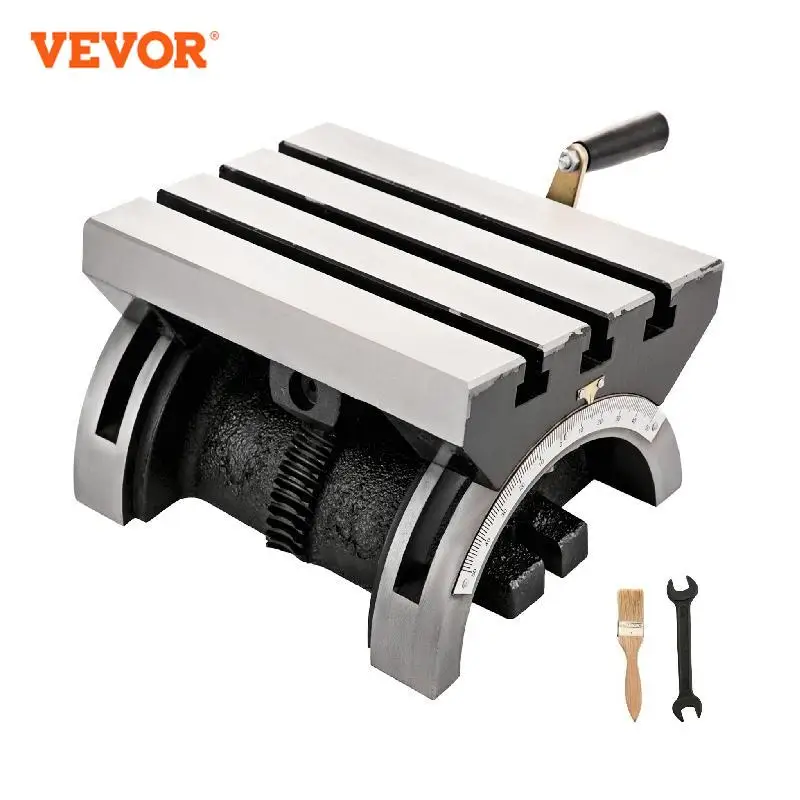
A rotary table is a precision work positioning device used in metalworking. It enables the operator to drill or cut work at exact intervals around a fixed (usually horizontal or vertical) axis. Some rotary tables allow the use of index plates for indexing operations, and some can also be fitted with dividing plates that enable regular work positioning at divisions for which indexing plates are not available. A rotary fixture used in this fashion is more appropriately called a dividing head (indexing head).
The table shown is a manually operated type. Powered tables under the control of CNC machines are now available, and provide a fourth axis to CNC milling machines. Rotary tables are made with a solid base, which has provision for clamping onto another table or fixture. The actual table is a precision-machined disc to which the work piece is clamped (T slots are generally provided for this purpose). This disc can rotate freely, for indexing, or under the control of a worm (handwheel), with the worm wheel portion being made part of the actual table. High precision tables are driven by backlash compensating duplex worms.
The ratio between worm and table is generally 40:1, 72:1 or 90:1 but may be any ratio that can be easily divided exactly into 360°. This is for ease of use when indexing plates are available. A graduated dial and, often, a vernier scale enable the operator to position the table, and thus the work affixed to it with great accuracy.
Rotary tables are most commonly mounted "flat", with the table rotating around a vertical axis, in the same plane as the cutter of a vertical milling machine. An alternate setup is to mount the rotary table on its end (or mount it "flat" on a 90° angle plate), so that it rotates about a horizontal axis. In this configuration a tailstock can also be used, thus holding the workpiece "between centers."
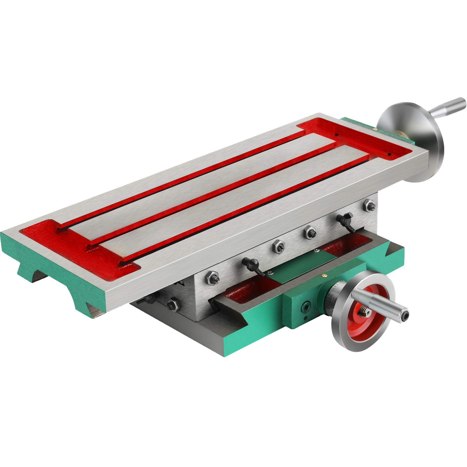
With the table mounted on a secondary table, the workpiece is accurately centered on the rotary table"s axis, which in turn is centered on the cutting tool"s axis. All three axes are thus coaxial. From this point, the secondary table can be offset in either the X or Y direction to set the cutter the desired distance from the workpiece"s center. This allows concentric machining operations on the workpiece. Placing the workpiece eccentrically a set distance from the center permits more complex curves to be cut. As with other setups on a vertical mill, the milling operation can be either drilling a series of concentric, and possibly equidistant holes, or face or end milling either circular or semicircular shapes and contours.
with the addition of a compound table on top of the rotary table, the user can move the center of rotation to anywhere on the part being cut. This enables an arc to be cut at any place on the part.
Additionally, if converted to stepper motor operation, with a CNC milling machine and a tailstock, a rotary table allows many parts to be made on a mill that otherwise would require a lathe.
Rotary tables have many applications, including being used in the manufacture and inspection process of important elements in aerospace, automation and scientific industries. The use of rotary tables stretches as far as the film and animation industry, being used to obtain accuracy and precision in filming and photography.

For situations that require horizontal rotary tables, CNC rotary tables, positioning rotary tables, indexing rotary tables, turning rotary tables, direct drive rotary tables with high accuracy and heavy loading capacities, and are suitable for heavy machining and metrology applications. Large rotary tables is one of our specialties!
Preloaded axial-radial roller bearings are incorporated, to provide high rigidity in both planes. Sensitivity and fine positioning are ensured. We are experts in the design of horizontal rotary tables, positioning rotary tables, indexing rotary tables, turning rotary tables and large rotary tables.
The modular design permits freedom to match application requirements. The worm gear drive is specially configured for maximum torque and minimum (adjustable) backlash. Our horizontal rotary tables are designed for production jobs, heavy duty machining, large part machining, heavy load capacity machining.
A CNC rotary table is the precision positioning accessory that can provide a reliable 4th axis or even 5th axis for modern machining centers. Utilizing a computer-controlled rotary table can turn the original 3-axis machine tools into 5-axis CNC machines, expanding the accuracy as well as decreasing the costs while performing complex machining operations at one time.
A CNC rotary table is the precision positioning accessory that can provide reliable 4 or even 5 axis cutting operation capabilities for modern machining centers. Utilizing it can turn the original 3-axis machine tools into 5-axis CNC machines, expanding the accuracy as well as decreasing the costs while performing complex machining operations.
Rotary tables typically have rigid frames and coatings, and also excellent torque capacity, which makes the small device flexible and effective for a wide variety of turning, milling, drilling, and more metalworking operations. The easy setup and seamless interface allow the operators to easily add the rotary table to fit their 4-axis or 5-axis applications. .
The working principle is similar to the basic rotary tables, which is to support the workpiece by accurately rotating the workpieces on the axis in order to locate the parts for high precision tooling. Under rapid rotation, which is driven by CNC instructions, the cutting tools of larger machine tools or machining centers can remove the material and add the feature to the products at exact intervals. On rotary tables, there are vertical and horizontal axes for various tools to perform these high-performance metalworks. To enhance the accuracy and flexibility, there are models that employ additional dividing plates and come with additonal material handling mechanisms and features.
Since 4-axis and 5-axis machining is increasingly popular today, adding the CNC rotary table as the 4th axis is an ideal solution to easily open up more complex machining options at a lower cost. Due to the arrangement, they are widely also called the 4th or 5th axis or tilt rotary. The 4th axis, which is the rotational operational direction, is added to the original three linear axes which are known as X-axis, Y-axis, Z-axis. In some cases, there are two rotational axes add to the original 3-axis machining center, achieving utmost accuracy as well as effective multiple face cutting to reach the difficult area on the surface. Rotary tables are usually mounted parallel to the ground or the bed, with the platter rotating around the vertical axis, for example with the most common vertical milling machine combination. Sometimes the machining application requires an alternative setup with the table mountet on its end so that it rotates around the horizontlal axis. Often, a tailstock is used in this configuration. Virtually all models today come with a clamping kit to mount it onto the bed of your machine tool.
The function of the high precision rotary table is also to rotate the workpiece so the cutting tool can create the contour we desired out of the workpiece. However, a rotary table with higher precision has the ability to achieve great accuracy just as its name implies. There is also a major misconception between the resolution and the accuracy.
A common example is that if a digital readout displays to four decimal places, then the high precision rotary table must also be capable of achieving the accuracy to that same value. Even though for higher accuracy to be achieved, the resolution has to also be high, but there is no guarantee that the accuracy is going to be high. The accuracy is the concept which is the difference between the actual position and the position measured by a reference measurement device. The feedback mechanism such as the rotary encoder, and the drive mechanism can influence the accuracy of the advanced rotary table.
A CNC rotary table can provide great rigidity for stable machining operations. It consists of the worktable where the metal parts are held, the rigid bearing that withstands the forces and loads during the rotation, the solid base which is used for attaching the rotary table to the machining center or other equipment, the motor, and the CNC system.
The worktable is the tooling surface where the workpieces are machined after accurate positioning. The worm gearing is the core mechanism of the table, which mesh with the steel worm which is submerged in the lubricants. Both the rigid bearings and the worm gears have large diameters. Excellent concentricity is the key to smooth operation, durability, and most importantly, accuracy. Driven by a computer and electric motor, the worktable can position the materials at exact intervals. For more flexible or critical operations, dividing plates can be added to this component.
A CNC system regulates the simultaneous 4-axis motion of the rotary table. The instructions are programmed and transmitted via CAD software, reducing the time for adjustment and monitoring by human workers.
There are currently several different types and models available in the industries. Each of them possess its own traits and abilities. Let us take a look at the most common ones other than standard three axis tables
The 4 axis CNC rotary table will process the workpieces by holding them in the same position while the cutting tool performs along the XYZ plane to trim away the unwanted material. In general, a 4 axis model is very versatile equipment that can be used for several different industrial processes such as engraving curved surfaces, continuous cutting, and intermittent cutting. Besides, people can also add other devices such as cam machining, blade machining, and helical grooves to the 4 axes rotary table. Such a feature is simply impossible to achieve with the machining center which has only 3 axes.
Besides the 4 axis ones, there are also 5 axis models. They have the ability to allow the workpiece to be processed automatically from five sides at one time. people usually utilized the 5 axes rotary table in the industries such as the automobile, the aerospace, and the boating industries. The reason that the 5 axes rotary table is commonly used in heavy industries is that the 5 axis machining is an important technique to be used when the components need better intricacy and quick precision. All of these have more than three axes are called the multi-axis rotary table.
The installation method of the precision rotary table can be horizontal, vertical or inverted. When installed horizontally, the workbench surface is in a flat, vertical and horizontal position. When installed vertically, a rotary table is installed so that the surface of it can run up and down. In the reverse layout, itcan be rotated upside down in a horizontal position. The location of the drive of the rotary table can depend on the mount. The drive can be placed on the back, below, on the top or on the side.
When mounted horizontally, the spinning table top drive is positioned above the table floor. When the rotary table is horizontally placed, the side-mounted drive is located on the edge of the table board. The driving mechanism of the rotary table may be manual, electrical, pneumatic, hydraulic or non-driven. For manual revolving workbenches, release the workbenches and manually spin the workbenches with the crank.
Since the metalwork is driven by software, the preferred frameworks can be programmed and adapted by the rotary table. Saving both the cost and the room makes themis the ideal solution for potential users who don’t want to install larger equipment and new machines which may take up a great room for a wide variety of machining applications.
Another benefit is the utmost movements can be completed precisiely and faster. There are more favorable positions, operation angles as well as accessible machining that can be achieved through the technology. The complex operations are suitable for blade, helical grooves production, and other applications required to add complex features or require critical inspection in machining processes like the manufacturing of aerospace, automotive parts, and scientific equipment.
Addding a rotational table saves time because the extra finishing jobs or other sub-operations can also be performed at one time in the machining center.
A rotary table can be used in many applications including manufacturing, inspection, and assembly. Indicators are used, for example, for assembly, manufacturing, and bottling equipment. They typically use a single item in workspaces or move relatively small layouts of items around stations for sequential work or assembly.
In automated assembly machines, the rotary tables implementation is widespread, and choosing the right mechanism is important for both improving efficiency and reducing the cost of this vital component. This guide discusses two common devices for rotating indexing and offers guidance on the right range. There are several ways to get mass mobilization when it comes to the development of rotary indexing tables. Regardless of whether the load or load in centuries of thousands of kgm2 is incredibly light. When choosing a robust rotary index solution that will match or meet your standards, there are several factors to take into account when spinning, elevating, or pushing.
When determining the influencing factors on the postitioning accuracy, the first thing to look at is the mechanical properties of the table itself. A rotary table contains six degrees of freedom. Each of these movements increases the total risk of positioning errors. Usually, a rotary table is driven by a worm gear, which is connected to the motor through a rotary encoder on the back. The position of the table can be determined by the number of pulses transmitted from the encoder to the control device.
The four main sources of error due to the semi-closed position loop are geometric errors, thermal deformation, elasticity, and wear. The sum of these errors is called angular positioning error. To greatly reduce the angular positioning error, the ideal position for installing the angle encoder is on the rotating shaft under test. The angle encoder is installed under the rotary table, and the rotary encoder is installed under the rear motor, the position loop is now considered a closed-loop system.
In the actual test, by selecting specific components, motion index drive, servo rotary indexer, the measurement accuracy is as high as 5-6 microns. These are not the results approved by Motion Index Drives, but the results of customer certification. When starting and stopping large amounts of data, it is important to know how fast it takes to stop the application with large amounts of data.
Backlash in the positioning process is a big issue – when it comes to the beginning and stopping volumes, it"s crucial to know how quickly you need to avoid the mass of your rotary indexing table applications. In a less rigid system or where there is an increased backlash, quicker start-ups and stops can cause a lot of control issues. When shifting a mass, whether rotary or linear, starting and stopping in a system with several minutes of backlash arc will create a lot of back-and-forth motion within the gearing system. The effect is a power that can be difficult and probably hard to quantify. In comparison, as the gear head is used for rotational applications, the more the mass is from the axis of rotation, the further the backlash is magnified.
The backlash may not be a concern in systems where deceleration times are incredibly long. In the case of cam indexers, there is " Zero Backlash." The cam indexer and rotary table dynamics give an incredibly rigid, highly regulated framework. A modern cam indexer system is capable of withstanding short cycle times with stop times in milliseconds.
So you want to get the smart manufacturing going but are not sure of what to look for in rotary tables. The information provided in this section may be able to help. The primary factor is to determine the mass snapshot of inactivity. This is often overlooked when measuring a rotary table for the machine.
Another significant factor is the size of the workpiece being rotated, including how big it is and how substantial it is. You want your rotary tables to be large enough to handle enormous pieces. This is where tilling rotary tables may become handy so that the pieces can be handled without causing interior harm. They allow the quickening and decelerating of machining at appropriate rates.
The last factor is accuracy, the applications for which, for instance, pivoting a gigantic part to allow welding highlights on it where the individual stop positions can be genuinely free. On an additional note, when choosing direct drive rotary tables, factors that you should consider when selecting a rotary table for your CNC machinery include accuracy, backlash, mass moment of inertia, acceleration and deceleration, speed, and environment.
Cam indexers are an omnipresent tool used for several decades for rotary indexing tables. They are suitable for applications that often index the same angle and need a high degree of accuracy at a relatively low cost. To place the load, a cam indexer uses a mechanical cam. A math curve is pushed onto the cam and provides incredibly smooth and repeatable movement.
Another popular alternative is a fully programmable rotary index table. A rotary table is advantageous in two different situations. Firstly, a versatile movement pattern is important. An example is if two components are running on one computer, each of which requires different index patterns. For incredibly fast placement accompanied by a long period, another condition that matches the servo pointer is. The need to accelerate the camshaft while the cam indexing mechanism was operating before starting the output movement reduced the on-demand cam indexer. Acceleration of the camshaft is possible, but there is a delay before the movement begins. There are realistic restrictions.
With an indexing table, the output rotates as soon as the servo starts moving. This is not difficult for a continuous cam indexer or a zero-backlash servo indexer, but it can also be difficult for an on-demand cam indexer. For applications with high-speed servo indexing, smooth movements are crucial. A zero-backlash preloaded reducer can achieve this. The ideal alternative for correct positioning with high dynamic response would be the zero-backlash reel drive system.
Application parameters, like a moment of inertia, indexing angle, indexing period, and residence time, are required for each indexer style. The rotary indexing table for the application should also be sized correctly by a reputable manufacturer.


 8613371530291