
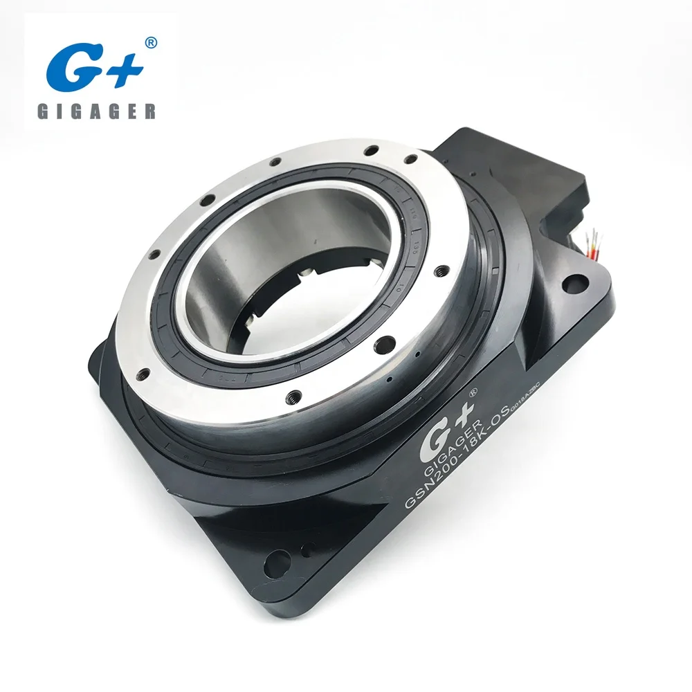
hollow rotary table free sample
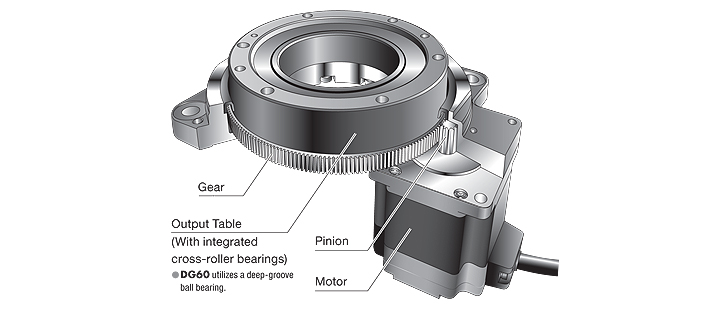
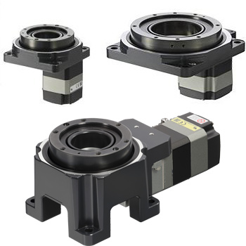
The DGII Series is a line of of products that combine a high rigidity hollow rotary table with an AlphaStep closed loop stepper motor and driver package. It retains the ease of use of a stepper motor, while also allowing for highly accurate positioning of large inertia loads.
Our product range includes single and multiple axes, tilt/rotating tables, and indexing and high-speed spindles. Additionally, we offer customized solution tables for customer requests or OEM projects.
Even for EDM machines that have been in use for decades, we will work with you to determine the ideal rotary indexing table and/or rotating/indexing spindle solution.
Our state-of-the-art rotary indexing tables and customizable reference and clamping systems provide endless application possibilities and highly efficient solutions.

PI’s direct-drive rotary tables with frictionless, brushless, closed-loop torque motors provide the best combination of high accuracy, high velocity, and maximum service life. PI provides closed-loop direct drive rotary tables with both mechanical bearings and air bearings. Stage models with large apertures and low profile are available. The stage design is optimized for high speed, stiffness, and high load capacity. If completely friction-free and maintenance free motion with virtually unlimited lifetime is required, air bearing rotation tables are recommended. These ultra-precision, high-speed rotary tables provide vibration-free motion with extremely high accuracy and negligible runout, wobble and eccentricity errors. The lack of lubricants makes these also clean room compatible and ideal for any high-performance metrology application in optics, photonics, and semiconductor manufacturing, test and metrology related projects.
In contrast to worm gear driven rotary stages or belt-drive rotation stages, torque-motor direct drive stages eliminate play in gears, couplings or flex in drive belts, providing motion with zero backlash and excellent constancy of velocity, while achieving higher speed than worm-gear drives.
PI’s precision direct-drive, positioning tables can be used in high performance factory automation, research, semiconductor, and laser processing applications. Due to the use of brushless high-torque, motors with direct metrology position feedback, backlash is completely eliminated, and reliability is greatly improved.
With modern direct-metrology rotary encoders, sensor resolution down to 1/100th of a microrad is available on select models with large rotary table platforms, using the high interpolation factors
Based on the high encoder resolution and powerful servo controllers, the direct-drive rotary tables also provide excellent velocity control, which is required in automation applications including high-speed laser processing, indexing, and semiconductor wafer inspection.
Most Direct Drive Rotation stages can be mounted horizontally and vertically, and with combinations all 3 rotary degrees of freedom (3DOF, pitch, yaw, and roll) can be addressed.
M-035 series high precision rotary tables rotation stages feature high resolution, excellent repeatability and minimum wobble. These high performance rotational positioning stages are equipped with double ball bearings for minimum backlash and high load capacity. Both the rotation stage platform and the scale ring (graduated in 2-degree increments) can be independently coarse positioned over 360 degrees and then be locked by screws.
The basic rotary table version, M-035.D0, is equipped with a DC servo motor drive providing a positioning range of ± 6.3 degrees. A set of limit switches eliminates the possibility of overtravel. For the highest precision and highest performance, high speed air bearing rotary tables are recommended.

For a wholesale hollow rotary table, visit Alibaba.com. This online shopping platform works with various global wholesalers to offer you a wide range of evaporators. Go to the website at any time and place your order with a single button click.
Are you looking for wholesale hollow rotary table? Look no more as Alibaba.com has all sorts of pile drivers that will ease your next pile driving process. A pile-driving machine is critical equipment in constructing structures and buildings as it helps in driving piles into the soil. These piles help in providing foundation support for a structure or building under construction. In that way, you can comfortably move a load of the structure to a difficult depth without a machine. Regarding your liking hollow rotar table, visit Alibcom.com as they have unlimited pilewood at wholesale prices. They will be suitable for your needs as well as.
A hollow rotary table comprises three main elements, including the torque concept, electric motor and the gearbox. The torque concept is the rotating force measured in pounds per foot. When torque and execution time are combined, the result is energy. The output drive shaft of an electric motor has an operational speed and a particular force expressed in horsepower. Both its power and its speed determine the torque a motor can produce. This is what determines whether or not a load will turn. Lastly, a gearbox is a method of transmission. It comprises several mechanical parts that allow for proper torque distribution and speed reduction. All of its components are equally crucial, and they all require flawless geometry and composition for the system to function properly. This includes crown wheels, plain bearings, washers, pulleys, gears, and pinions.
The obtaining of soil samples poses quite different problems from obtaining rock cores. Most soils are too soft to core, and in order to obtain an undisturbed sample, a thin wall tube is often pushed into the soil several feet. The soil sample is cut by the leading edge of the tube and is pushed into the sample tube. The tube is then extracted from the hole and the sample is later extruded from the tube. The hole is generally advanced using hollow stem auger or rotary drilling methods. One hollow stem auger design is covered by Rassieur U.S. Pat. No. Re. 26,938.
A hollow auger drill head is connected to the lead auger and the auger sections are connected to a drive cap that is rotated by the drill rig. In order to cut the center of the hole, a pilot assembly is positioned at the opening of the drill head and is connected to the drive cap with threaded drill rods. As the drive cap rotates, the center section and the hollow augers rotate together. It can be time consuming to remove the drill rods an pilot assembly, insert the sample tube and drill rods to obtain the sample, and to remove the sample and drill rods and reinsert the pilot assembly and rods.
Rassieur U.S. Pat. No. 3,241,624 covers a two-part rotary cutting head that includes a means to latch the pilot assembly into the bottom of the auger string and a means to retrieve and lower this assembly with a wireline cable. This device eliminates the use of drill rods with the pilot assembly. The drill rods need only be used with the sample tube.
Henson U.S. Pat. No. 4,081,040 covers a latching mechanism similar to Rassieur U.S. Pat. No. 3,241,624, and also allows the sample tube to be bearingly supported by the latching means so that the tube can protrude through the bottom of the hollow auger head. This is similar to the core barrels mentioned previously except that the inner tube protrudes through the bit and has a cutting edge. As the auger sections and head are turned, the tube is pressed into the ground and the sample forced into the tube. Friction between the tube that protrudes from the auger head and the soil tends to hold the tube stationary so that the augers can revolve around the tube and cut the hole. An advantage of this method is that the auger can be advanced and the sample taken at the same time. The inner rods are eliminated, increasing the speed of the operation. However, there are disadvantages. The tube needs to protrude out the bottom of the auger head a significant distance in order to attempt to prevent the tube from turning as the augers are turned, it being important that the soil sample not be rotated while it is being obtained. In wet, cohesive soil, the sample tends to be sucked out by the vacuum formed when the long tube is pulled up. In stiff material, the farther the tube protrudes out of the head, the more difficult it is to advance the hole. Another disadvantage is that material can force its way between the tube and the auger head causing the tube to rotate as the head and augers rotate, causing a spiraling of the sample and decreasing the sample"s usefulness as an undisturbed laboratory sample. Another problem is that frequently material can come into the bottom of the auger string as the sampler is retrieved with the wireline and when reinserting the sampler and latching mechanism, it may not slide all the way to the bottom position, preventing the latching mechanism from functioning.
The soil sampling method and apparatus of this invention, eliminates many of the problems with the wireline method. It allows the sampler to be positioned so that the cutting end is only slightly protruding from the auger head. It provides positive restraint against rotation of the sampling tube, thus eliminating completely the problem of spiraling of the sample. It provides these advantages in a modern drilling rig in which the auger is driven by a rotary table.
In accordance with this invention, generally stated, in a rotary table driven hollow auger type sampling device, a rod is mounted at an end above the rotary table to be substantially fixed against rotation, but connected for axial movement with axial movement of the rotary table. The rod extends through a hollow spindle driven by the table, and is fixedly mounted below the table to the upper end of a sampling tube mounted within a hollow auger to project a short distance below the lower end of the auger. The rod, hence the sampling tube, is forced downwardly with the auger, but is positively restrained from rotation. In the preferred embodiment, means are provided for permitting limited axial movement of the spindle with respect to the rod, to facilitate connection of the sample tube and auger to the rod and spindle, respectively.
Referring now to the drawing for one illustrative example of soil sampling device of this invention, reference numeral 1 indicates a rotary table drill rig of the general type illustrated and described in Rassieur U.S. Pat. No. 3,561,545, with a rotary table 2, supported by a yoke 3. The yoke 3 is mounted on a pair of slide tubes 4, slidably mounted on a pair of hydraulic cylinders 5 for vertical movement thereon. A pair of pull-down rods 6, secured to the yoke 3, transmit the motion of pistons, not here shown, to the yoke 3. A hollow spindle 10 extends through the rotary table, for rotation with the rotary table, which is driven by a standard power transfer from the drill engine, not shown. This is standard, and it is one of the advantages of this invention that it is adapted to use with a standard rig. A yoke plate 42, with fingers 43 defining a semi-circular bay at each end slidably embracing the rods 6 to permit axial movement of the plate with respect to the rods but preventing rotational movement of the plate, is mounted between the rods 6. The yoke plate has a socket 44 welded or otherwise fixedly secured to its top surface and extending through an opening in the plate. The socket is open at its bottom, and is shaped and proportioned to receive the upper end of a hexagonal lock rod 48, and mount it against axial or rotational movement with respect to the plate.
A bearing assembly 21 has a housing with an upper part 22 with a hollow auger pin 23 of the type described in Rassieur U.S. Pat. No. Re. 26,938, and a separate lower part 24 that has a hollow auger box 25, as described in that patent. The lower part 24 is connected to the upper part 22 by means of bolts 11. Three sets of roller bearings 26 are stacked in the upper part 22, the outer race of the uppermost bearing resting against an annular inner shoulder 28 of the upper part 22, and the outer race of the lowermost bearing resting against an annular inner shoulder 30 provided by the lower part 24. A stabilizer 32 is mounted in and embraced by the inner race of the bearings 26. The stabilizer has on its lower end a radially outwardly extending enlarged part 18 defining a shoulder 33 bearing against the inner race of the lowermost bearing and a lower radial bearing surface 39, a cylindrical section with a smooth outer surface embraced by the inner races of the bearings, and a threaded upper end, a radially flat upper surface of which provides a bearing surface 40. A bearing washer 35 is placed over the threaded end, and a nut 36 is threaded onto that end to bring the washer 35 into engagement with the inner race of the uppermost bearing 26. The stabilizer 32 has an axial passage entirely through it, defined by a wall that is hexagonal in plan (a hex ID).
The spindle 10 is fitted with a hollow auger box 27 so that the hollow auger pin 23 of the bearing assembly 21 can slide into the hollow auger box and be secured by a threaded cap screw, thus mounting the bearing assembly concentrically with the spindle, for rotation therewith.
In the method of this invention, the sample tube 60 and sample tube attachment sub 55 are inserted inside the lead hollow auger barrel 70 and head 71, and both are stood upright with their lower ends on the ground and their upper ends concentric with the rotary table. The drill rotary is initially in raised position, at which position the upper bearing surface 39 of the stabilizer 32 is against the under side of the stop collar 49, and the sub 53 of the rod 48 is in its lowest position relative to the lower part 24 of the bearing assembly 21, i.e. it projects downwardly the farthest distance possible relative to the bearing assembly 21. The drill rotary is then lowered, allowing the hex ID sub 53 to slide over the shank 54 on the sample tube attachment sub 55, and to be secured thereto. Further downward movement of the rotary allows the connection of the hollow auger box 25 to a hollow auger pin of the barrel 70, because the resting of the shoe of the sample tube on the ground supports the lock rod 48 and permits the bearing assembly to move down with respect to the rod, hence the sample tube, until the lower bearing surface 40 of the stabilizer 32 bears against the lower stop collar 50. Unless the sample tube is on soft ground to permit it to move into the ground the distance it is to project from the hollow barrel, the barrel must be lifted that distance to be connected.
As the auger turns to advance the hole, the sample tube is positively prevented from turning by the rigid lock rod 48, locked from rotation by the yoke plate 42, bearing against the pull-down rods on the drill rig. After the augers have been advanced, the auger couplings are disconnected from the bearing assembly and the hex ID sub is disconnected from the sample tube attachment sub. The sample tube is then removed and the sample extracted. Because the sample tube is pulled independently from the auger barrels, it can be pulled in ten or fifteen foot or more lengths of rod at a time, depending upon the capacity of the rig. Additional samples are obtained by adding 5 foot hollow stem augers and using 5 foot hex rods in the center to connect the sample tube attachment sub with the hex ID sub 53. At least one of the intermediate hex rods can be the adjustment rod 65 shown in FIGS. 2 and 3.
Numerous variations in the construction of the device of this invention and the method of its use, within the scope of the appended claims will occur to those skilled in the art in the light of the foregoing disclosure. Merely by way of example, the yoke plate 42 can have a different configuration, and can be held against rotation by some other member fixed with respect to the yoke 3 against rotation, although the pull-down rods 6 are convenient and effective for that purpose. The bearing assembly housing can take other forms than that of the coupling arrangement disclosed in Rassieur U.S. Pat. No. Re. 26,938, although that arrangement is simple, rugged and effective. The sub 53 can be made in the form of sub 66, so as to permit adjustment of the projection of the sample tube and shoe from the lead auger section initially. The outer barrel can be unflighted, although the provision of external flights is much preferred. For coring highly compacted soil or soft rock, the sample tube can be drawn back slightly above the auger head, rather than projecting below. The lock rod and its extensions can have a different cross-sectional configuration, a hex rod simply being standard in the industry. The use of a sample tube with a shoe in combination with a hollow auger mounted to rotate around the tube to sample as the auger is advanced, is believed to be novel in itself. Theses are merely illustrative.
る。An X-ray measuring apparatus according to the invention of claim 1 has a sample stage and a measuring apparatus main body, which are installed independently of each other, and the measuring apparatus main body is the sample stage. A first rotary table and a second rotary table that rotate independently of each other around a vertical first axis passing through the sample supported above; and a first rotary table supported by the first rotary table and passing through the surface of the sample. A first rotary plate that rotates about a second axis that is orthogonal to the first axis, and a third axis that is supported by the second rotary table and passes through the surface of the sample and that is orthogonal to the first axis. A second rotating plate that rotates around the center and X toward one point on the sample surface provided on the first rotating plate and intersecting the first axis, the second axis, and the third axis
An X-ray source for irradiating an X-ray and a diffracted X-ray or a reflected X-ray from one point on the sample surface which is provided on the second rotary plate and intersects the first axis, the second axis and the third axis. And an X-ray detector that operates.
ことを特徴とする。An X-ray measuring apparatus according to a fifth aspect of the present invention is the X-ray measuring apparatus according to any one of the first to fourth aspects, wherein the first rotary table and the second rotary table are provided with hollow portions capable of standing the sample stage. It is characterized by
By providing the sample stage with the rotation mechanism as in the invention of claim 4, the solid sample can be measured while being freely rotated in a specific direction. Further, as in the invention of claim 5, by providing the first rotary table and the second rotary table with the hollow portion in which the sample stage can be erected, the sample stage can be made compact without interfering with the measuring apparatus main body. Can be installed.
ている。BEST MODE FOR CARRYING OUT THE INVENTION Embodiments of the present invention will be described below with reference to the drawings. FIG. 1 is a front view (a) and a plan view (b) of an X-ray measuring apparatus according to an embodiment. The X-ray measuring apparatus 1 includes a sample stage 3 and a measuring apparatus main body (goniometer) 4 which are independently installed on a measurement table 2. The sample stage 3 is supported so as not to interfere with the measuring device body 4 so as not to rotate, and is provided with a sample holder 5 capable of holding a liquid sample at its upper end. The sample M having the free liquid surface or the surface of the thin film formed thereon as the sample surface is contained in the sample holder 5.
る。The measuring device body 4 includes a first rotary table 21 and a second rotary table 22, a first rotary plate 23 provided on the first rotary table 21 and a second rotary table 22 provided on the second rotary table 22. The rotating plate 24, an X-ray source (X-ray tube) 26 supported on the first rotating plate 23 via the first arm 25, and the second rotating plate 24 supported on the second rotating plate 24 via the second arm 27. X-ray detector 28
And a base 30 that rotatably supports the first rotary table 21 and the second rotary table 22. Optical elements 29A and 29B such as a monochromator and slits are provided on the front side of the X-ray source 26 and the front side of the X-ray detector 28.
ル1上に立設されている。The first rotary table 21 and the second rotary table 22 are supported by the base 30 so as to rotate independently of each other with a vertical first axis H passing through the sample M supported on the sample stage 3 as a common center. Has been done. The rotation direction of the first rotary table 21 is indicated by an arrow θxh, and the rotation direction of the second rotary table 22 is indicated by an arrow θdh. Here, the base 30 and the first turntable 2
dvで示す。The first rotary plate 23 is supported on the first rotary table 21 so as to rotate about a horizontal second axis V1 which passes through the surface of the sample M and is orthogonal to the first axis H. Also, the second
The rotary plate 24 is supported on the second rotary table 22 so as to rotate around a horizontal third axis V2 that passes through the surface of the sample M and is orthogonal to the first axis H. The rotation direction of the first rotary plate 23 is indicated by an arrow θxv, and the rotation direction of the second rotary plate 24 is indicated by an arrow θ.
The first rotary plate 2 is irradiated with the X-ray beam R toward a point O on the sample surface where the axis V1 and the third axis V3 intersect.
The X-ray detector 28 is supported by the second rotary plate 24 so as to detect the diffracted X-rays or the reflected X-rays from the one point O. FIG. 1 shows a state in which the angles of the first rotary table 21 and the second rotary table 22 are both set to 0 °. At this time, the rotation axis lines V1 and V2 of the first rotary plate 23 and the second rotary plate 24 coincide with each other. The measuring device body 4 is provided with a rotation drive mechanism (not shown) for independently rotating the first rotary table 21, the second rotary table 22, the first rotary plate 23, and the second rotary plate 24. There is.
Both the second rotary table 22 and the second rotary table 22 are set at a position of an angle of 0 °, and the first rotary plate 23 and the second rotary plate 24 are rotated for X-ray measurement. Specifically, the angle degree φ of the first turntable 21 shown in FIG.
i, the angle φs of the second rotary table 22, the angle α of the first rotary plate, and the angle β of the second rotary plate are set as follows. φi = φs = 0 °, α = constant, scan β to measure φi = φs = 0 °, β = α + Δα measure α and β to measure φi = φs = 0 °, α + β = Measured by scanning α and β under constant conditions
2 are both set at a position of an angle of 0 °, and the first rotary plate 23 and the second rotary plate 24 are rotated while maintaining a predetermined relationship to perform X-ray measurement. Specifically, α and β are scanned and measured under the conditions of φi = φs = 0 ° and α = β.
査して測定Further, in the case of (C) in-plane measurement, the first rotary plate 23 and the second rotary plate 24 are set to a specified angle, and the first rotary table 21 and the second rotary table 22 are rotated and scanned. Take a measurement. Specifically, φi and φ are set as follows: α = constant, β = constant
定対象とする場合にも、正確な測定ができる。The X-ray measuring apparatus 1 of the present embodiment, when performing these three types of measurements (A) to (C), does not rotate the sample M, and any element ( The first rotary table 21, the second rotary table 22, the first rotary plate 23,
The measurement can be performed simply by rotating the second rotary plate 24). Therefore, vibration during the measurement operation can be prevented from being applied to the sample M, and accurate measurement can be performed even when the sample M such as a thin film on the free liquid surface is the measurement target.
ことができる。Particularly, by providing a sample holder on the sample stage to hold a liquid sample as in the second aspect of the invention, the free liquid surface or the surface of the thin film formed on the free liquid surface is a horizontal sample surface. Can be easily prepared as Further, by providing a translation mechanism on the sample stage as in the invention of claim 3, the sample surface can be easily aligned with the measuring apparatus main body, and a rotation mechanism is provided on the sample stage as in the invention of claim 4. By doing so, it is possible to measure in a state where the solid sample is freely rotated in a specific direction. Further, according to the invention of claim 5, the sample stage is compactly installed without interfering with the main body of the measuring apparatus by providing the first rotary table and the second rotary table with the hollow portion in which the sample stage can be erected. can do.
SanGo Automation Limited is a high quality manufacturer of Linear, Rotary, Servo, Cam driven automation components as well as Customized Intelligent Control System. SGA supplies the world with Linear Modules, Linear Motors, Smart Electric Cylinders, Smart Motorized Grippers, Cam Indexing Drives, Planetary Gearboxes, Harmonic Drives as well as Precision Hollow Rotary Table, etc.

In 1996, Precision Detroit Company established a relationship with WEISS GmbH. WEISS has been manufacturing high quality index tables for decades and is the leading automation component manufacturer in Europe today.
In August, 2007, WEISS GmbH established WEISS North America, Inc. as a wholly-owned subsidiary. On September 30, 2007, WEISS North America, Inc. acquired the assets of Precision Detroit Company, Inc. relative to its PDC Geneva Motion index tables and its network of sales representatives throughout the U.S. and Canada.
Today, WEISS North America is not only a rotary table manufacturer but your complete automation manufacturer and solutions partner. WEISS has decades of expertise in providing automation, drive and control solutions to industrial markets. WEISS offers industry-specific, cost-effective and efficient technology solutions to help you maximize your efficiency, increase your productivity and achieve optimal system performance. We understand that your application has unique processes and specific requirements and we work closely with you to develop the perfect automation solution for your particular needs.


 8613371530291