
homemade rotary table manufacturer

Ok, well business is dead and I have no money so it"s time for a project while I wait for things to pick up. The last few times I used the mill, I could have used a rotary table, so I looked around and seen I had enough materials laying around to make one.
This guy did a real nice job on his and is what inspired me to do mine and he has drawings.I have those plans also and I designed mine based off of his design. I scaled mine up a bit to a 5" table. One thing I noticed about his design is that there is nothing but the fit of the bearing race to the steel plate holding the table assembly in so you could pull the table right out of the plate if the fit too loose. I emailed him about it and he verified that for me but also said he hasn"t had any problems with his rotary table designed like that. I changed my design to make the plate thicker thus enabling me to add a lip that the bearing race presses up against so the table can"t be pulled out of the plate. It"s kind of hard to explain.
I"m contemplating making it without a gear and just marking the rim of the table with lines and numbers representing degrees/fractions of degrees. I would use this for those quick and dirty applications that don"t require super accuracy. I could have used something like this numerous times already. Eventually I would like to either purchase or make a rotary table with an 8" table but that"s down the road some.
Just scraps from where I used to work, the table is A10 I believe, it sure ate some cutters up. the base is cold roll and aluminum. The gears are from a bed motor. All free stuff just lying around the shop.
I"m contemplating making it without a gear and just marking the rim of the table with lines and numbers representing degrees/fractions of degrees. I would use this for those quick and dirty applications that don"t require super accuracy. I could have used something like this numerous times already. Eventually I would like to either purchase or make a rotary table with an 8" table but that"s down the road some.
I was wondering how to mark out the degrees without a rotery table to begin with. I"m thinking that using a simple 2d design software and printing out the markings to wrap around the circumfrance would work... maybe not the best way, but it should work.
*Also: I agree those scribe marks are super helpful. Often times what I am working on doesn"t require much angle accuracy, so just eyeballin" it gets me within .05 or so degrees. I just design to the nearest whole number for angles when possible. (also easier to eyeball on larger rotery tables)
I was wondering how to mark out the degrees without a rotery table to begin with. I"m thinking that using a simple 2d design software and printing out the markings to wrap around the circumfrance would work... maybe not the best way, but it should work.I"ll probably use my 5C spin index. It can index in 1 degree increments.

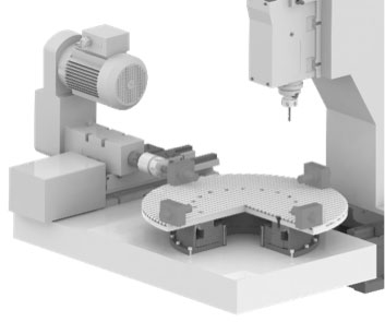
Many rotary index table end users need the flexibility afforded by having a fully programmable tool. A seemingly simple way to achieve this is by using a gear head coupled to a servo motor or an AC motor with an encoder. In reality though, while this seems simple and cost-effective, because of the physics described above, high inertia, combined with a goal of high accuracy can create a problematic mis-match.
With a servo-driven barrel cam rotary index table, it’s possible to deliver a wide range of table sizes, with zero backlash and unparalleled accuracy. Servo driven rotary indexers allow heavy inertial loads to be rotated in a very smooth and controlled manner.
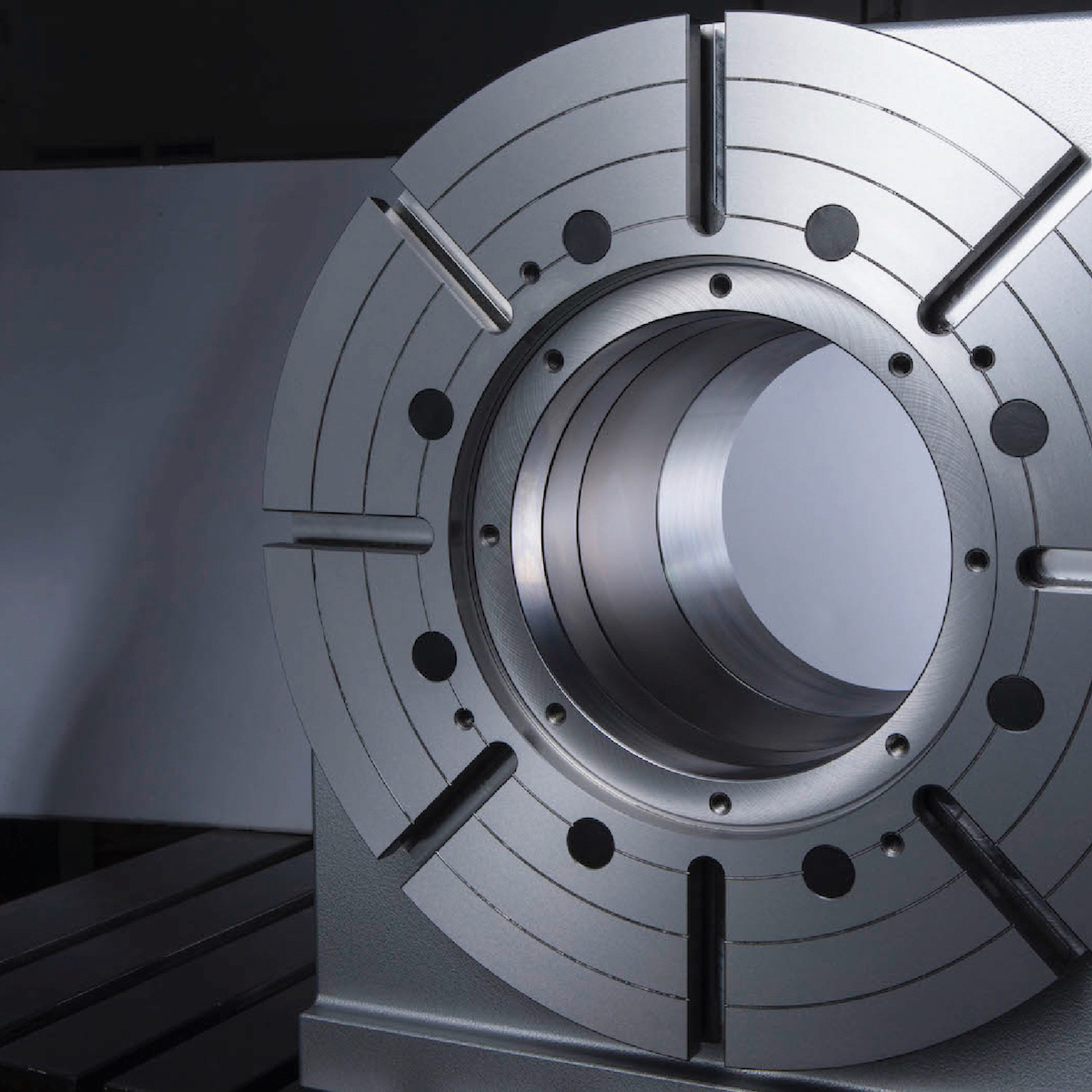
Cam-driven rotary index tables can have significant advantages over other types of rotary index table drive systems such as gear drives. Cam-driven rotary index tables provide extremely high accuracy because they operate with no backlash. There are several types of commonly used cam-driven rotary index table systems, each is best for a specific application.
Barrel cams represent strength in indexing. Primarily found in rotary index tables, indexers utilizing barrel cams feature the greatest strength/size offering available.
Cam driven rotary table indexers are sometimes call "fixed indexers". With a fixed indexer, the cam drives receive constant power input from the motor. This rotates the cam which then rotates the output. Based upon the design of the drive, the output will have "dwell" periods (when the output is stopped) as well as acceleration, deceleration and peak velocity. Cam-driven rotary index tables have a number of advantages, however, they won"t meet the needs of every application.
Rotary index tables can also be "flexible". Flexible rotary index tables use a cam that has a constant lead, that is the output is at a constant velocity if the motor is running at a constant velocity. Constant lead cams provide a high-precision mechanical transition of power to the output and since acceleration and deceleration are still necessary, the logic controller for the index tables motor provides the necessary control.
Rotary indexing table use is widespread in automated assembly machinery and selecting the proper mechanism is essential for both maximizing performance and minimizing the cost of this critical component. This how-to-guide will explore two common devices that can be used for rotary indexing and give advice for proper selection. These two popular devices are cam indexing drives and servo rotary tables.
Cam indexers are a ubiquitous mechanism that have been used for rotary tables for many decades. They are a great fit for applications that will always index the same angle and that require high-precision positioning at a very reasonable cost. A cam indexer uses a mechanical cam to provide the motion control to position the load. A mathematical motion curve is machined onto the cam that provides extremely smooth and repeatable motion.
A cam indexer has two main modes of operation. One mode is referred to as “Cycle-on-Demand”. This indicates that the camshaft will be cycled one revolution at a time to advance the output one position at a time. This is typically achieved by using an inexpensive camshaft sensor package to detect camshaft position and a VFD to stop and start the motor. The camshaft dwell period offers a wide window for the camshaft to stop without affecting the position of the output. To cycle the indexer, a PLC gives a command to the VFD to accelerate the drive motor to a preset speed, the cam rotates one revolution indexing the output, a sensor sends an in-position signal to the PLC, and the PLC signals the VFD to stop the camshaft during the cam dwell position. The table will be in the dwell position for however long is necessary to complete the work at each station. The dwell time can range from a fraction of a second to several minutes or hours depending on the application. This combination allows very accurate positioning with an inexpensive drive system.
A fully programmable servo rotary table is another common option. There are two specific cases where a servo rotary table is advantageous. The first is when a flexible motion pattern is required. An example is two different products being run on one machine that each require different indexing patterns. The other situation that suits a servo indexer is when extremely fast positioning is required followed by a long dwell period. A cycle-on-demand cam indexer is limited by the need to accelerate the camshaft up to speed during the dwell period before output motion is started. There are practical limitations to how fast the camshaft can be accelerated so there will be a delay before motion is started. With a servo rotary table, the output rotates as soon as the servomotor starts moving. A practical example would be a load being indexed 90 degrees in 0.25 seconds. This is not difficult for a continuous cam indexer or a zero-backlash servo indexer, but a cycle-on-demand cam indexer may struggle with that motion. For quick servo indexing applications, a preloaded gear reducer with zero-backlash is critical to achieving smooth indexing motions with minimal settling time. A zero-backlash RollerDrive mechanism would be an optimal choice to achieve accurate positioning with great dynamic response.
For either style of indexer, application information including moment of inertia, indexing angle, indexing time, and dwell time is required. A reputable manufacture should then be able to properly size the rotary table for the application.

ATS Systems is a national leading machine tool accessories and automation supplier delivering reliable solutions with unwavering support that increases manufacturing productivity and throughput leading to profitable results for its customers. For over 20 years, ATS has installed over 135K machine tool accessories and automation systems allowing customers to achieve productivity gains of over 50% and increasing profitability.
Whether your CNC control has AC or DC drives, uses Fanuc, Mitsubishi, Yaskawa, Glentek, Siemens, Baldor, etc. we can build your rotary table with a compatible motor for just about any 4th axis-ready machine on the market! If you need help getting a machine 4th axis ready, we also supply the parts you need; such as amplifiers, drives, cables and connectors. If your application does not require simultaneous 4th axis cutting, we offer an easy-to-program, single-axis control box that can be M-function interfaced to your CNC machine. The control box can either be programmed directly or fed data via RS-232 for fast, accurate indexing to any angle.


 8613371530291