
homemade rotary table in stock

Years ago, before I learned CNC, I owned a Phase II 8″ horizontal/vertical rotary table that I purchased from Kap Pullen’s Getmachinetools.com store. He has them at a good price, BTW, and he’s a darned nice fellow to deal with as well as being a frequent HSM contributor. Anyway, its a nice little table, but I hadn’t done a whole lot with it for quite a while after purchasing it. As is so often the case, one day, a project landed on my doorstep and I was glad to have it.
Before I could get started, however, I had to make some accessories for it. Basically, I needed some T-Nuts to fit the table, as well as a little fixture that makes it easy to hold a plate up off the table through a hole in the center so you can machine it. The latter, what I call a “plate machining fixture”, was inspired by something similar I saw the Widgitmaster of CNCZone fame using to make Dremel clamps for his mini-router:
The Plate Maching Fixture and 3 Homemade T-Nuts. T-Nuts are easy to make: square a block to the proper dimensions, mill the side reliefs, drill, and tap. These are much smaller than the mill’s Bridgeport standard T-slots, so I made them myself and I’m using 1/4-20 bolts with them. They’re made of mild steel.
I turned the round spigot using the 4-jaw on the lathe. I’m making the fixture out of MIC-6 aluminum plate, which is pre-ground very flat on the sides. This is a 5 inch by 3 inch piece. I’ve clamped it to the rotab using my T-nuts and the regular mill clamps and step blocks. It is sitting on parallels to make sure I don’t cut into the table. You can also see how I’ve clamped the rotary table to the mill table using a big cast iron V-block I have. You can never have to many blocks with precision faces hanging around!
Having a 4-jaw chuck on your rotary table is mighty handy! Because it’s a 4-jaw, you can dial in the workpiece by adjusting the jaws until it is perfectly concentric with the table’s axis of rotation. The best way is to make an adapter plate that attaches to the back of the chuck in the same way that your lathe does so you can exchange lathe tooling with the rotab. Here is an example:
For the example, the chuck is threaded onto the adaptor plate, and then the holes in the adapter plate’s flange are used to bolt down to T-nuts on the table.
In my case, I bought a 4-jaw from Shars brand new, and simply drilled some through-holes in the chuck to mount to the table directly without an adapter plate:
First, you want to make sure your part is properly centered on the table. To do that, I clamp the table down on the mill table (no special place is needed), put my Indicol indicator holder on the mill spindle, and find some round feature on the part to indicate on. For example, on the plate milling fixture above, indicate on the round boss, or on the center hole. Spin the table and bump the part in until spinning the table doesn’t move the indicator.
Second, locate the center of rotation directly under the mill spindle. You can simply use the X and Y table handwheels to do this. Use that Indicol to indicate off of a circular feature you want centered under the spindle. Turn the indicol around on the spindle and adjust the handwheels until the indicator stays put relative to the spindle position. A Blake Coaxial indicator will make this last even simpler.
When you’re rounding partially by cranking a part around on the rotary table, it’s really easy to go a little too far and screw things up. The answer is to drill the end points to make the exact stopping point on the rotab a lot less sensitive:
Centering with a Blake indicator is really fast, but what if you don’t have a Blake, or worse, what if your mill is too small to accomodate one? Here is a nice solution I found on a German site. This fellow has made an ER collect fixture for his rotary table, and has taken care that when installed on the table, the axis of the collet is aligned with the table’s axis. He can then place a dowel or other straight pin in the collet and line up until it will go into a similarly sized collet on the spindle. Nice trick! It’s similar to how Widgitmaster showed me to align a drill chuck on a QCTP to the lathe centerline with a dowel pin held in the lathe chuck.
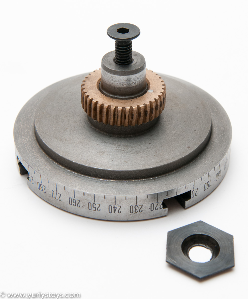
I guess I should explain how the dividing works. As you may have noticed there is no degree scale. Well you don"t need one and you don"t need trig tables. You will need a calculator.
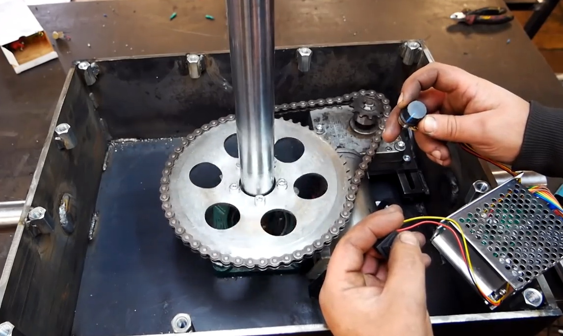
There isn"t much to explain how it goes together- the pictures say it all. The coupling between the stepper and rotary table should be accurately bored. The one in the picture was my 3rd attempt and finally done on a metal lathe. Even there I have tiny wiggle from eccentricity but my hoedown is very accommodating. Don"t get panicky over the small size stepper. There is a 72/1 ration between the stepper and the table creating lots of torque.
The tail stock is an original. Using the shelf brackets was because I owned them. It works fine and gives me lots of adjustment. The screw in the tail stock is also a 1/2 threaded rod already in the shop. Grind a 90deg point and then use your 90deg router bit to indent the stock. It"s very important to make sure the screw point is at the exact height as the ctr of the rotary table.
The picture of the disk shows a way of connecting stock to the rotary. The 4 bolts are 3/8 and the threaded part just fits the slots on the rotary. By putting them carefully on a circle and 90deg apart you have a great attachment system for the headstock. If you look carefully you will see one of my bolts needed trimming due to poor fit.

You don’t always need a rotary welding table, but when you do there is nothing like it to make welding all around a part easier or cleaner. You can buy them for a lot of money or a little, but the quality of the cheaper ones is always something you question. So what a lot of folks do is build their own. This build here is pretty cool, and different than some, and makes for a rotary welding table that can spin whatever you want to lay some killer tig welds on. It’s made from an old faceplate, some scrap steel plate and angle iron, an old propane tank, some bearings and some electric bits. The way it has been thought out and put together is cool and inspiring for building one yourself. If you follow along you can build this yourself, or just use it as a roadmap for building one that is custom to what you need and to work with the parts you have.
This thing has some great features, is WAY more adaptable than most of the others I’ve seen, and I can see where it would really come in handy when working on certain welding projects.
I like seeing stuff getting put together like this that uses both new parts and scrap stuff, because it is relatable and inspires people to look through their own pile of parts when they need a new custom tool for the shop.


 8613371530291