
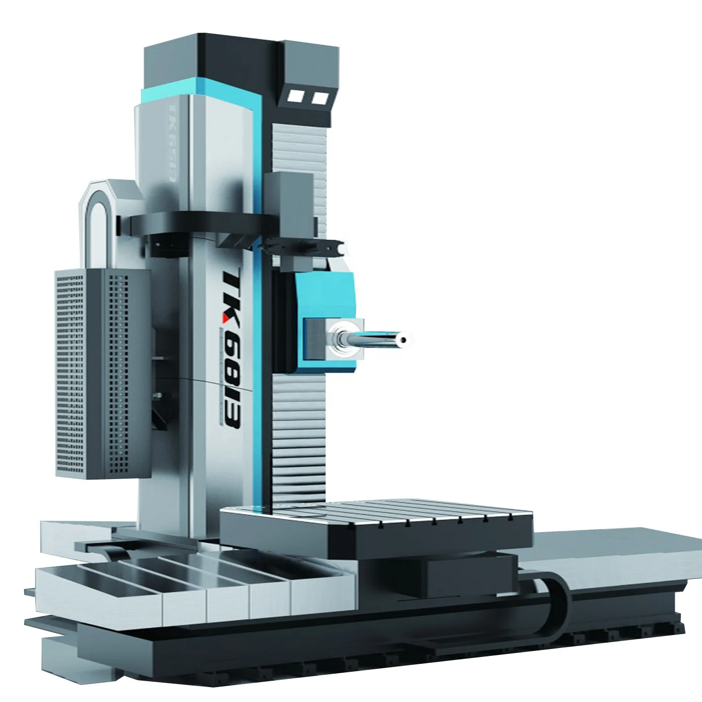
horizontal boring mill with rotary table free sample

MAKE : INFRATIREA Rotary Table MODEL : 1700mm x 2000mm with 3m traverse - 20tons capacity Specification : Table surface mm x mm 1700 x 2000 T-slots 28H8 Longitudinal travel mm 3000 Max. load on table kg 15000 Dimensions [Lxlxh] mm 6260 x 2000 x 920 Aprox. weight kg 16000
Nomura Model B-85BT-2 Horizontal Boring Mill Table Type.3.35" Spindle Dia. 40" Vert, 20" spdl Travel, 40" Cross Travel, Rapid Traverse, 35.5" x 39" Rotary T Slot Table, Pendant Control, DRO
Reversible clamp, 4th axis, rotary table, rotary dividing table, controlled rotary table, dividing attachment, dividing head, rotary indexing table rotary coupling

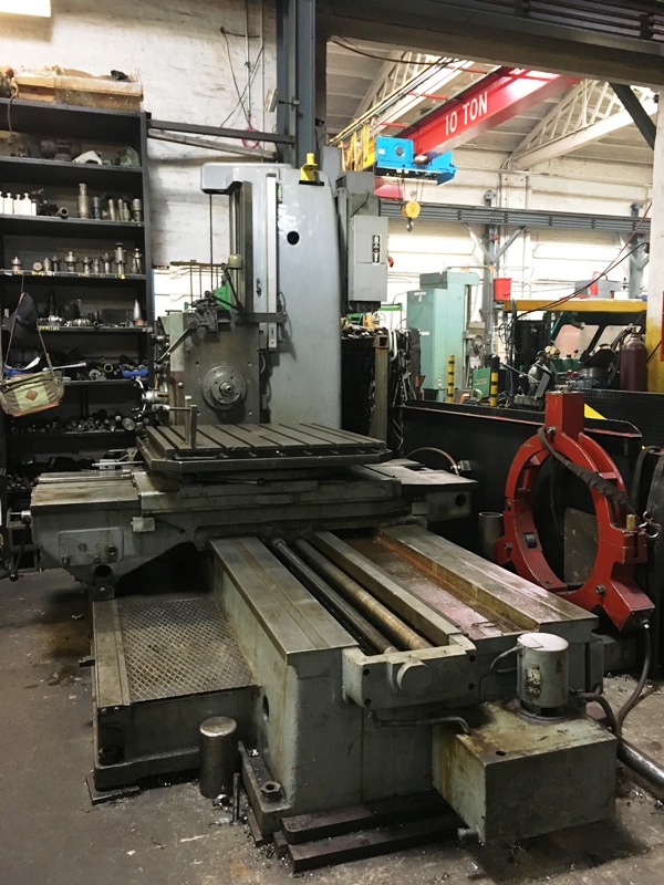
“Huge.” That’s probably the first word that springs to mind when thinking of horizontal boring mills (HBMs). At their largest, the massive machine tools can have a work envelope with a length of more than 50 " (15.24m), dominating a huge chunk of floor space. However, gigantic floor-type HBMs aren’t the only option. Smaller ones with rotary tables add versatility to a shop while using considerably less floor space than their bulkier brethren.
“The smallest one we offer is a table-type machine with a footprint of 3m × 3m (9.84 "×9.84 "), with a travel of about 1.2m (3.94 "),” said Joe Vidmar, service manager for machine tool builder Toshiba Machine Co. Canada Ltd., Markham, Ontario. “A lot of our customers are job shops, and whatever comes through their doors goes on a boring mill at some point in the manufacturing process.”
A horizontal boring mill, despite the name, is capable of more than just boring. According to Bob Connors, vice president of sales and marketing for United Precision Services, a Cincinnati-based distributor of Union machine tools, a range of HBMs are available, including table, planer and floor types.
Table-type models typically include a rotary table. A compound slide is used to move the rotary table in the X and Z axes. Once X-axis travel needs exceed 100 " (2.54m), Union moves to a planer-type design, which has a full bed under the X-axis.
“With planer-type machines, if you’ve got 10 " of X travel, you’ve got a bed that’s 10 " long to support the table as it moves,” Connors explained. “To achieve Z-axis movement, planer-types move the column rather than the table. That’s a more robust design, because you don’t have the compound slide, which is limiting.”
On a traditional table-type HBM, the saddle—and hence travel—is usually limited to the size of the bed. By eschewing the rotary table, planer designs typically travel about 4m (13.12 "). Beyond that, floor-type designs use a moving column for all axial travel.
Because of the nature of the design, all small horizontal boring mills are table-type, Connors noted, because the limitations of the table are outweighed by the flexibility it offers when machining small parts. This flexibility allows a table-type HBM to function like a horizontal machining center.
“If you look at HMCs, you’ll see a standard 630mm pallet, then an 800mm pallet, then a 1,000mm pallet,” he said. “Our boring mills pick up where the HMC leaves off. Applications would be similar—typically prismatic parts—but boring mills are outfitted with an integrated rotary table, similar to an HMC, which gives you access to four sides of the part.”
Toshiba offers a full range of table-type boring mills for various applications, including the BTH-110.R18, developed to provide machining center flexibility, according to the company.
Many United customers run machining center-style parts on an HBM because of its larger work envelope, he continued, although the unique capability of an HBM is the W-axis—an extendable quill, or spindle bar. The quill diameter determines the size of the work envelope, with the smallest machine United sells being the Union T-110, which has a 110mm (4.331 ") spindle bar. The machine’s work envelope is 80 "×63 "×60 " (2.032m × 1.600m × 1.524m), with 22 " (0.559m) of Z-axis spindle travel.
“On the 110mm boring mill, the quill extends up to 0.5m and not much more, because performance decreases drastically past that point,” he explained. “The larger the quill diameter, the longer it can extend, but also the more chance of it causing interference from the extra bulk.”
The advantage of a quill is that it gives a machine more reach by bringing the tool closer to the part without relying on tool extenders, Vidmar continued. On an HBM, it is easy for the tool to reach whatever workpiece faces are closest to the edge of the rotary table, but it can be hard to access features closer to the table’s center. “The quill gives up a little bit of rigidity in the tool, but you gain flexibility in terms of the parts you can make,” he said.
That flexibility allows job shops like Superior Machining Ltd., Concord, Ontario, to perform a range of work on one machine. Superior has several HBMs, including a Toshiba BTD-200QF table-type mill, which has a 1m × 1m (3.28 "×3.28 ") rotary table. The shop uses the mill to drill, tap, high-feed mill, endmill and, of course, bore, according to President Dan Boaretto.
“The smaller machine is extremely useful because you can reach the center of the table quite easily,” he explained. “If you put a small part on one of our larger tables, it becomes very difficult to reach some of the features—the table size will actually interfere with the Z-axis movement.”
A smaller rotary table, Boaretto continued, allows a part to be placed on the table and reached on all sides, while the quill allows the tool to reach internal faces by extending the W-axis. “You can stack up tooling on a machining center, but when you have a quill, that’s about as rigid as you can get for those applications. It’s just a solid bar that lets you reach farther from your spindle face.”
Pretty much anything that will fit on the table can be machined, Toshiba Machine’s Vidmar said. “Mold shops are a great example,” he said. “They will use a boring mill to rough mold cavities, complete side work, like mounting holes and waterlines, and drill, tap and square up the mold. Virtually everything but high-speed finishing operations can be done on a boring mill.”
Granted, a vertical machining center might technically be able to perform more tasks in a smaller footprint than a table-type HBM, but machining large parts on a VMC presents issues, according to Dale Hedberg, Feeler product manager for Methods Machine Tools Inc., Sudbury, Mass.
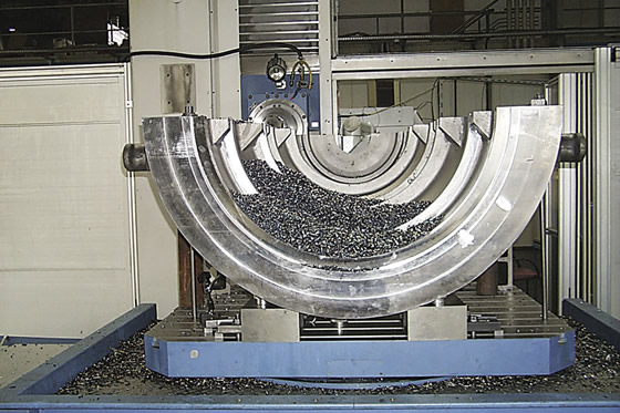
“Methods’ Feeler boring mills feature ultrahigh precision when machining large workpieces, and 4-axis capability for work on multiple part surfaces,” he said. “You can probably machine all four sides in one setup by rotating the part to one side and machining the front and back faces. It’s a very efficient way to machine a part.” In addition, a substantial quill diameter and table capability for boring operations enables reaching into areas which are not accessible with typical spindles, allowing the machines to work with large, awkward workpieces.
Hedberg added that HBMs are typically more effective than VMCs when boring and drilling, as chip evacuation is more efficient with an HBM because it is not working against gravity to pull chips out of the cut.
“A table-type boring mill gives you a smaller footprint and a little more accuracy versus floor-type HBMs, but the work envelope is limited by the table size,” he explained. “However, you have the ability to do deep boring and drilling.”
“The name, of course, indicates boring,” said United’s Connors. “They can do much more than that, but they excel at a process called line boring, which involves machining two bores in perfect parallelism. In years past, and sometimes today, this was typically done on a HBM with a line bar that had a cutter on it and moved along the Z-axis.”
This operation aligns bores spaced a long distance apart, he explained, such as in a gearbox. While Connors has seen many shops bore one side on a machining center, then use an index table to line up the other side, index tables are still not completely exact, as each time an axis moves, inaccuracies are added.
“Granted, there are a lot of difficulties with line boring,” he admitted. “For example, when you’re extending the bar that far, gravity will take its toll and you have to support the end of the bar against its own weight. But sometimes you might have a journal in the center of a part—a gearbox is a good example again—and the difference between a machining center and a boring mill is that a boring mill will provide reach and rigidity to make sure everything is perfectly aligned.”
“Several manufacturers are doing wellhead parts, flanges, manifolds and fluid ends, and a very popular HBM attachment for those jobs is the U-drill,” Hedberg said, noting the specialized drill head makes repeated axial cuts. “With a U-drill, you automatically adjust the quill length, which forms different cutting radii in the workpiece. Cutting the desired radius is fully adjustable through the CNC program and allows you to perform machining operations in ways most standard machining centers can’t really manage.”
Regarding options, table-type HBMs typically come standard with an automatic toolchanger and, obviously, a rotary table, but machine customization is virtually limitless.
“Automatic spindle probes and tool probes are common options, and pallet changers are not standard but are available and fairly common in production applications,” said United’s Connors. “Almost any automation capability that exists for a machining center can be applied to a horizontal boring mill.”
According to Boaretto, Superior was drawn to Toshiba Machine’s reputation for heavy-duty, dependable tools, and the ability to outfit its BTD-200QF table-type HBM with certain options.
“It’s got an automatic toolchanger, like most modern machines, but we also have some options on the control that help to reduce cycle times, like a high-feed machining option, Archimedes interpolation and a Shape function, which allows us to program a little more easily if we’re milling complex surfaces,” he said. “If you’re doing heavy work with difficult-to-cut materials, you aren’t going to be flying through the material, but those options do help increase productivity.” CTE

VEVOR is a leading brand that specializes in equipment and tools. Along with thousands of motivated employees, VEVOR is dedicated to providing our customers with tough equipment & tools at incredibly low prices. Today, VEVOR has occupied markets of more than 200 countries with 10 million plus global members.
VEVOR is a leading brand that specializes in equipment and tools. Along with thousands of motivated employees, VEVOR is dedicated to providing our customers with tough equipment & tools at incredibly low prices. Today, VEVOR has occupied markets of more than 200 countries with 10 million plus global members.
The mill rotary table is one of the main accessories of milling machine. As a precision work positioning device, it is widely used for indexing drilling, milling, circumferential cutting, boring, etc. The rotary turn table for milling machine is made from HT200 casting with high quality. It has already passed the ISO9001 quality system certification. They are are very popular on the market for their superior performance, excellent design and reasonable cost.
Both vertical and horizontal with two functions. Circle cutting, indexing drilling, milling and more complicated work are possible when the vertical position of the table is used together with the tail part.
VEVOR is a leading brand that specializes in equipment and tools. Along with thousands of motivated employees, VEVOR is dedicated to providing our customers with tough equipment & tools at incredibly low prices. Today, VEVOR has occupied markets of more than 200 countries with 10 million plus global members.
VEVOR is a leading brand that specializes in equipment and tools. Along with thousands of motivated employees, VEVOR is dedicated to providing our customers with tough equipment & tools at incredibly low prices. Today, VEVOR has occupied markets of more than 200 countries with 10 million plus global members.
The mill rotary table is one of the main accessories of milling machine. As a precision work positioning device, it is widely used for indexing drilling, milling, circumferential cutting, boring, etc. The rotary turn table for milling machine is made from casting with high quality, can work with a set of dividing plate.
Both vertical and horizontal with two functions. Circle cutting, indexing drilling, milling and more complicated work are possible when the vertical position of the table is used together with the tail part.
Three dividing plate set(Plate "A" - 15, 16, 17, 18, 19, 20 Plate "B" - 21, 23, 27, 29, 31, 33 Plate "C" - 37, 39, 41, 43, 47, 49). A set of wrench and screws are free for you with your installation.
Our dealer and auctioneer members offer the most extensive selection of used machinery in the world, with thousands of machines available in warehouses and plants across the globe.
Years ago, before I learned CNC, I owned a Phase II 8″ horizontal/vertical rotary table that I purchased from Kap Pullen’s Getmachinetools.com store. He has them at a good price, BTW, and he’s a darned nice fellow to deal with as well as being a frequent HSM contributor. Anyway, its a nice little table, but I hadn’t done a whole lot with it for quite a while after purchasing it. As is so often the case, one day, a project landed on my doorstep and I was glad to have it.
Before I could get started, however, I had to make some accessories for it. Basically, I needed some T-Nuts to fit the table, as well as a little fixture that makes it easy to hold a plate up off the table through a hole in the center so you can machine it. The latter, what I call a “plate machining fixture”, was inspired by something similar I saw the Widgitmaster of CNCZone fame using to make Dremel clamps for his mini-router:
The Plate Maching Fixture and 3 Homemade T-Nuts. T-Nuts are easy to make: square a block to the proper dimensions, mill the side reliefs, drill, and tap. These are much smaller than the mill’s Bridgeport standard T-slots, so I made them myself and I’m using 1/4-20 bolts with them. They’re made of mild steel.
I turned the round spigot using the 4-jaw on the lathe. I’m making the fixture out of MIC-6 aluminum plate, which is pre-ground very flat on the sides. This is a 5 inch by 3 inch piece. I’ve clamped it to the rotab using my T-nuts and the regular mill clamps and step blocks. It is sitting on parallels to make sure I don’t cut into the table. You can also see how I’ve clamped the rotary table to the mill table using a big cast iron V-block I have. You can never have to many blocks with precision faces hanging around!
Having a 4-jaw chuck on your rotary table is mighty handy! Because it’s a 4-jaw, you can dial in the workpiece by adjusting the jaws until it is perfectly concentric with the table’s axis of rotation. The best way is to make an adapter plate that attaches to the back of the chuck in the same way that your lathe does so you can exchange lathe tooling with the rotab. Here is an example:
For the example, the chuck is threaded onto the adaptor plate, and then the holes in the adapter plate’s flange are used to bolt down to T-nuts on the table.
In my case, I bought a 4-jaw from Shars brand new, and simply drilled some through-holes in the chuck to mount to the table directly without an adapter plate:
First, you want to make sure your part is properly centered on the table. To do that, I clamp the table down on the mill table (no special place is needed), put my Indicol indicator holder on the mill spindle, and find some round feature on the part to indicate on. For example, on the plate milling fixture above, indicate on the round boss, or on the center hole. Spin the table and bump the part in until spinning the table doesn’t move the indicator.
Second, locate the center of rotation directly under the mill spindle. You can simply use the X and Y table handwheels to do this. Use that Indicol to indicate off of a circular feature you want centered under the spindle. Turn the indicol around on the spindle and adjust the handwheels until the indicator stays put relative to the spindle position. A Blake Coaxial indicator will make this last even simpler.
When you’re rounding partially by cranking a part around on the rotary table, it’s really easy to go a little too far and screw things up. The answer is to drill the end points to make the exact stopping point on the rotab a lot less sensitive:
Centering with a Blake indicator is really fast, but what if you don’t have a Blake, or worse, what if your mill is too small to accomodate one? Here is a nice solution I found on a German site. This fellow has made an ER collect fixture for his rotary table, and has taken care that when installed on the table, the axis of the collet is aligned with the table’s axis. He can then place a dowel or other straight pin in the collet and line up until it will go into a similarly sized collet on the spindle. Nice trick! It’s similar to how Widgitmaster showed me to align a drill chuck on a QCTP to the lathe centerline with a dowel pin held in the lathe chuck.

A rotary table is a precision work positioning device used in metalworking. It enables the operator to drill or cut work at exact intervals around a fixed (usually horizontal or vertical) axis. Some rotary tables allow the use of index plates for indexing operations, and some can also be fitted with dividing plates that enable regular work positioning at divisions for which indexing plates are not available. A rotary fixture used in this fashion is more appropriately called a dividing head (indexing head).
The table shown is a manually operated type. Powered tables under the control of CNC machines are now available, and provide a fourth axis to CNC milling machines. Rotary tables are made with a solid base, which has provision for clamping onto another table or fixture. The actual table is a precision-machined disc to which the work piece is clamped (T slots are generally provided for this purpose). This disc can rotate freely, for indexing, or under the control of a worm (handwheel), with the worm wheel portion being made part of the actual table. High precision tables are driven by backlash compensating duplex worms.
The ratio between worm and table is generally 40:1, 72:1 or 90:1 but may be any ratio that can be easily divided exactly into 360°. This is for ease of use when indexing plates are available. A graduated dial and, often, a vernier scale enable the operator to position the table, and thus the work affixed to it with great accuracy.
Rotary tables are most commonly mounted "flat", with the table rotating around a vertical axis, in the same plane as the cutter of a vertical milling machine. An alternate setup is to mount the rotary table on its end (or mount it "flat" on a 90° angle plate), so that it rotates about a horizontal axis. In this configuration a tailstock can also be used, thus holding the workpiece "between centers."
With the table mounted on a secondary table, the workpiece is accurately centered on the rotary table"s axis, which in turn is centered on the cutting tool"s axis. All three axes are thus coaxial. From this point, the secondary table can be offset in either the X or Y direction to set the cutter the desired distance from the workpiece"s center. This allows concentric machining operations on the workpiece. Placing the workpiece eccentrically a set distance from the center permits more complex curves to be cut. As with other setups on a vertical mill, the milling operation can be either drilling a series of concentric, and possibly equidistant holes, or face or end milling either circular or semicircular shapes and contours.
To create large-diameter holes, via milling in a circular toolpath, on small milling machines that don"t have the power to drive large twist drills (>0.500"/>13 mm)
with the addition of a compound table on top of the rotary table, the user can move the center of rotation to anywhere on the part being cut. This enables an arc to be cut at any place on the part.
Additionally, if converted to stepper motor operation, with a CNC milling machine and a tailstock, a rotary table allows many parts to be made on a mill that otherwise would require a lathe.
Rotary tables have many applications, including being used in the manufacture and inspection process of important elements in aerospace, automation and scientific industries. The use of rotary tables stretches as far as the film and animation industry, being used to obtain accuracy and precision in filming and photography.

Horizontal Mills – The horizontal mills can perform a number of applications in one setup, and their configuration allows for machining large parts. The arrangement of the horizontal boring mill allows for easy access and placement of the workpiece on the machine table. Large workpieces can be placed on the machine table with an overhead crane and can overhang the table if needed. The arrangement also allows for easy chip removal from the machining operation.
We run five horizontal mills out of our shop. The largest of our horizontal mills has an operating window of 157″ in X and 92″ in Y. An auxiliary rotary table can be added to the mill for 4th axis milling, while a part is being rotated. This adaptation is used for machining parts such as fluted rolls and internal helical grooves inside bushings. Two of our horizontal mills have rotary tables, which allows for machining on different sides of the part in one setup.

ROTARY TABLE, PARTICULARLY FOR MACHINE TOOLS Filed June 21, 1954 R. BELLMANN Oct. 8, 1957 4 Sheets-Sheet 1 INVENTOR REINHOLD BELLHRNN BY ROTARY TABLE, PARTICULARLY FOR MACHINE TOOLS Filed June 21, 1954 R. BELLMANN 4 Sheets-Sheet 2 931E. -33: a a $5. a
ROTARY TABLE, PARTICULARLY FOR MACHINE TOOLS v Filed June 21, 1954 4 4 Sheets-Sheet s INVENTOR i 1 EEKJJLVLKIIW ATTORNEY 4 Sheets-Sheet"4 R. BELLMANN INVENTOR REIggOLD Ball??? BY V "Mwa ATTORNEY ROTARY TABLE, PARTICULARLY FOR MACHINE TOOLS Filed June 21, 1954 ROTARY TABLE, PARTICULARLY FOR MACHINE TOOLS Reinhold Belimann, Le Locle, Switzerland, assignor to Dixi S. A., Le Lo"cle, Switzerland Application June 21, 1954, Serial No. 438,227 Claims priority, application Switzerland July 2, 1953 Claims. (Cl. 74824) This invention relates to a rotary table which can alternately be clamped, released and finely adjusted and which is particularly used in machine tools such as, for instance, horizontal boring and milling machines, dividing or indexing machines and the like. 7
Prior rotary tables of that kind comprise separate control means for clamping and releasing the table and for the fine adjusting device, one of these control means, such as a lever or"the-like, serves for clamping and releasing, 1 and the other control means, for instance, for swinging a worm of the fine adjusting device into and out of engagement. These prior solutions are uncomfortable in manipulation and injurious to accuracy. I
The above-mentioned and other inconveniences are done away with by the invention in that the rotary table according to the invention has only one control means,
the fine adjusting device. Due to the invention it is also possible to clamp the rotary table exclusively by springs so thatno force components in the rotary plane of the table occur. Moreover, .due .to the. springsthe clamping pressure is uniformly distributed.
The rotary table according to the invention may for instance be used in a machine as a rotary machine table and/ or as a top or set up table or the like.
Fig. 1 is a perspective view of some parts of a hori zontal precision boring and milling machine, and of an auxiliary table attachment temporarily mounted on the rotary machine table.
Fig. 2 is a vertical section of the auxiliary attachment through the rotary axis of its rotary table. 7 Fig. 3 illustrates an antifriction bearing and a control surface cooperating with the bearing, these means belonging to a mechanism controlling the clamping de vice for the rotary table of the auxiliary attachment.
atent O riage 3. Besides the adjustment means 10, 11 an optical means (not shown) may be provided for adjusting the angular position of the rotary machine table 7, such as for instance a. precision rule which may be read by means of a microscope or projected onto an image screen. Control lever 12 pivoted on the carriage 3 serves for: clamping fast the table 7 after angular adjustment of the latter. The tool 15 is fixed to the rotary hollow spindle 14 which is journalled on the drill head 13 of the machine and surrounds the axially adjustable drill spindle (not shown). The above-described parts of a horizontal boring and milling machine and their structural arrangement and interrelation are well known to those skilled in the art and, therefore, need no further detailed description and illustration.
An auxiliary set up or top attachment 16 is provided to be temporarily clamped to the rotary machine table 7 either in an upright or vertical position or in a hori-: zontal position. The auxiliary attachment is designed in accordance with applicants copending patent applica tion of even date, Serial Number 438,226, bearing the title Top table with a rotary plate, particularly for use in machine tools. The attachment 16 has a casing 17 of rectangular shape in plan view, and a circular rotary table 18 journalled on the casing 17 and provided with clamping grooves 19 and an outer circular graduation or division 20 cooperating with a mark 21 of the casing 17 for coarse hand adjustment of the angular position of the rotary table 18.
. v Thecasing 17 has laterally open slots 25 to receive clamping or holding-down bolts 26 held in a well-known manner in the grooves 8 of the machine table 7, the attac hment 16 being clamped by the bolts 26 to the machine table 7 in the position desired for the operation or operaf tions to be done.
In order to obtain a suitable rotary mounting of the table 18 on the attachment casing 17 a bearing or collar 37 integral with the plate 27 extends from the latter through the hollow space 35 down to the level of the front face 22 of the casing 17. A turning pin 40 is journalled in the bearing 37 and is held in axial direction by means of a disc 38 and a .bolt 39. The rotary table 18- is fixedly secured to the turning pin 4 In order that the table 18 may also be useful for precision work, the following provisions are taken to I satisfactorily clamp the rotary table 18 after its adjustcontrolling the fine adjustment drive for the rotary. table ment to the desired angular position, that is, to provide for the clamping effect withstanding all the forces applied to the workpiece during machining and to avoid any change of the adjusted angular position of the top table by the clamping operation.
For that purpose, clamping bolts 41 (e. g. two, three" or more bolts) distributed on an imaginary circle around the pin 40 are guided for axial movement in sleeves 42 of the casing plate 27 and are parallel to the axis ofrotation of the table 18 (Figs. 2 and 5). The bolts 41 comprise shoes 43 lying above a flange 44 of a ring 45 fixed to the rotary table 18. An adjustable compression spring 47 of for instance about 500 kilograms elastic forceis inserted between the flange of each sleeve 42 and an adjusting nut 46 of the respective bolt 41 and" presses the bolt 41 in the direction towards a lever 48. pivoted on the casing 17 as at 49. The lever 48 of each" bolt 41 is disposed in such a way that it transmits its force to the bolt 41 only in the axial direction ofthe latter. The free end of each pivoted lever 48 carries I an antifriction bearing 59 (see also Fig. 3) engaging a rotary control disc 51 coaxial to the rotary table 18. The control disc 51 comprises depressions 52 and even" surface portions 53 lying at a higher level than the de;
A circular scale I pressions 52. The control disc 51 is rotatably supported by means of antifriction bodies 54 such as rolls or balls running on a thrust plate 55 fixed to the bearing 37, and is linked by means of a rod 58 and an intermediate lever 59 to a control lever 57 accessible from the outside and pivoted on the casing 17 as at 56. If the control disc 51 is turned around the rotary axis of the table 18 by means of the control lever 57 so that the antifriction bearings 50 engage the depressions 52, the pivoted levers 48 are in their lowermost position and the shoes 43 are pressed only by their springs 47- against the inner front face of the flange 44 and clamp the rotary table 18 fast in its adjusted angular position. In this clamped position the bolts 41 do not contact their levers 48, Since the springs 47 exert only forces vertical to the rotary plane of the table 18 and since there is no positive connection be: tween the bolts 41 and their control means, clamping the rotary table 1 8 is obtainedwithout any force component in the rotary plane of the table 18,"wh ich could change the position of the plate by a small; amount during the clamping operation. Since clamping is only effected by means of springs 47, the clamping "pressure is also uniformly distributed on all bolts 41 The levers "48 merely serve for releasing the rotary table 18. The antifriction bodies 54 and bearing 50 considerably facilitate the operation of. the clamping device relatively to the well-known constructions comprising eccentrics, threade ing, worm gears etc.
For increasing the indexing or dividing accuracy and for maintaining the same over a long period, the attachment 16 with the table 18 is provided with an optical indexing or dividing attachment comprising an innera n nular. precision rule 60 fixed to the rotary"table 18 and:
readable from the outside by means of a microscope 61 (Figs. 1 and 2). In another performance means"may be provided for projecting the rule 60 onto an image screen. For turning the rotary table 18 on anfoptical j fine adjusting operation, the following simple device is provided (Figs. 2 and S): The shaft of the fine adjusting handwheel 62 (Figs. 1 and rotatably mounted on. the casing 17 carries a worm 63 engaging a worm wheel 64 keyed on a sleeve 66 loosely rotatable about a bolt 65 whose axis is parallel to the rotary axis of the table 18 (Figs. 2 and 5). A gear wheel 67" looselyarranged.
on the bolt 65 is permanently in mesh with a gear wheel 69 rigidly fixed to the hub 68 of therotary table 18. The axially adjustable bolt65 is under the influence of: a compression spring 70 of, e. g. about 5 kilograms elastical force, which may be adjusted by means of a nut 71- ofthe bolt 65. In Fig. 2, the bolt 65 under the constraint of the spring 76 bears againsta lobe 72 of" a radially projecting lug 73- of the control 511 so that thebolt 65 is in "liftedposition and the gear wheel.
67, on. a coarse hand adjustment of" th"e rotary "table 18, turns idly with the gear wheel-69, while the worm wheel 64 is at rest. When the control lever 57" is moved to the fine adjusting position it turns the controljdisc 51 in sucha direction that the lobe 72" comes out of reach of the bolt 65 and the spring 76 pushes the bolt 65"to-. wards the bottom so that the flange 74 of the bolt 65, which does now not contact the lug 73, presses the gear wheel 6 7tigh tly against the flange of the sleeve 66. Now; by turning the handwheel 62, the gear wheel67 is taken.
the rotary table 18 is turnedby thewheel 69 in accord ance with the angular movement of"the handwheel 62 For disengaging the fine adjusting drive the control"lever 57 is"adjusted until the lobe 72-lifts the bolts 6 5 again s t the constraint-of"the spring 76 7 In themodified fine adjusting drive shown in Fig.4
the; gear-wheel 67 is not taken along by the sleeve 6 6j by. frictional effect. The gear wheel 67 has crown teeth 7 75 engageable with and disengageable from crown teeth 76. of the flange 74-by axial adjustment of the bolt 65. The bolt 65 has a key.(not shown) runningin an axial groove (notshown) of the sleeve 66. so thatthe bolt is axially adjustable, but taken along in rotation by the sleeve 66. The remaining system of the fine adjusting drive of Fig. 4 is the same as in Fig. 2. In Fig. 4 the engaging force is, as in Fig. 2, only given by the spring acting vertically to the rotary plane of the table 18 so that the control lever 57 can be operated in any position of the rotary table 18, that is, also when the tips of the crown teeth contact the tips of the crown teeth 76.
Referring to Fig. 2, the springs 47 and 70 and their control means such as the parts 48, 51, 58, 59 with the exception of the control lever 57" lie within the hollow space or chamber 35,.
On the control lever 57 being in its mid-position as shown in Fig. 5, the antifriction bearings 50 contact the surface portions 53, of the control disc 51 and the-bolt 6 5, is out of reach of the lobe 72. Therefore, the rotary table 18 is not clamped and the fine adjusting drive is engaged and. fine adjusting by means of the handwheel 62 can take place. On adjusting now the lever 57 in the direction of the arrow A (Fig. 5), the depressions 52 of the control disc 51 come within reach of the antifriction bearings 50 and the levers 48 turn towards the bottom and the shoes 43 clamp the rotary table 18 fast under the influence of the springs 47. The belt 65 is still out of reach of the lobe 72 and the fine adjusting drive remains engaged. On moving now the control lever 57 back to its mid-position, the rotary table 18 gets again unclanrped. on adjusting; the control lever 57 from its mi d position in the direction of the arrow L (Fig.5) the ahtifriction bearings 50 remain on the surfaceportions 53 and the rotary table 18 remains unclarnped. However, the bolt 65 comes now in reach of the lobe 72 and the gear wheel 67 is disengaged from the worm wheel 64 so that the fine adjusting drive is uncoupled and the rotary table 18 is. freely rotatable such as, for instance,,by hand. Onreturning the control lever 57 to its mid-position the fine adjusting drive is again engaged While the rotary table 18 remains unclamped.
As described and shown, only one control lever 57 is provided for both clamping and; releasing the rotary table 18 and engaging and disengaging the fine adjusting device.
Referring now to Fig. 1, the attachment 16is shown in its upright or vertical position. A workpiece 79 is fixed to;the rotarytable 18 by means of clamps 77 and bolts 78 engagedin the grooves 19 of the table 18. On the workpiece 79 boreholes 80 are to be made, Whoseaxes lie on an imaginary conical surface with its axis .coinciding with the rotary axis of thetable 18. For
drilling the bore-holes 80 byrneans of the tool 15 the machine"tabIe 7 with the attachment 16. clamped to. it haspreviously been turned by. the desired angle relatively to "the spindle 14 in a horizontal plane by-meansof the vhandwheel 9 and the dividinglmeans 10, 11. This done,
clampedto the machinetable; 170. In Fig. 6the controlle"verjfl of Figs. 2. and S is substitutedforithe cona t l er rll qi ia d heh n heersz or the, former example for the handwheel 9 of Fig. 1, lever 57 and handwheel 62 being mounted 0n; the carriage 3. The machine table which may be cornered or circplar, may be piyotallymounted on the carriage, "3 exactly in the sarne manner as" has been shown in Fig. 2 for the ma able 8 011 e a na i y me n ro fihe Pin 1.
Also the arrangement of the clamping bolts 41 with their springs 47 and pivoted levers 48 and of the control and drive means for the fine adjustment of the table 170 and their control by means of a control disc 51 mounted on antifriction bodies 54 and by means of the control lever 57 may be chosen as in Figs. 2 to 5 with the difierence that the attachment casing 17 is replaced by the hollow carriage 3 having an opening at the bottom. Also "the optical reading means 60,- 61 may be used. Therefore, illustrating in Fig. 6 the carriage 3 in section and showing therein all the parts and means of Figs. 2 to 5 (with the exception of the casing 17) has been dispensed with, as it would merely mean a repetition.-
l.v In a table arrangement, a support having a hollow space, a rotary table rotatably mounted on said support, a thrust plate in said hollow space, fixed to said support, antifriction members engaging said thrust plate, a control disc in said hollow space, comprising a cam lug and being supported on said antifriction members to be rotatable about the rotary axis of said rotary table, a lever in said hollow space, articulated on said support, an antifriction bearing mounted on said lever and en gaging said control disc, an axially adjustable clamping pin controllable for axial movement by said lever, arranged to temporarily clamp fast said rotary table on said support and mounted on said support with its axis parallel to the rotary axis of said rotary table, a spring within said hollow space, engaging said clamping pin to act on the latter parallel to the rotary axis of said rotary table for holding said clamping pin engaged with said rotary table in clamping position, a disengageable fine adjustment drive for said rotary table, arranged partly within said hollow space, comprising an axially adjustable coupling pin controllable for axial movement by said cam lug and mounted on said support with its axis parallel to the rotary axis of said rotary table, a coupling spring within said hollow space, engaging said coupling pin to act on it parallel to the rotary axis of said rotary table to bring said disengageable fine adjustment drive into engaged condition, an intermediate lever in said hollow space, swingingly mounted on said support, a link in said hollow space, connected with said control disc and with said intermediate lever, and a control lever in fixed connection with said intermediate lever,
manually operable from the outside alternately into, a position for having said rotary table released and said disengageable fine adjustment drive in engaged"condition, a position for having said rotary table clamped fast and said disengageable fine adjustment drive in engaged condition, and a position for having said rotary table released and said disengageable fine adjustment drive in disengaged condition.
2. In a table arrangement, a support having a hollow space, a rotary table rotatably mounted on said support, a thrust plate in said hollow space, fixed to said support, antifriction members engaging said thrust plate, a rotary control disc in said hollow space, supported on said antifriction members to be rotatable about the rotary axis of said rotary table, a transmission member in said hollow space, articulated on said support, an antifriction means mounted on said transmission member and engaging said control disc, an axially adjustable clamping member controllable by said transmission member for axial movement, arranged to temporarily clamp fast said rotary table on said support and mounted on said support with its axis parallel to the rotary axis of said rotary table, a spring within said hollow space, engaging said clamping member to act on the latter parallel to the rotary axis of said rotary table for holding said clamping member engaged with said rotary table in clamping position, a disengageable fine adjustment drive for said rotary table, arranged partly within said hollow space, comprising an axially adjustable coupling member controllable for axial movement by said control disc and bring said disengageable fine adjustment drive into engaged condition, an"intermediate member in saidhollow space, swingingly mounted on said support, a connection member in said hollow space connected with said control disc and with said intermediate member, and a control member in fixed connection with said intermediate member, manually operable from the outside alternately into, a position for having said rotary table released and said F disengageable fine adjustment drive in engaged condition,
a position for having said rotary table clamped fast and said disengageable fine adjustment drive in engaged con-" dition, and a position for having said rotary table released and said disengageable fine adjustment drive in disengaged condition.
3. In a table arrangement, a support, a rotary table rotatably mounted on said support, a thrust means in fixed relation with said support, antifriction members engaging said thrust means, a rotary control disc supported on said antifriction members to be rotatable about the rotary axis of said rotary table, a transmission member articulated on said support, an antifriction means mounted on said transmission member and engaging said control disc, an axially adjustable clamping member controllable for axial movement by said transmission member, arranged to temporarily clamp fast said rotary table on said support and mounted on said support with its axis parallel to the rotary axis of said rotary table, a spring engaging said clamping member to act on the latter parallel to the rotary axis of said rotary table for holding said clamping member engaged with said rotary table in clamping position, a disengageable fine adjustment drive for said rotary table, comprising an axially adjustable coupling member controllable for axial movement by said control disc and mounted on said support with its axis parallel to the rotary axis of said rotary table, a cou pling spring engaging said coupling member to act on it parallel to the rotary axis of said rotary table to bring said disengageable fine adjustment drive into engaged condi tion, an intermediate member swingingly mounted on said support, a connection member connecting said control disc with said intermediate member, and a control member in fixed connection with said intermediate member, manually operable alternately into, a position for having said rotary table released and said disengageable fine adjustment drive in engaged condition, a position for having said rotary table clamped fast and said disengageable fine adjustment drive in engaged condition, and a position for having said rotary table released and said disengageable fine adjustment drive in disengaged condition.
4. In a table arrangement, stationary means, a table 7 rotatably mounted on said stationary means, a rotary control disc supported on said stationary means to be rotatable about the rotary axis of said table, a transmission means mounted on said stationary means, engaging said control disc, an axially adjustable clamping member with its axis parallel to the rotary axis of said table, con
, trollable for axial movement by said transmission means and arranged to temporarily clamp fast said table on said stationary means, a resilient means engaging said clamping member to act on the latter parallel to the rotary axis of said table for holding said clamping member engaged with said table in clamping position, a disengageable fine adjustment drive for said table, comprising an axially. adjustable coupling member with its axis parallel to the rotary axis of said table, controllable for axial movement by said control disc, a coupling resilient means engaging said coupling member to act on it parallel to the rotary axis of said table to bring said disengageable fine adjustment drive into engaged condition, drive means coupled with said rotary control disc, and a control mem- 5-. In a table arrangement, stationary means, a table .rotatably mounted on. said stationary means, a control member mevably supported on said stationary means, an axially adjustable securing means; with its axis parallel to the rotary axis of said table,; arranged to: temporarily hold fast said table, a resilient means engaging. said securing means to acton the latter parallel to the rotary axis of said table for holding said securing. means engaged with said table insecuring position; transmission means in operable, relation with said control member and said securing, means. to axially adiustsaid securing means, a disengageahle fine adjustment drive for said table, comprising an axially adjustable coupling: means with its axis parallel to: the rotaryof; said table, controllable for.
it parallel to; the rotary axis of"said: tableto bring; saiddisen-gageable" fine adjustmentdrive into: engaged; condition; drive means; coupled wit-l1- saidzcont-relt member, and.
a control: means coupled. with said drive means, mamually operable. into: several positions: to effect securing and releasing said table. andengaging: and disengaging.


 8613371530291