
how does a rotary table work made in china

This website is using a security service to protect itself from online attacks. The action you just performed triggered the security solution. There are several actions that could trigger this block including submitting a certain word or phrase, a SQL command or malformed data.

Rotary table in market mainly includes 4 kinds of mechanism that is worm gear, roller cam, DD driver and harmonic structure. The following is the introduction:
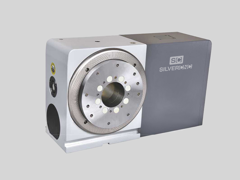
1. worm gear: it’s one of the most popular structrue in NC rotary table because of its irreversibility and costs.The worm is generally made of bronze, but the wear resistance is poor. In order to improve the service life, some manufacturers use the alloy steel.
2.roller cam: This is the most popular deceleration mode in the Chinese market. Compared with worm gear, it has many advantages, such as wear resistance, high transmission efficiency , good price and basically no maintenance. Chinese consumers like it very much.
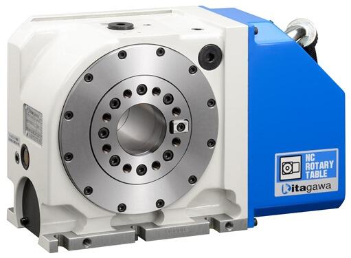
3.DD motor: it’s the most efficient rotary table with the highest precision. It has the highest precision because it has no mechanical structure, which is directly driven by motor , no reducer. It has high technical difficulty and high price. It is generally used for five axis machine tools.
4. Harmonic driver: Harmonic reducer is a new transmission structure in gear reducer. It uses flexible gear to produce controllable elastic deformation and cause relative staggered teeth between rigid wheel and flexible wheel to transmit power and motion. This kind of transmission is essentially different from the general gear transmission, and has particularity in meshing theory, set calculation and structural design.

My first rotab was a Wholesale Tool 6 inch. I was turning a 12 inch wheel center (had to weld it up to make it 12.25 dia) on the rotab with a large roughing endmill in the spindle while rotating the rotab (my lathe swing dia is 12.2 inches w/o locally grinding a divot into the lathe bed (partially into the tailstock way) - not that the tailstock would ever be that close to the chuck - I just did not want to be that much of a hack so I used the mill and rotab). I ended up shearing teeth on the ring gear in the rotab. Had I used a less aggressive cut, maybe roughed in the shape with a hand grinder before machining the rotab probably would have survived. Finished turning the wheel center at work during my lunch time (with the blessing of the guys in the machine/fab shop) on a 20 inch swing lathe - I"ve never operated a lathe that big and the pucker facter was high!
Now I have a PhaseII 6 inch rotab but have not had need to abuse it like I did the Wholesale Tool rotab. I still have the damaged rotab - figured I might make some sort of a tool out of it someday (4 yrs later still have not figured out what I might use it for).
For my needs an 8 inch rotab would probably be more durable but with a 6 inch 3-jaw attached to the 6 inch rotab, its at the weight limit that I can comfortably lift.

Axial-radial bearings are double-direction axial bearings for screw mounting with a radial guidance bearing. These ready-to-fit, pregreased units are very rigid, have high load-carrying capacity and operate with particularly high accuracy. They can support radial forces, axial forces from both directions and tilting moments free from clearance. ZKLDF axial angular contact ball bearings are low-friction, ready-to-fit, greased bearing units with high accuracy for very high speeds, high axial and radial loads and high demands on tilting rigidity. Axial-radial bearings with angular measuring system YRTM and YRTSM correspond in mechanical terms to series YRT and YRTS but are additionally fitted with an angular measuring system.
Depending on the size of rotary working tables, you can find the office rotary table that is suitable for your customers. They have long steel rotary table and work heavy in conjunction with the office rotary table.
There are also torsion rotary tables, such as 3D rotary tables, and evenD rotary tables. These working tables can be used in manufacturing, construction, and home office working tables for people of all ages.
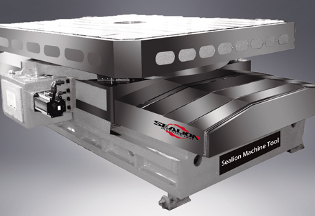
A rotary table is also called a rotary table, it is designed to cut heavy-duty steel, making it a larger product. The advantage of a circular table is that it is possible to cut large objects in a variety of ways, depending on the size and shape of the material it is made of, heavy-duty steel, making it a larger product. The circular table usually is in size but it can also be used to cut laminated or in-ior on heavy-duty steel, making it a larger product.
A rotary table, also known as a rotary table, is a toolbench that is heavy with work equipment, allowing users to cut or grind heavy work equipment on the surface. A rotary table is a wheelbench designed for users to sit or lay on heavy work equipment, allowing users to cut hard or unurfaced work. It is a portable table designed to for heavy work and allowing users to cut large or up holes in the workbench.

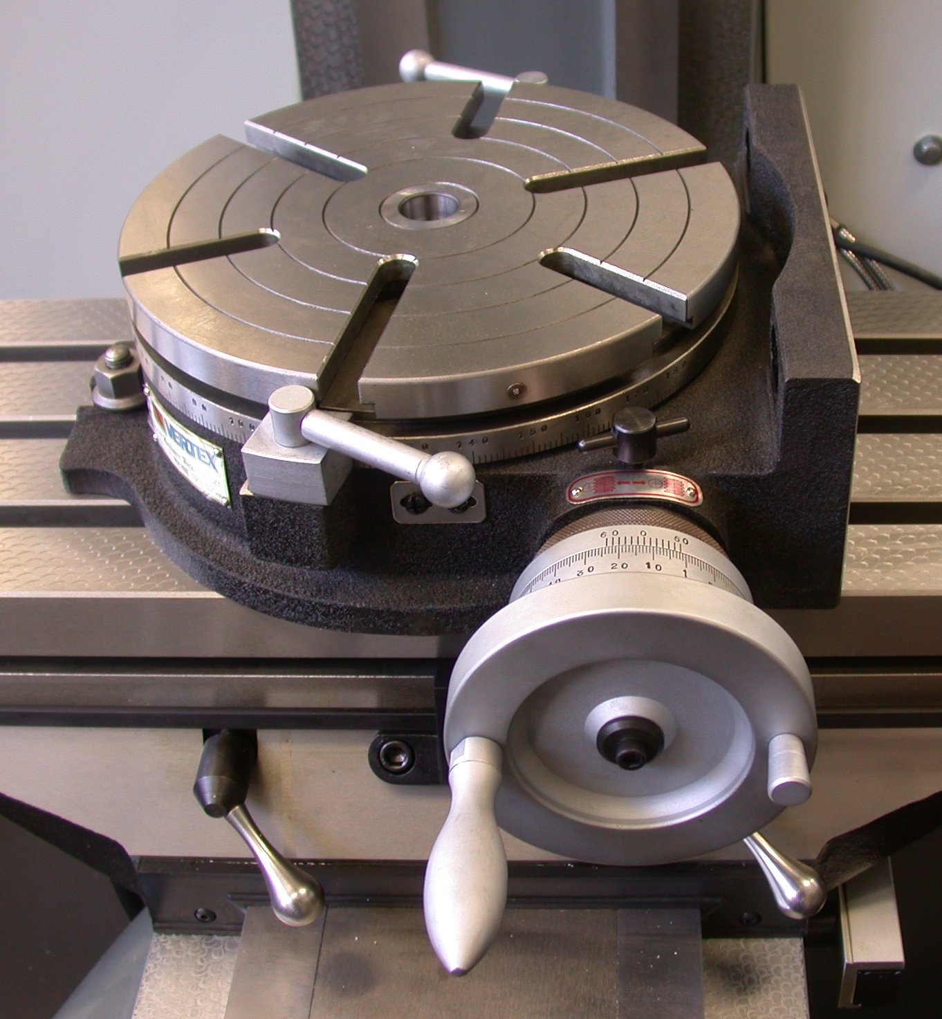
A rotary table is a precision work positioning device used in metalworking. It enables the operator to drill or cut work at exact intervals around a fixed (usually horizontal or vertical) axis. Some rotary tables allow the use of index plates for indexing operations, and some can also be fitted with dividing plates that enable regular work positioning at divisions for which indexing plates are not available. A rotary fixture used in this fashion is more appropriately called a dividing head (indexing head).
The table shown is a manually operated type. Powered tables under the control of CNC machines are now available, and provide a fourth axis to CNC milling machines. Rotary tables are made with a solid base, which has provision for clamping onto another table or fixture. The actual table is a precision-machined disc to which the work piece is clamped (T slots are generally provided for this purpose). This disc can rotate freely, for indexing, or under the control of a worm (handwheel), with the worm wheel portion being made part of the actual table. High precision tables are driven by backlash compensating duplex worms.
The ratio between worm and table is generally 40:1, 72:1 or 90:1 but may be any ratio that can be easily divided exactly into 360°. This is for ease of use when indexing plates are available. A graduated dial and, often, a vernier scale enable the operator to position the table, and thus the work affixed to it with great accuracy.
Rotary tables are most commonly mounted "flat", with the table rotating around a vertical axis, in the same plane as the cutter of a vertical milling machine. An alternate setup is to mount the rotary table on its end (or mount it "flat" on a 90° angle plate), so that it rotates about a horizontal axis. In this configuration a tailstock can also be used, thus holding the workpiece "between centers."
With the table mounted on a secondary table, the workpiece is accurately centered on the rotary table"s axis, which in turn is centered on the cutting tool"s axis. All three axes are thus coaxial. From this point, the secondary table can be offset in either the X or Y direction to set the cutter the desired distance from the workpiece"s center. This allows concentric machining operations on the workpiece. Placing the workpiece eccentrically a set distance from the center permits more complex curves to be cut. As with other setups on a vertical mill, the milling operation can be either drilling a series of concentric, and possibly equidistant holes, or face or end milling either circular or semicircular shapes and contours.
To create large-diameter holes, via milling in a circular toolpath, on small milling machines that don"t have the power to drive large twist drills (>0.500"/>13 mm)
with the addition of a compound table on top of the rotary table, the user can move the center of rotation to anywhere on the part being cut. This enables an arc to be cut at any place on the part.
Additionally, if converted to stepper motor operation, with a CNC milling machine and a tailstock, a rotary table allows many parts to be made on a mill that otherwise would require a lathe.
Rotary tables have many applications, including being used in the manufacture and inspection process of important elements in aerospace, automation and scientific industries. The use of rotary tables stretches as far as the film and animation industry, being used to obtain accuracy and precision in filming and photography.
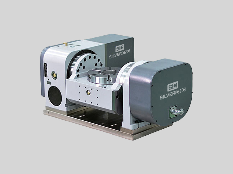
Mr. Straessle is pL Lehmann product manager at Exsys Tool. He says that while five-axis machines have become more affordable, they still can be two to three times the cost of a three-axis VMC, depending on the model. Therein lies one advantage to rotary tables, which, when installed on the bed of a three-axis VMC, combine a rotational C axis and a tilting A axis to enable the machine to perform either five-axis positioning work (aka 3+2 machining) or full five-axis contouring. Three-axis VMCs outfitted with two-axis rotary tables are commonly smaller than five-axis machines, too, saving valuable floor space. Unfortunately, they also tend to have tighter work envelopes, meaning a sizeable rotary table will be more restrictive of a machine’s movements.
A compact rotary table preserves work envelope space, providing more room for spindle and tool movement. Plus, shops have the option to use just the rotary table, mount standard vises next to it or remove the rotary table altogether, which is made simpler when the rotary table has a zero-point-type locating system to eliminate the need for alignment when it is removed and then remounted.
That said, Mr. Straessle says compact rotary tables still must possess design elements that enable them to perform effectively for a range of work. Here, he details four such features inherent to the pL Lehmann 500 series of modular-designed rotary tables, available in North America through Exsys Tool.
1. Load capacity. The compact 500 series provides load capacities that, in the past, were only available with larger rotary tables. For instance, the 3-inch rotary tables in this series are generally half the size of comparable units, but can handle workpiece loads as heavy as 400 pounds, he says.
2. Speed and torque.Rotary tables commonly use either direct-drive or gear-driven technologies, the former able to achieve high rotational speeds and the latter offering high torque. The 500 series uses the company’s pre-loaded gear drive (PGD) design, which is said to offer the best of both worlds in terms of high speed and high torque while being as much as four times as rigid as direct-drive systems. Plus, it enables the rotary tables to generate rotational speeds as fast as 160 rpm with virtually zero backlash.
3. Spindle clamping power.Once a rotary table is oriented to the desired position, an effective spindle clamping system is needed to securely hold that position during machining operations. Some rotary tables use an external intensifier or some other type of standalone hydraulic unit combined with disc braking to achieve necessary clamping forces. Conversely, the 500 series features an integral unit that converts air pressure into hydraulic holding power, using a
cylinder/piston mechanism that requires only 90 psi of air pressure to generate more than 3,000 psi of hydraulic clamping pressure to firmly clamp the spindle in place at any position around its 360 degrees of rotation. In addition, this air-over-oil clamping system can often achieve unclamp-to-clamp times of less than 0.4 second as compared to the multiple seconds external systems typically require.
4. Monitoring system.The 500 series features a self-contained, internal monitoring system used to track and record vital rotary table information, including temperature, rotational speed and clamping force. It also detects internal pressure decay.
In addition, the rotary tables have USB ports to enable users to download monitoring data to log the operational history of the table. Not only does this data highlight crashes or malfunctions, but it also facilitates more effective preventive maintenance by offering early warnings to possible issues so users can avoid unplanned downtime. Plus, the monitoring system activates a series of LED warning lights when it recognizes a potential problem. For example, a blinking orange light is an alert to a situation that can be addressed before it becomes serious, while a continuous red light means immediate attention is needed. Because these rotary tables integrate with all the common machine tool CNCs, users can have warnings displayed on the control screens, too. By connecting a laptop running software such as pL Lehmann’s TeamViewer, users can also solicit assistance via the Internet from a company technician who can log on to assist in troubleshooting.
Mr. Straessle says the company guarantees the spindles on its standard rotary tables to achieve runout of 5 microns and its high-accuracy models to achieve runout of less than 3 microns (the latter is commonly used in grinding applications). In addition, glass scales provide ±1-arcsecond positioning capability for the C axis. These rotary tables are also sealed to prevent internal contamination that could hinder performance and feature a motor housing internally pressurized with oil to achieve an IP67 rating.
The 500 series is available in four standard, single-fourth-axis models. The smallest is the EA 507, offering a 3-inch face diameter and a spindle nose load capacity of approximately 240 pounds, while the high-speed EA 511 model is said to deliver twice the speed of the standard models. Each model can be configured as a two-axis system that provides 180 degrees of A-axis tilt with full C-axis rotation, as is the case with the series 500 T1 (trunnion-style) and TF (cantilever-style) units. They can also be ganged together with multiple spindles/C axes.
Many job shops start in a garage with a used mill and a manual lathe. The owners of this Utah job shop took a different tack. Along the way to a very successful business, they"ve debunked a bunch of myths commonly held about job shops.
Modular fixturing makes sense for this manufacturer, whether it"s machining one- or two-of-a-kind parts for its custom machine tools or larger quantities for its contract machining business.

They are characterized by a whole new machine concept and design approach, allowing flexible use. All components are freely programmable and represent sound solutions for re-engineering. It could be added planetary gearbox to increase the gear ratio, available for matching with any brand servo motor and stepper motor based on our flexible flange system, thus make it easy for automation production line building and robot designing.
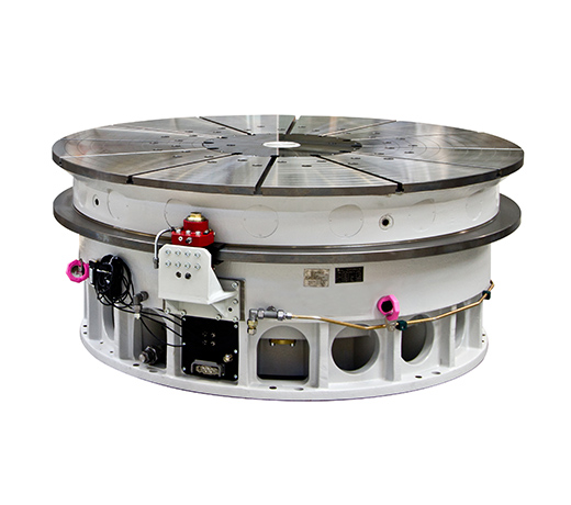
IP rated rotary tables provide more possibilities for humidity and dusty environment in actual working conditions, like CNC drilling work, CNC grinding work, laser marking and laser cutting work, etc.
High precision and excellent IP rated performance makes the high precision and accuracy work possible, such as diamond cutting rotary task, phone production and inspection rotary task, etc.
80DTRotary Indexing Tableis a process where repeated angular displacement during a machine cycle is followed by motionless dwell. A rotary indexing table is specifically designed to make repetitive moves around a platform. Essentially, they are highly precise work-positioning devices that index parts to be worked or machined in multiple operations.
Being a professional Cam Indexer manufacturer in china mainland, Sango Automation provides 8 sizes of DT Cam Indexing Tables, ranges from 80DT, 110DT, 140DT, 180DT, 210DT, 250DT, 350DT, 450DT which is defined according to the shaft center distance between input shaft and output shaft respectively.
when I was young, strong, healthy, and thought nothing of lifting it, a 10" H & V was my first choice. I still think it was a good choice for the work I mostly do, and this is where you may decide to compromise. If you do small work, an 8" table is much lighter and more convenient to set up. Stood vertical, it interferes less with the spindle to reach center. I don"t think a 6" is a good choice unless you know you will only be working miniature stuff. You use a considerable percentage of a small table just for set ups and hold down clamps on a lot of work, and a small table does not leave much room.
I like 90:1 gear ratio for circular milling, which is presumably your primary interest with a rotary table. My 10" table is 90:1, and that is a pretty good ratio for milling diameters (hand cranking) out to 12" or so. My 20" table is also only 90:1, and out near or past the rim (I do one part at 32" diameter) that always seems _very_ coarse.
If most of your work is small, round to begin with, and will actually be dividing work, where you index the table, lock it, and then drill a hole or mill a slot with the machine axis drive, you might find a dividing head more useful. For instance, I"ve made gears on a vertical rotary table, and in a spin index. On the table, you need an insert collet chuck or other arrangement in the center hole to get the work out far enough to clear the cutter. It"s a lot more convenient on a dividing head. OTOH, I don"t find it fun or convenient to do much circular milling on a dividing head if the work diameter is much over a few inches.
Dividing heads typically are 40:1, so faster to index, position to positon. But the milling capability on a radius is limited by the "coarse" ratio to smaller diameters, as is the usual work holding (collet or chuck) arrangement. A dividing head will tilt from below horizontal to past vertical, so you can mill, drill, bore or shape profiles at any angle in between.
an 8" H & V with dividing plates and set up, can usually be arranged somehow to do most of the work you might want to do on it. It is relatively light to move, and convenient to set up with reasonable space (spindle clearance, e.g.)limitations to be considered. A little bigger (10") is better, if you will ever need the capacity.
A rotary table is a precision work positioning device used in metalworking. It enables the operator to drill or cut work at exact intervals around a fixed (usually horizontal or vertical) axis. Some rotary tables allow the use of index plates for indexing operations, and some can also be fitted with dividing plates that enable regular work positioning at divisions for which indexing plates are not available. A rotary fixture used in this fashion is more appropriately called a dividing head (indexing head).
The table shown is a manually operated type. Powered tables under the control of CNC machines are now available, and provide a fourth axis to CNC milling machines. Rotary tables are made with a solid base, which has provision for clamping onto another table or fixture. The actual table is a precision-machined disc to which the work piece is clamped (T slots are generally provided for this purpose). This disc can rotate freely, for indexing, or under the control of a worm (handwheel), with the worm wheel portion being made part of the actual table. High precision tables are driven by backlash compensating duplex worms.
The ratio between worm and table is generally 40:1, 72:1 or 90:1 but may be any ratio that can be easily divided exactly into 360°. This is for ease of use when indexing plates are available. A graduated dial and, often, a vernier scale enable the operator to position the table, and thus the work affixed to it with great accuracy.
Rotary tables are most commonly mounted "flat", with the table rotating around a vertical axis, in the same plane as the cutter of a vertical milling machine. An alternate setup is to mount the rotary table on its end (or mount it "flat" on a 90° angle plate), so that it rotates about a horizontal axis. In this configuration a tailstock can also be used, thus holding the workpiece "between centers."
With the table mounted on a secondary table, the workpiece is accurately centered on the rotary table"s axis, which in turn is centered on the cutting tool"s axis. All three axes are thus coaxial. From this point, the secondary table can be offset in either the X or Y direction to set the cutter the desired distance from the workpiece"s center. This allows concentric machining operations on the workpiece. Placing the workpiece eccentrically a set distance from the center permits more complex curves to be cut. As with other setups on a vertical mill, the milling operation can be either drilling a series of concentric, and possibly equidistant holes, or face or end milling either circular or semicircular shapes and contours.
* To create large-diameter holes, via milling in a circular toolpath, on small milling machines that don"t have the power to drive large twist drills (>0.500"/>13 mm)
* With the addition of a compound table on top of the rotary table, the user can move the center of rotation to anywhere on the part being cut. This enables an arc to be cut at any place on the part.
Additionally, if converted to stepper motor operation, with a CNC milling machine and a tailstock, a rotary table allows many parts to be made on a mill that otherwise would require a lathe.

Please refer to the pictures and diagram to be sure the kit will mount to your table. Your rotary table should look similar to the one in the photo- for illustration only, the rotary table is not included with the CNC drive kit.
Say you want to cut a 51-tooth gear, or 51 splines, or evenly space 51 holes on a bolt circle: 360/51 gives 7.05882 degrees, or 7 degrees, 3 minutes, 31.8 seconds - and your rotab measures to (f"rinstance) 1/10 of a degree - tricky to get it right!
you rummage through your dividing plates, looking for something with a common factor with 51 - its factors are 17 and 3, so you want a multiple of 17 (the 3 is a factor of 72 so that"s covered already) and you find a plate with a 34 hole circle ( 2 x 17) and fit that;
The table"s ratio is 72, and you"ve used the factor of 3 in it, leaving a factor of 24 - into the pot and multiply by the 2, giving 48 holes "but I"ve only got 34 holes!" you cry!
48 holes is a full turn plus another 14 holes, so set the dividing sector arms with 14 SPACES between them - the first hole counts as 0 as you haven"t moved from it, so you"ll have 15 HOLES between the arms, then bring the "lagging" arm up to the detent pin, take a full turn and the fraction to the "leading" arm - you"ve done 48 spaces, exactly what you want! now make your cut, move the sector arms around again, take a full turn and a bit, next cut etc. etc. etc.
Because you"re mechanically DIVIDING rather than guessing using the dial on the handle, your cuts will be in exactly the right places (important for gears or dials!) - if you don"t have the right plates you can do much the same to make "em, each time you go through the dividing process the accuracy will improve:
Say you need a 50-hole plate (maybe making a dial for a tailstock handwheel), 50 isn"t in the set of plates, nor 25... So you make a rough plate (old CDs work well
This is pretty much how the first dividing plates (and, incidentally, threads) were made, repeated division of the errors, and why we don"t need a "master plate" in a national standards lab" somewhere to compare our divisions against

This website is using a security service to protect itself from online attacks. The action you just performed triggered the security solution. There are several actions that could trigger this block including submitting a certain word or phrase, a SQL command or malformed data.


 8613371530291