
how to make a rotary table manufacturer

For a corner fillet weld such as those, it may help if you grind off half of each corner on the slotted plates giving a 45 deg V. This will help to ensure the weld gets good penetration and strength at the same time as allowing you to retain the original edges for alignment.
Looks to me like you are using a 240V single phase welder. In Oz I would use a Satin craft 13 electrode as these have a slower flux than a Satin craft 12. This helps stop the flux from running into the weld pool and stopping the arc. My welder has only 2 settings 2.5 and 3.2 mm so I try and use the shortest possible cable between the power point and the welder. If I have to go longer a heavier duty cable helps keep up the volts and amps.

When autocomplete results are available use up and down arrows to review and enter to select. Touch device users, explore by touch or with swipe gestures.

At Rusach International,rotary table design, engineering and manufacturing & pallet system design, engineering and manufacturing is our specialty. We can supply rotary tables from 100mm up to 8 Meters in diameter. See our rotary table pages. We specialize in high accuracy, up to +/- 1 arc second, heavy load capacity, large work pieces, production style, heavy duty rotary tables and pallet shuttle/storage/transfer systems. We also have a line of standard small production tables that are very cost effective, yet can be customized per application.
Rusach International systems are not proprietary and therefore can be integrated into any machine, control system or application. We do not believe in “locking” a customer down with proprietary parts! We work with all the major industry control, motor and encoder manufacturers.

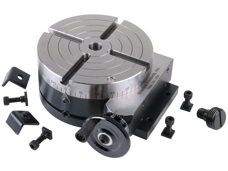
Manufacturer of standard and custom 360 degree linear rotary tables for scanning, assembly, testing and production applications. Features vary depending upon model, including worm and gear drive design with central rotating ball bearings, manual and motorized operation, hollow spindles, four mounting holes, accessible adjustment clamps and graduated knobs. Accessories such as rotating table adapter plates, brackets, platform shelves, thumbscrew locks, alternative knobs, limit switches provided. Manually operated rotary motion turntables also available. Suitable for mounting and rotation of test specimens, cameras, transducers, sensors, mirrors and other components. Stock items and repair services are offered. One year warranty. Made in the USA.

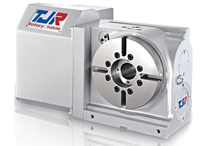
A CNC rotary table is the precision positioning accessory that can provide a reliable 4th axis or even 5th axis for modern machining centers. Utilizing a computer-controlled rotary table can turn the original 3-axis machine tools into 5-axis CNC machines, expanding the accuracy as well as decreasing the costs while performing complex machining operations at one time.
A CNC rotary table is the precision positioning accessory that can provide reliable 4 or even 5 axis cutting operation capabilities for modern machining centers. Utilizing it can turn the original 3-axis machine tools into 5-axis CNC machines, expanding the accuracy as well as decreasing the costs while performing complex machining operations.
Rotary tables typically have rigid frames and coatings, and also excellent torque capacity, which makes the small device flexible and effective for a wide variety of turning, milling, drilling, and more metalworking operations. The easy setup and seamless interface allow the operators to easily add the rotary table to fit their 4-axis or 5-axis applications. .
The working principle is similar to the basic rotary tables, which is to support the workpiece by accurately rotating the workpieces on the axis in order to locate the parts for high precision tooling. Under rapid rotation, which is driven by CNC instructions, the cutting tools of larger machine tools or machining centers can remove the material and add the feature to the products at exact intervals. On rotary tables, there are vertical and horizontal axes for various tools to perform these high-performance metalworks. To enhance the accuracy and flexibility, there are models that employ additional dividing plates and come with additonal material handling mechanisms and features.
Since 4-axis and 5-axis machining is increasingly popular today, adding the CNC rotary table as the 4th axis is an ideal solution to easily open up more complex machining options at a lower cost. Due to the arrangement, they are widely also called the 4th or 5th axis or tilt rotary. The 4th axis, which is the rotational operational direction, is added to the original three linear axes which are known as X-axis, Y-axis, Z-axis. In some cases, there are two rotational axes add to the original 3-axis machining center, achieving utmost accuracy as well as effective multiple face cutting to reach the difficult area on the surface. Rotary tables are usually mounted parallel to the ground or the bed, with the platter rotating around the vertical axis, for example with the most common vertical milling machine combination. Sometimes the machining application requires an alternative setup with the table mountet on its end so that it rotates around the horizontlal axis. Often, a tailstock is used in this configuration. Virtually all models today come with a clamping kit to mount it onto the bed of your machine tool.
The function of the high precision rotary table is also to rotate the workpiece so the cutting tool can create the contour we desired out of the workpiece. However, a rotary table with higher precision has the ability to achieve great accuracy just as its name implies. There is also a major misconception between the resolution and the accuracy.
A common example is that if a digital readout displays to four decimal places, then the high precision rotary table must also be capable of achieving the accuracy to that same value. Even though for higher accuracy to be achieved, the resolution has to also be high, but there is no guarantee that the accuracy is going to be high. The accuracy is the concept which is the difference between the actual position and the position measured by a reference measurement device. The feedback mechanism such as the rotary encoder, and the drive mechanism can influence the accuracy of the advanced rotary table.
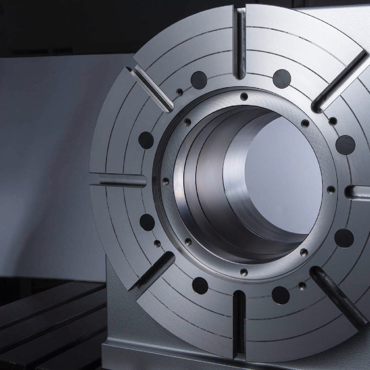
A CNC rotary table can provide great rigidity for stable machining operations. It consists of the worktable where the metal parts are held, the rigid bearing that withstands the forces and loads during the rotation, the solid base which is used for attaching the rotary table to the machining center or other equipment, the motor, and the CNC system.
The worktable is the tooling surface where the workpieces are machined after accurate positioning. The worm gearing is the core mechanism of the table, which mesh with the steel worm which is submerged in the lubricants. Both the rigid bearings and the worm gears have large diameters. Excellent concentricity is the key to smooth operation, durability, and most importantly, accuracy. Driven by a computer and electric motor, the worktable can position the materials at exact intervals. For more flexible or critical operations, dividing plates can be added to this component.
A CNC system regulates the simultaneous 4-axis motion of the rotary table. The instructions are programmed and transmitted via CAD software, reducing the time for adjustment and monitoring by human workers.
The type and size of the electric motors utilized in can define the router accuracy as well as the efficiency of the device. Servo motor and stepper motor are two typical types that can be divided into more subtypes. The servo motor uses a closed looping variable circuit, the circuit will constantly run to keep the function. The brushes must be replaced every 2000 hours of operation in the servo motor. Compared to stepper motors, servo motors are more efficient in power consumption. On the other hand, the stepper motor has a simpler setup which are the wires that are attached to the driver. The bearing of the stepper motor is the only wearing component. However, the stepper motor consumes a great amount of energy.
There are currently several different types and models available in the industries. Each of them possess its own traits and abilities. Let us take a look at the most common ones other than standard three axis tables
The 4 axis CNC rotary table will process the workpieces by holding them in the same position while the cutting tool performs along the XYZ plane to trim away the unwanted material. In general, a 4 axis model is very versatile equipment that can be used for several different industrial processes such as engraving curved surfaces, continuous cutting, and intermittent cutting. Besides, people can also add other devices such as cam machining, blade machining, and helical grooves to the 4 axes rotary table. Such a feature is simply impossible to achieve with the machining center which has only 3 axes.
Besides the 4 axis ones, there are also 5 axis models. They have the ability to allow the workpiece to be processed automatically from five sides at one time. people usually utilized the 5 axes rotary table in the industries such as the automobile, the aerospace, and the boating industries. The reason that the 5 axes rotary table is commonly used in heavy industries is that the 5 axis machining is an important technique to be used when the components need better intricacy and quick precision. All of these have more than three axes are called the multi-axis rotary table.
The installation method of the precision rotary table can be horizontal, vertical or inverted. When installed horizontally, the workbench surface is in a flat, vertical and horizontal position. When installed vertically, a rotary table is installed so that the surface of it can run up and down. In the reverse layout, itcan be rotated upside down in a horizontal position. The location of the drive of the rotary table can depend on the mount. The drive can be placed on the back, below, on the top or on the side.
When mounted horizontally, the spinning table top drive is positioned above the table floor. When the rotary table is horizontally placed, the side-mounted drive is located on the edge of the table board. The driving mechanism of the rotary table may be manual, electrical, pneumatic, hydraulic or non-driven. For manual revolving workbenches, release the workbenches and manually spin the workbenches with the crank.
Workpieces are gathered and machined through PC and fully programmed instructions. The 5-axis simultaneous operations will be measurably more reliable than products machined via different technologies. Also, the setup is simple and provides an indistinguishable process in every production cycle, the consistency of the quality of the metal products can be ensured under critical control and precision cutting.
Since the metalwork is driven by software, the preferred frameworks can be programmed and adapted by the rotary table. Saving both the cost and the room makes themis the ideal solution for potential users who don’t want to install larger equipment and new machines which may take up a great room for a wide variety of machining applications.
Another benefit is the utmost movements can be completed precisiely and faster. There are more favorable positions, operation angles as well as accessible machining that can be achieved through the technology. The complex operations are suitable for blade, helical grooves production, and other applications required to add complex features or require critical inspection in machining processes like the manufacturing of aerospace, automotive parts, and scientific equipment.
Addding a rotational table saves time because the extra finishing jobs or other sub-operations can also be performed at one time in the machining center.
A rotary table can be used in many applications including manufacturing, inspection, and assembly. Indicators are used, for example, for assembly, manufacturing, and bottling equipment. They typically use a single item in workspaces or move relatively small layouts of items around stations for sequential work or assembly.
In automated assembly machines, the rotary tables implementation is widespread, and choosing the right mechanism is important for both improving efficiency and reducing the cost of this vital component. This guide discusses two common devices for rotating indexing and offers guidance on the right range. There are several ways to get mass mobilization when it comes to the development of rotary indexing tables. Regardless of whether the load or load in centuries of thousands of kgm2 is incredibly light. When choosing a robust rotary index solution that will match or meet your standards, there are several factors to take into account when spinning, elevating, or pushing.
When determining the influencing factors on the postitioning accuracy, the first thing to look at is the mechanical properties of the table itself. A rotary table contains six degrees of freedom. Each of these movements increases the total risk of positioning errors. Usually, a rotary table is driven by a worm gear, which is connected to the motor through a rotary encoder on the back. The position of the table can be determined by the number of pulses transmitted from the encoder to the control device.
The four main sources of error due to the semi-closed position loop are geometric errors, thermal deformation, elasticity, and wear. The sum of these errors is called angular positioning error. To greatly reduce the angular positioning error, the ideal position for installing the angle encoder is on the rotating shaft under test. The angle encoder is installed under the rotary table, and the rotary encoder is installed under the rear motor, the position loop is now considered a closed-loop system.
Precision is a relative term. About a quarter of an inch is great and will meet the accuracy of its application. Others, for example, require micron-level accuracy in measuring and indexing devices. Then, some applications fall within these extreme ranges.
The misunderstanding is that you may have used an inaccurate indexing device and made it accurate by introducing a pin or wedge locking device. These devices increase the complexity and cycle time of use, and when they are used together with a high-precision positioning device, they may cause damage and reduce accuracy.
In the actual test, by selecting specific components, motion index drive, servo rotary indexer, the measurement accuracy is as high as 5-6 microns. These are not the results approved by Motion Index Drives, but the results of customer certification. When starting and stopping large amounts of data, it is important to know how fast it takes to stop the application with large amounts of data.
In a less rigid environment or the presence of higher recoil, a faster start and stop will bring many control problems. When moving masses (whether rotating mass or linear mass), starting and stopping in a system with a backlash of several arc minutes will cause a lot of back and forth movement in the gear system. The result is a force that is difficult or even impossible to calculate. In addition, when the gear head is used in rotating applications, the farther the mass is from the center of rotation, the greater the backlash. In applications with very slow deceleration times, recoil may not be a problem.
Backlash in the positioning process is a big issue – when it comes to the beginning and stopping volumes, it"s crucial to know how quickly you need to avoid the mass of your rotary indexing table applications. In a less rigid system or where there is an increased backlash, quicker start-ups and stops can cause a lot of control issues. When shifting a mass, whether rotary or linear, starting and stopping in a system with several minutes of backlash arc will create a lot of back-and-forth motion within the gearing system. The effect is a power that can be difficult and probably hard to quantify. In comparison, as the gear head is used for rotational applications, the more the mass is from the axis of rotation, the further the backlash is magnified.
The backlash may not be a concern in systems where deceleration times are incredibly long. In the case of cam indexers, there is " Zero Backlash." The cam indexer and rotary table dynamics give an incredibly rigid, highly regulated framework. A modern cam indexer system is capable of withstanding short cycle times with stop times in milliseconds.
So you want to get the smart manufacturing going but are not sure of what to look for in rotary tables. The information provided in this section may be able to help. The primary factor is to determine the mass snapshot of inactivity. This is often overlooked when measuring a rotary table for the machine.
Another significant factor is the size of the workpiece being rotated, including how big it is and how substantial it is. You want your rotary tables to be large enough to handle enormous pieces. This is where tilling rotary tables may become handy so that the pieces can be handled without causing interior harm. They allow the quickening and decelerating of machining at appropriate rates.
The last factor is accuracy, the applications for which, for instance, pivoting a gigantic part to allow welding highlights on it where the individual stop positions can be genuinely free. On an additional note, when choosing direct drive rotary tables, factors that you should consider when selecting a rotary table for your CNC machinery include accuracy, backlash, mass moment of inertia, acceleration and deceleration, speed, and environment.
Indexing system use is commonly possible in automatic assembly machines and the right process is important for both performance maximization and cost reduction.
Cam indexers are an omnipresent tool used for several decades for rotary indexing tables. They are suitable for applications that often index the same angle and need a high degree of accuracy at a relatively low cost. To place the load, a cam indexer uses a mechanical cam. A math curve is pushed onto the cam and provides incredibly smooth and repeatable movement.
Another popular alternative is a fully programmable rotary index table. A rotary table is advantageous in two different situations. Firstly, a versatile movement pattern is important. An example is if two components are running on one computer, each of which requires different index patterns. For incredibly fast placement accompanied by a long period, another condition that matches the servo pointer is. The need to accelerate the camshaft while the cam indexing mechanism was operating before starting the output movement reduced the on-demand cam indexer. Acceleration of the camshaft is possible, but there is a delay before the movement begins. There are realistic restrictions.
With an indexing table, the output rotates as soon as the servo starts moving. This is not difficult for a continuous cam indexer or a zero-backlash servo indexer, but it can also be difficult for an on-demand cam indexer. For applications with high-speed servo indexing, smooth movements are crucial. A zero-backlash preloaded reducer can achieve this. The ideal alternative for correct positioning with high dynamic response would be the zero-backlash reel drive system.
Application parameters, like a moment of inertia, indexing angle, indexing period, and residence time, are required for each indexer style. The rotary indexing table for the application should also be sized correctly by a reputable manufacturer.

Tilting rotary tables are mounted on milling machines to provide the user with two additional axes for machining operations. A tilting rotary table is an economical way to give a three-axis mill five-axis machining capabilities.
These devices are generally found on three-axis CNC machining centers. They are used mostly for machining small parts, and can perform light to medium-duty cutting operations. They are used in the automotive and aeronautical industries to manufacture parts such as carburetors and turbine blades.
Tilting rotary tables resemble rotary indexing tables with an additional rotating axis. They can either be manually actuated or CNC controlled, the latter requiring two additional interface cables to control all five axes.
Kitagawa"s new GT200 rotary table is a through hole unit capable of withstanding high cutting loads. It features a 200mm diameter table and provides ...
The TRT70 is a dual-axis tilting rotary table that offers high-speed, accurate performance for 3+2 and full 5-axis machining of small parts. It fits into the CM-1 or ...
100 mm (3.9") High-Speed Tilting 2-Axis Rotary Table, with indexing up to 1000 deg/sec. Requires a Haas mill with 4th- and 5th-axis drives for true 4th- and 5th-axis ...
The TR500SS is a high-speed, dual-axis trunnion rotary table that offers maximum rigidity and accurate performance for 3+2 and full 5-axis machining of large parts.
... X-RSW-E Series products are motorized rotary stages with built-in controllers. Rated for 2.25 N-m of torque, speed up to 75 rpm, and a load capacity of up to 20 kg, these stages ...
At a total height of 21 mm, Zaber"s X-RSM-E Series rotation stages are our most compact stepper and worm gear driven devices. These devices have 0.02° repeatability, an aperture of 4 mm, and a load capacity of 50 N. Self-aligning ...
... , photonic component alignment, high-accuracy laser machining and precision wafer inspection. These rotary stages can also be configured as multi-axis gimbals.
... Tilt-Yaw (A/B) two-axis rotary assembly provides high-speed machining capabilities for complex 3D part geometries. The precision-aligned system allows accurate positioning on a hemispherical ...
... ) MDR two-axis rotary assembly provides high-speed machining capabilities for complex 3D part geometries. The precision-aligned system allows accurate positioning on a hemispherical surface. ...
This is the smallest CNC Rotary Table manufactured by Nikken Kosaksuho in Osaka, Japan. With pneumatic clamping this rotary table is used by many on their small vertical ...
... secured. High positioning accuracy ensures precise results for 5-axis machining. KESSLER`s very latest torque motor generation, the ultra-flexible rotary and rotary tilt tables ...
... Drive Rotary Table is a kind of rotary table used to the continuous operation which is several times more agile and accurate than conventional face gear or rack and pinion ...
With DirectIndustry you can: Find the product, subcontractor or service provider you need | Find a nearby distributor or reseller| Contact the manufacturer to get a quote or a price | Examine product characteristics and technical specifications for major brands | View PDF catalogues and other online documentation
Indexing tables are used in a multitude of industries and in numerous applications. Their design is optimal for many manufacturing jobs, and they are a critical component in most automated manufacturing systems. Indexing tables are best defined as a machine tool positioning device. They carry components in a manufacturing environment with a repeating process of indexing (rotating) around an axis, stopping, dwelling while an operation is performed, then indexing again to repeat the process. They are usually made of circular steel plates, with one or more spindles, a drive system, encoders, sensors, controllers and slots or mounting holes to hold components.
Virtually any manufacturing operation can be performed on a part held by an indexing table including welding, grinding, drilling, assembly, painting, inspection, testing and more. In order to maximize operational efficiency, the machine doing the operation must also be built for the same intended application as the indexing table for them to work in synch. Similarly the machine that loads the indexing table with parts must also be synchronized. They must have the same capacity and be able to manage to the same dwell time for the system to work.
If the timing of these machines are coordinated, the time to operate on or assemble a product can be a fraction of that of workers assembling a product.
Industries that use indexing tables include automotive manufacturers, bottling companies, microchip manufacturers, pharmaceutical makers, consumer products companies and many more. They are invaluable to manufacturers pushing for automation and increased efficiency in their factories, turning work that used to take days into work that takes only hours. If a simple assembly task is required on small parts in a factory, there is no better way to complete the task than by coupling an assembly tool and an indexing table.

TANSHING products can be selected depending on different machining conditions. A wide range of models, such as the type of high load, high rigidity, high speed, high precision, long life span, zero backlashes, ultra-high load 10-60 tons large precision rotary table, and hydrostatic table can be customized. In addition, there is a variety of new 5 axis rotary tables, swing head rotary, etc. The complete series is available in our product line.
TANSHING’s R&D team is capable of dealing with a variety of machining requirements, such as speed and load capacity improvement. Any customized accessories can be planned and designed quickly. The same type of rotary table with a direct drive motor has been widely installed at domestic and foreign machine tool manufacturers. Our techniques for the function application of product, assembly, and testing are well-developed. We welcome machine tool manufacturers and machining shops to contact us for any kind of inquiry.

There are manual and motorized stages, open-loop and feedback stages, and stages of various sizes, so it is important to select the right one for each application.
In addition, since rotary motion is often performed for the purpose of processing, measurement, or some other subsequent operation, the use of rotary tables by themselves is rare.
Since the rotation stage itself can be mounted in various directions, it is used to determine whether it is more efficient to rotate the object to be processed or measured or the mechanical parts of the equipment.
High-precision rotation is required depending on the application, such as manual coarse rotation when a rough angle is required, and fine rotation when fine angle adjustment is required.
Rotation mechanisms used in chairs and other equipment are also classified as rotary stages in the broad sense of the term, so they are used not only in manufacturing but also in home applications.
A crossed roller bearing is a bearing structure in which rollers are arranged between the inner and outer rings. The rollers are arranged in a straight row with a 45° contact angle, enabling the back bearing structure of a ball bearing to be realized with a single row, and the structure is capable of receiving loads from multiple directions simultaneously. The rotary table and cross roller bearings can be directly connected, which reduces the number of structural parts.
Since the rotational accuracy of the rotary table is directly related to the accuracy of the rollers, high rotational accuracy can be obtained depending on the accuracy grade of the rollers. In addition, since cross roller bearings have low frictional force and can be operated with light force, micrometer heads can be used in the fine-tuning rotation mechanism to obtain high positioning accuracy.
We use cookies and tracking pixels to personalize content and ads, provide social media features, and analyze traffic to our Website. We also share information about your use of our site with our advertising and analysis partners. Our partners may merge this information with other information you have provided to them or collected while using their Services. By clicking the "Agree" button, you consent to the use of cookies or tracking pixels in the selected categories. You can decide which categories you want to allow. Please note that based on your settings, it is possible that not all functions of the site are available anymore. You can find more information in our privacy policy.

Many rotary table manufacturers outsource gear fabrication to lower costs. While that strategy may offer short term cost savings, Index Design’s American made rotary tables are built with gears cut in house. This is the only way to closely monitor and control tolerances, consistency and performance.
Our rotary tables incorporate large diameter high tensile bronze worm gears mated against hardened steel drive shafts. The combination of metal gives superior wear properties for long lasting operation. As the rotary table is run, the properties of a tin bronze gear develops a low friction deposit on the mating steel drive shaft. These deposits fill in microscopic pores of the mating surface. Over time, as these deposits are embedded on the surface, wear decreases followed by a reduction in frictional forces within the gear assembly.
Final inspection and verification of specification performance is done with precision calibration equipment capable of measure tolerances of +/- 1 arc second in any position. Any deviations from specified angular positions are corrected so our customers can be assured that they are receiving the performance we guarantee.
In addition, the data gathered from our automated calibration procedure allow our engineers to assess, monitor and improve the static and dynamic performance of prototype rotary tables during the design phase.
Our engineers have a long and rich history in the machine tool business, they combine decades of both CNC machine tool and rotary table manufacturing experience with the latest design tools to produce rotary tables with superior performance and dependability.
Our CAD/CAM software is used to analyze displacement and stress for each component, sub-assembly and total assembly. However, the best software and technology is worth next to nothing if no one understands the craftsmanship. This is particularly true when manufacturing precision rotary tables which involves many steps. Despite all the modernization and automation available, a large part of the manufacturing process is still completed by hand. At Index Designs, we understand and appreciate craftsmanship, It is designed and built into our products.

Malad West, Mumbai 21, Shripal Services Industrial Estate, Pawan Baug, Chincholi Phatak, Off. S.V.Road, Malad West, Malad West, Mumbai - 400064, Dist. Mumbai, Maharashtra
DELHI,NCR,HARYANA,PUNJAB,UP,RAJASTHAN, Dharuhera, Dist. Rewari 347, Ganpati Plaza, NRP Bass Road, DELHI,NCR,HARYANA,PUNJAB,UP,RAJASTHAN, Dharuhera - 123106, Dist. Rewari, Haryana
Sector 37D, Gurugram, Haryana 122006, Gurgaon, Dist. Gurugram Nath Tools Company , Garauli Khurd, main Pataudi Rd,, Sector 37D, Gurugram, Haryana 122006, Gurgaon - 122006, Dist. Gurugram, Haryana
Airoli, Navi Mumbai, Dist. Thane Krishna Kanhaiya, Sector No. 8, Plot No. 21, Shop No. 12 Ground Floor, Airoli, Airoli, Navi Mumbai - 400708, Dist. Thane, Maharashtra
Industrial Area Phase 1, Chandigarh 58 Industrial Area Phase-1 Chandigarh, Industrial Area Phase 1, Chandigarh - 160002, Dist. Chandigarh, Chandigarh

CNC rotary tables play a vital role in the performance of multi-axis machining centres. As table accuracy and reliability are of paramount concern throughout the product"s lifetime, Matsumoto Machine Corporation (MMK) has taken a pragmatic two-pronged approach to reducing indexing errors and improving performance. By enhancing both product calibration and encoder technologies the company has set new standards for rotary table accuracy.
Founded in Japan in 1948, Matsumoto Machine Corporation is a technology-leading provider of innovative, high quality jaw chucks and numerically controlled rotary tables used by industrial machine tool makers throughout the world. A key feature of MMK"s CNC rotary tables is a patented worm and wheel gear assembly developed by OTT GmbH, Germany. Unlike double lead worm gears, the OTT worm and wheel gear is able to minimise backlash, ensuring outstanding accuracy and long life, efficiency and durability.
Shaped in order to maximise gear surface contact area, thereby reducing adverse surface pressure effects, the OTT worm gear teeth are split into separate right and left parts (shank worm and hollow worm) connected by a span ring. This unique structure enables backlash adjustment simply by reducing the distance between the two parts. This design also ensures that only one side of a worm gear tooth is in contact with the wheel gear, leaving a clearance on the other side. As a result, the 2-piece split gear design will not seize up, even with zero backlash.
A further advantageous characteristic of the MMK CNC rotary table is a large diameter through-hole in the table spindle. This greatly increases machine versatility and rigidity, supporting a wider variety of chucks and jigs and the machining of longer workpieces.
By enabling most metal-machining operations to be undertaken on a single machine, the benefits of MMK CNC rotary table are far-reaching. These include the time and cost saving of single machine set-up and single fixturing setup, reduced parts handling and the elimination of tolerance errors as workpieces pass from machine to machine.
Of critical importance in this one-hit machining centre scenario is ensuring the high accuracy of CNC rotary table indexing and control throughout its working lifetime.
As with any form of precision equipment that is integrated into a machining centre by a third party machine tool maker, and which in turn is used by an end user in any number of industrial sectors, assuring consistent accuracy and performance over time presents a challenge.
As with a machine tool"s linear XYZ axes, the rotary axis is just as susceptible to uncontrollable events that may introduce angular positioning or axis alignment errors. Risking the production of defects in finished parts, these errors can be due to a number of reasons including, mistakes made in the initial machine installation, impact damage caused by collision or general wear-and-tear in use.
With its global reputation for product quality and design innovation, MMK therefore sought to equip its CNC rotary tables with a highly accurate and reliable means of tracking and controlling the indexing of its product throughout its lifetime, irrespective of the type of machine tool, workpiece complexity and duty cycle.
At the same time, in an increasingly competitive global market for CNC rotary tables, MMK also wanted to further enhance its product quality inspection processes. Specifically, the company set itself the task of augmenting index angle measurement as a key component of pre-shipment quality assurance procedures.
To provide machine tool makers and users with the ability to accurately track and control CNC rotary table indexing, MMK elected to integrate Renishaw"s super-compact TONiC™ non-contact optical incremental encoder system. Simple to install and with a compact readhead measuring just 35 mm x 13.5 mm x 10 mm, the TONiC encoder presented MMK with a minimal footprint solution capable of supporting machine speeds up to 10 m/s and resolutions down to 1 nm.
The rotary table readhead was designed to be used in conjunction with Renishaw"s RESM, a one-piece stainless steel ring marked on its periphery with 20 µm pitch graduations and featuring the IN-TRAC™ optical reference mark. With its low profile, large internal diameter and wide choice of diameters from 52 mm to 550 mm, the high stability RESM ring provided MMK with a versatile and easy to integrate scale that is well-suited to the company"s wide range of CNC rotary tables.
For improved reliability and higher immunity to any scale degradation over time, the TONiC readhead incorporates third generation filtering optics, tuned for low noise (jitter) and further enhanced by dynamic signal processing. The outcome is an ultra-low sub-divisional error of typically ±30 nm. The TONiC encoder is compatible with industry standard controllers and features a detachable analogue or digital interface inside a robust D-type connector, which can be located up to 10 m from the readhead.
MMK selected Renishaw"s compact and lightweight XR20-W rotary axis calibrator to verify the accuracy of its rotary tables during manufacturing and immediately prior to shipment. The XR20-W was used in conjunction with Renishaw"s XL-80 laser interferometer to provide a non-contact reference measurement, independent of the axis under test, with an accuracy of ±1 arc second.
Motorised by a servo-controlled drive and with data capture synchronised to axis movement, the XR20-W requires no operator intervention during measurement. Being lithium battery powered and Bluetooth enabled, it ensures quick and easy setup, and the avoidance of trailing cable hazards. The calibrator"s modular design and flexible mounting systems allow far easier setup than alternative solutions and can be readily configured for a wide variety of rotary tables, chucks and spindles.
By integrating Renishaw"s TONiC non-contact optical encoder system into its CNC rotary tables, MMK has further assured the accuracy and reliability of its products in the field, along with an overall superior motion control performance. For a wide range of different machine tools and end uses, the rotary tables" combination of compact readhead and one-piece stainless steel ring scale has delivered a higher level of tolerance to dust, scratches, grease and oil, and a reduction in indexing errors. The encoder system"s ability to output highly stable position signals of unrivalled purity and ultra-low sub-divisional error have provided smoother velocity control, improved scanning performance and increased positional stability.
MMK"s introduction of Renishaw"s XR20-W rotary axis calibrator and XL-80 laser interferometer has reduced product measurement times by a half compared to conventional autocollimator techniques. Measurement procedures have been simplified and automated. Capable of taking accurate measurements at any indexing angle pitch, the calibrator enables evaluation of the accuracy of the worm and wheel gear-driven table for ultra-fine pitch measurement movements as small as 0.001°. This has allowed any loss of motion control or worm and wheel gear efficiency to be evaluated in detail and addressed. Product performance is now backed by a thorough analysis meeting ISO quality standards.
CNC rotary tables play a vital role in the performance of multi-axis machining centres. As table accuracy and reliability are of paramount concern throughout the product’s lifetime, Matsumoto Machine Company has taken a pragmatic
two-pronged approach to reducing indexing errors and improving performance. By enhancing both product calibration and encoder technologies the company has set new standards for rotary table accuracy.


 8613371530291