
how to use a rotary table supplier
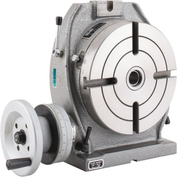
The rotary table is simply a round flat surface that can be rotated. What makes it interesting is that the table is driven round using a worm and wormwheel arrangement. This means that if a workpiece is mounted on the table it can be machined as it rotates.
On a rotary table the ratio between the worm and wheel is often about 40:1 on a small table but increases with the size of the table. For example a 360mm (12-inch) table might have a ratio of 120:1.
Rotary tables are calibrated round the edge in degrees and have a handle which turns the worm and which, in turn, will rotate the table by 360º divided by the ratio of the worm and wheel. For example, a 360mm (12-inch) table with a 120:1 worm and wheel will rotate by 3º per turn. The handle mechanism has a rotating dial and a Vernier so the angle, on a larger rotary table, can be measured to a few minutes.
Naturally any worm and wheel arrangement on a rotary table is likely to have some backlash. Sometimes this can be compensated for by adjusting the distance between the worm and wheel. Usually any backlash can be ignored if the movement, when machining, is always one way.
The same mechanism can sometimes be used to disengage the worm from the wormwheel. This is useful on large rotary tables because it enables the user to turn the wheel quickly to get from one position to another. (It is not possible to machine the workpiece whilst doing this.)
All rotary tables have a hole in the middle of the table. This is usually a parallel-sided hole but some, especially on smaller rotary tables it is tapered.
This hole can be used to take spigots that can be used to align the rotary table or align the workpiece on the table. Sometimes it is possible to fit a bolt through this hole using various spacers, washers, etc to hold the workpiece on the rotary table.
It is possible the get a device that has a taper on one end that is designed to fit the taper as found on some small rotary tables. The other end has a thread that is designed to fit the backplate as used on the chucks used on some lathes.
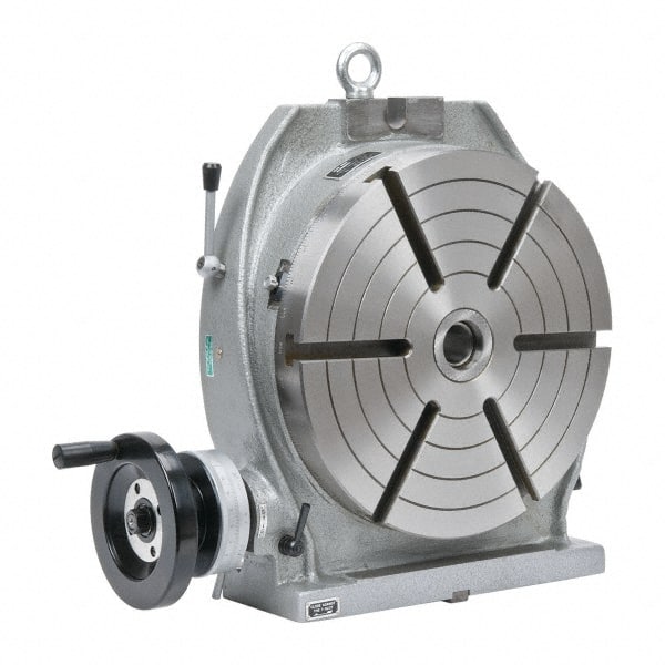
All rotary tables can be mounted in the horizontal position on the milling table. Some are designed so they can also be mounted vertically without any other hardware.
Most have slots in the base so they can be bolted to the milling table. Some do not but have a flange so that they can be clamped to the milling table.
It is possible to buy rotary tables that have the facility to tilt the table built in to them. Some even can be tilted at any angle in either or both of two planes at right angles. But all of this adds significantly to the height and weight of the rotary table.
The usefulness of being able to tilt in two planes is very limited and would probably not justify the space it would take up. But a rotary table that tilts in one plane can be useful. This setup can easily be emulated by fitting a rotary table to a tilting table.
Most rotary tables have some means of locking the table at any particular position. Very often an operation is done whilst the table is being rotated in which case the force of the cutter cancels any backlash. However when an operation such as drilling is being done at a particular point then the table should be locked.
Very often a cut needs to be made between two points at the ends of a particular arc. Usually it is not possible to make the cut in one go but several passes are needed. In this case it is useful to have two stops so each cut will start and stop at exactly the same points. This is very useful for preventing mistakes.
The fig. shows a stop. The movable part clamps to the top of the rotary table’s table. Two of these are needed. The fixed part has been fitted to the hole normally used for the locking mechanism as shown in the previous fig.
It will be noticed that the same hole on the rotary table is used for both locking and for a stop. But, of course, in practice, it will, at any one time, only be needed for one function or the other.
For milling any particular workpiece on a rotary table one has to allow for the space around the workpiece for the clamps used to hold it. For example a 200mm rotary table might hold a workpiece that had to have 120mm hole cut into it. It will be shown later how to effectively extend the diameter of a rotary table. It is often desirable to get the largest rotary table that will fit the milling machine table. However larger rotary tables can be very heavy.
With a large milling machine the practical limit is probably the largest you can lift safely. It is possible to have some sort of lifting gear but this all takes time. It is worth looking carefully before buying because for a given diameter, different makes or different methods of construction can cause a rotary table to vary dramatically in weight.
There will usually be enough space between to milling table and the cutting tool to fit a rotary table to do any required job. But there is always the height of the workpiece to consider. If other devices are to be mounted on the rotary table then the space rapidly disappears.
Most rotary table are set up as shown above to be rotated by a certain number of degrees. This is done using the calibrations on the table marked in degrees.
If it is necessary, when using a rotary table to divide a circle into a number of equal sectors then it is necessary to divide 360º by the number of sectors required. On a small rotary table, the table might only be calibrated to 5°. On larger ones they might be calibrated to individual degrees round the edge but will have a vernier arrangement on the handle so they can be set to a certain number of minutes. This gives us the angle between the sectors. Each time we move from one sector to the next we have to add the angle per sector onto the last angle. For any but the simplest numbers, the chances of getting this right are not great.
It is possible to have dividing plates fitted to a rotating table, as shown above, but this is unusual. But since dividing plates are always fitted to dividing heads these will be covered under dividing heads.
It is quite common to need to be able to divide a circle into so many parts. With dividing plates this is easy and is covered elsewhere. for a rotary table using just degrees and minutes a circle can be divided by one of the following methods.
A calculate the angle in your head or using a calculator for the origin for each sector and write them down. Most simple calculators will give decimal angles whereas the rotary table is marked in degrees and minutes.
B use a spreadsheet to produce a list of angles. These will probably be decimal angles. But is then quite easy to turn decimal degrees into degrees and minutes.
C Use tables showing the angles for each position for a circle divided up to 200 sectors can be found in Appendix C. These are in degrees and minutes.
D use the table for the first 200 sectors that can be found in “Tables for [the] Cooke Optical Dividing Head” published by Cooke, Troughton and Simms.
Manufacturer of standard and custom 360 degree linear rotary tables for scanning, assembly, testing and production applications. Features vary depending upon model, including worm and gear drive design with central rotating ball bearings, manual and motorized operation, hollow spindles, four mounting holes, accessible adjustment clamps and graduated knobs. Accessories such as rotating table adapter plates, brackets, platform shelves, thumbscrew locks, alternative knobs, limit switches provided. Manually operated rotary motion turntables also available. Suitable for mounting and rotation of test specimens, cameras, transducers, sensors, mirrors and other components. Stock items and repair services are offered. One year warranty. Made in the USA.

Indexing tables are used in a multitude of industries and in numerous applications. Their design is optimal for many manufacturing jobs, and they are a critical component in most automated manufacturing systems. Indexing tables are best defined as a machine tool positioning device. They carry components in a manufacturing environment with a repeating process of indexing (rotating) around an axis, stopping, dwelling while an operation is performed, then indexing again to repeat the process. They are usually made of circular steel plates, with one or more spindles, a drive system, encoders, sensors, controllers and slots or mounting holes to hold components.
Virtually any manufacturing operation can be performed on a part held by an indexing table including welding, grinding, drilling, assembly, painting, inspection, testing and more. In order to maximize operational efficiency, the machine doing the operation must also be built for the same intended application as the indexing table for them to work in synch. Similarly the machine that loads the indexing table with parts must also be synchronized. They must have the same capacity and be able to manage to the same dwell time for the system to work.
If the timing of these machines are coordinated, the time to operate on or assemble a product can be a fraction of that of workers assembling a product.
Industries that use indexing tables include automotive manufacturers, bottling companies, microchip manufacturers, pharmaceutical makers, consumer products companies and many more. They are invaluable to manufacturers pushing for automation and increased efficiency in their factories, turning work that used to take days into work that takes only hours. If a simple assembly task is required on small parts in a factory, there is no better way to complete the task than by coupling an assembly tool and an indexing table.
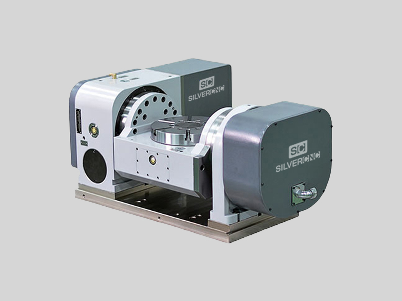
The TR160 5 Axis Rotary Tables, manufactured by Haas, consist of dual axis Trunnion rotary table that is capable of tilting up to 160 mm. It also has a scale assessment ...
The TR210 is HAAS"S rotary table developed and configured to be integrated with HAAS"S mills 4th and 5th axis drivers to provide complete and optimum operation. It has a diameter of 210 mm made from trunnion ...
... space with high load capacity. The individual rotary tables are equipped with Harmonic Drive units, which ensure high moment load capacities and high concentricity and axial runout accuracies.
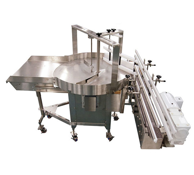
... accumulation turntables are made from the highest quality stainless steel and can be supplied in numerous sizes. They are utilized for the collection of filled bags, bottles and packages and can be added to an existing ...
The new CNC Rotary Table from GANRO has got higher speed and higher clamping torque. Thus making it suitable for machining complex components like turbine blades, when used ...
This is the smallest CNC Rotary Table manufactured by Nikken Kosaksuho in Osaka, Japan. With pneumatic clamping this rotary table is used by many on ...
The main part of the RollerDrive mechanism consists of an input shaft and an output turret in which roller followers are embedded. An integral cross-roller bearing supports the output turret with ...
... high-performance and flexible series from Peiseler. An extremely modern design with a good price characterises these NC rotary tables. The basis for this successful design is the complete ...
... Drive Rotary Table is a kind of rotary table used to the continuous operation which is several times more agile and accurate than conventional face gear or rack and pinion ...
CNC rotary tables of the ETS series are our solution for your 4th axis. The ETS models are equipped with a spindle holder according to ISO 702-1. Interchangeable discs for all common ...
Directly driven Motor Power Company"s rotary tables, provide versatile applications due to their backlash free structure. If necessary a compact servo system with high torque and high accuracy, SKA Rotary ...
... combination case of Large Aperture Rotary Table with planetary reducer with model number GSN200M-50K-SV which has table size 200mm gear ratio 1:50 for servo motor. GIGAGER provides combination ...
With DirectIndustry you can: Find the product, subcontractor or service provider you need | Find a nearby distributor or reseller| Contact the manufacturer to get a quote or a price | Examine product characteristics and technical specifications for major brands | View PDF catalogues and other online documentation
Rotary table in market mainly includes 4 kinds of mechanism that is worm gear, roller cam, DD driver and harmonic structure. The following is the introduction:
1. worm gear: it’s one of the most popular structrue in NC rotary table because of its irreversibility and costs.The worm is generally made of bronze, but the wear resistance is poor. In order to improve the service life, some manufacturers use the alloy steel.
2.roller cam: This is the most popular deceleration mode in the Chinese market. Compared with worm gear, it has many advantages, such as wear resistance, high transmission efficiency , good price and basically no maintenance. Chinese consumers like it very much.
3.DD motor: it’s the most efficient rotary table with the highest precision. It has the highest precision because it has no mechanical structure, which is directly driven by motor , no reducer. It has high technical difficulty and high price. It is generally used for five axis machine tools.
4. Harmonic driver: Harmonic reducer is a new transmission structure in gear reducer. It uses flexible gear to produce controllable elastic deformation and cause relative staggered teeth between rigid wheel and flexible wheel to transmit power and motion. This kind of transmission is essentially different from the general gear transmission, and has particularity in meshing theory, set calculation and structural design.

This website is using a security service to protect itself from online attacks. The action you just performed triggered the security solution. There are several actions that could trigger this block including submitting a certain word or phrase, a SQL command or malformed data.
A rotary table used in conjunction with a mill allows a machinist to produce virtually any part they can design. Sherline’s rotary table is a precision piece of equipment that has been designed to work with their vertical milling machines. However, it can be used on any mill whenever the small 4-inch size would be an advantage. The only limits are size, not complexity.
The table is 2″ high and 4″ (100mm) in diameter. The main components have been machined from solid bar stock steel, and the complete unit weighs seven pounds. The table has been engraved with a laser, giving sharp and precise lines every 5°, numbered every 15°. These lines are calibrated with the 72-tooth worm gear that is driven by the handwheel. The handwheel is divided into 50 parts, making each line on the handwheel 1/10°. This allows a circle to be divided into 3600 increments without interpolation. Seventy-two revolutions of the handwheel rotate the table one revolution.
The rotary tables can hold more weight when they are not under a continuous load. Click on the Video tab above to see examples of different weights and uses for our rotary tables.
The table T-slots are identical to those used on the Sherline mill and lathe, making the vast line of Sherline tooling available for use with this product. Two hold-down clamps and T-nuts are provided with the table. Also included is an adapter that allows Sherline’s 3- and 4-jaw chucks to be screwed directly to the rotary table. An optional right-angle attachment is available (P/N 3701) to mount the table in the vertical position to increase its versatility further. With the table mounted vertically, an optional adjustable right-angle tailstock (P/N 3702) can be mounted to the mill table. It is used to support and stabilize the other end of long work held in a chuck or otherwise attached to the rotary table.

There are manual and motorized stages, open-loop and feedback stages, and stages of various sizes, so it is important to select the right one for each application.
In addition, since rotary motion is often performed for the purpose of processing, measurement, or some other subsequent operation, the use of rotary tables by themselves is rare.
Since the rotation stage itself can be mounted in various directions, it is used to determine whether it is more efficient to rotate the object to be processed or measured or the mechanical parts of the equipment.
High-precision rotation is required depending on the application, such as manual coarse rotation when a rough angle is required, and fine rotation when fine angle adjustment is required.
Rotation mechanisms used in chairs and other equipment are also classified as rotary stages in the broad sense of the term, so they are used not only in manufacturing but also in home applications.
A crossed roller bearing is a bearing structure in which rollers are arranged between the inner and outer rings. The rollers are arranged in a straight row with a 45° contact angle, enabling the back bearing structure of a ball bearing to be realized with a single row, and the structure is capable of receiving loads from multiple directions simultaneously. The rotary table and cross roller bearings can be directly connected, which reduces the number of structural parts.
Since the rotational accuracy of the rotary table is directly related to the accuracy of the rollers, high rotational accuracy can be obtained depending on the accuracy grade of the rollers. In addition, since cross roller bearings have low frictional force and can be operated with light force, micrometer heads can be used in the fine-tuning rotation mechanism to obtain high positioning accuracy.
we parag machine tools ar the leading suppliers in this industry we provide material of best quality and best price possible our goal is to provide customer satisfaction
Our company is a prominent in the industry as a manufactures and supplies Rotary Table. We offer our product in diverse specifications to fulfill the differentread more...
Waluj, Aurangabad D1 C 270, Udyog Bharati Estate C/o,Udyog Bharti Estate,Mahaveer Chowk, Near Hotel Dream Line Phase No-3, Plot No.-X340,Waluj,, Waluj, Aurangabad - 431136, Dist. Aurangabad, Maharashtra
Shivaji Udyam Nagar, Kolhapur A-249, Kagal Hatkanangale, Five Star MIDC Kagal, Village Halsawade, Shivaji Udyam Nagar, Kolhapur - 416203, Dist. Kolhapur, Maharashtra
George Town, Chennai 1ST FLOOR OLD NO.68, NEW NO.100/F ARMENIAN STREET, GEORGE TOWN Chenna, George Town, Chennai - 600001, Dist. Chennai, Tamil Nadu
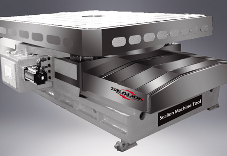
The Sauter rotary table is ideal for machines designed for complete machining. Our tables can be used for milling or grinding machines as a base for the main spindle or the workpiece carrier an allowing easy access from any position.
Our design for the B-axis rotary table focused on flexibility, precision, and robustness. This was achieved by means of:Backlash-free pre-loaded gear train

The feature of wear resistant alloy Dual-Lead Worm Gear is high mechanical e-ciency of power transmission, high indexing accuracy, and easy adjusted on the backlash.
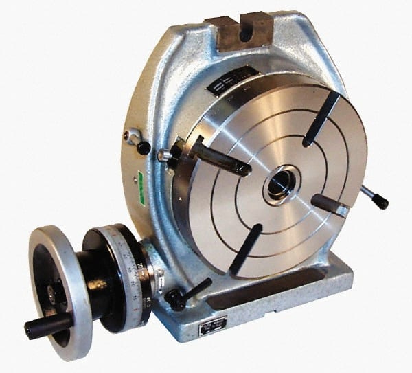
3” (75 mm) Tilting Rotary Table with a 65mm- 3 Jaw Self Centering Lathe Chuck for Milling Machine This Whole Package Includes below : - 1 Pc. 3” 75 mm Tilting Rotary table 1 Pc. of a high quality 65 mm 3 Jaw self centering Chuck 1 Pc. of a back plate which has holes in a mann more...
25mm movement on both axes on Micrometer Head 0.01 mm Circular Rotary top plate with ground slot 50mm vice fine adjustment lock with T nut Alloy Steel with Nickel Chrome Plating more...
The SIMPLEX TXE is integrated with an outside cogwheel. It is manufactured in various sizes ranging from 400 to 750 and 1100. The TS Series is manufactured by SOPAP Automation. more...
Being in the manufacturing business, every manufacture covets for automated operations with less cycle time. Fortunately, you can get it done instantly with the rotary indexing machine by Shiv Technology. This machine will reduce the cycle time and ultimately hike up the producti more...
The indexing rotary tables of the "IR" Minindex series of COLOMBO FILIPPETTI spa are cylindrical cam mechanical units that transform the uniform rotary motion of the input shaft into an indexing rotary motion of the outlet dial plate. more...
We are offering programmable rotary table. Features: 1. Model: sq-20v4 2. Angle range : 360 deg 3. Transmission ratio : 5:1 or customized as per the requirement 4. Actuator type : timer belt pulley 5. Travel guide : bearings 6. Motor : stepper motor 7. Base material : aluminum ca more...

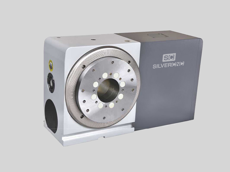
A CNC rotary table is the precision positioning accessory that can provide a reliable 4th axis or even 5th axis for modern machining centers. Utilizing a computer-controlled rotary table can turn the original 3-axis machine tools into 5-axis CNC machines, expanding the accuracy as well as decreasing the costs while performing complex machining operations at one time.
A CNC rotary table is the precision positioning accessory that can provide reliable 4 or even 5 axis cutting operation capabilities for modern machining centers. Utilizing it can turn the original 3-axis machine tools into 5-axis CNC machines, expanding the accuracy as well as decreasing the costs while performing complex machining operations.
Rotary tables typically have rigid frames and coatings, and also excellent torque capacity, which makes the small device flexible and effective for a wide variety of turning, milling, drilling, and more metalworking operations. The easy setup and seamless interface allow the operators to easily add the rotary table to fit their 4-axis or 5-axis applications. .
The working principle is similar to the basic rotary tables, which is to support the workpiece by accurately rotating the workpieces on the axis in order to locate the parts for high precision tooling. Under rapid rotation, which is driven by CNC instructions, the cutting tools of larger machine tools or machining centers can remove the material and add the feature to the products at exact intervals. On rotary tables, there are vertical and horizontal axes for various tools to perform these high-performance metalworks. To enhance the accuracy and flexibility, there are models that employ additional dividing plates and come with additonal material handling mechanisms and features.
Since 4-axis and 5-axis machining is increasingly popular today, adding the CNC rotary table as the 4th axis is an ideal solution to easily open up more complex machining options at a lower cost. Due to the arrangement, they are widely also called the 4th or 5th axis or tilt rotary. The 4th axis, which is the rotational operational direction, is added to the original three linear axes which are known as X-axis, Y-axis, Z-axis. In some cases, there are two rotational axes add to the original 3-axis machining center, achieving utmost accuracy as well as effective multiple face cutting to reach the difficult area on the surface. Rotary tables are usually mounted parallel to the ground or the bed, with the platter rotating around the vertical axis, for example with the most common vertical milling machine combination. Sometimes the machining application requires an alternative setup with the table mountet on its end so that it rotates around the horizontlal axis. Often, a tailstock is used in this configuration. Virtually all models today come with a clamping kit to mount it onto the bed of your machine tool.
The function of the high precision rotary table is also to rotate the workpiece so the cutting tool can create the contour we desired out of the workpiece. However, a rotary table with higher precision has the ability to achieve great accuracy just as its name implies. There is also a major misconception between the resolution and the accuracy.
A common example is that if a digital readout displays to four decimal places, then the high precision rotary table must also be capable of achieving the accuracy to that same value. Even though for higher accuracy to be achieved, the resolution has to also be high, but there is no guarantee that the accuracy is going to be high. The accuracy is the concept which is the difference between the actual position and the position measured by a reference measurement device. The feedback mechanism such as the rotary encoder, and the drive mechanism can influence the accuracy of the advanced rotary table.
A CNC rotary table can provide great rigidity for stable machining operations. It consists of the worktable where the metal parts are held, the rigid bearing that withstands the forces and loads during the rotation, the solid base which is used for attaching the rotary table to the machining center or other equipment, the motor, and the CNC system.
The worktable is the tooling surface where the workpieces are machined after accurate positioning. The worm gearing is the core mechanism of the table, which mesh with the steel worm which is submerged in the lubricants. Both the rigid bearings and the worm gears have large diameters. Excellent concentricity is the key to smooth operation, durability, and most importantly, accuracy. Driven by a computer and electric motor, the worktable can position the materials at exact intervals. For more flexible or critical operations, dividing plates can be added to this component.
A CNC system regulates the simultaneous 4-axis motion of the rotary table. The instructions are programmed and transmitted via CAD software, reducing the time for adjustment and monitoring by human workers.
The type and size of the electric motors utilized in can define the router accuracy as well as the efficiency of the device. Servo motor and stepper motor are two typical types that can be divided into more subtypes. The servo motor uses a closed looping variable circuit, the circuit will constantly run to keep the function. The brushes must be replaced every 2000 hours of operation in the servo motor. Compared to stepper motors, servo motors are more efficient in power consumption. On the other hand, the stepper motor has a simpler setup which are the wires that are attached to the driver. The bearing of the stepper motor is the only wearing component. However, the stepper motor consumes a great amount of energy.
There are currently several different types and models available in the industries. Each of them possess its own traits and abilities. Let us take a look at the most common ones other than standard three axis tables
The 4 axis CNC rotary table will process the workpieces by holding them in the same position while the cutting tool performs along the XYZ plane to trim away the unwanted material. In general, a 4 axis model is very versatile equipment that can be used for several different industrial processes such as engraving curved surfaces, continuous cutting, and intermittent cutting. Besides, people can also add other devices such as cam machining, blade machining, and helical grooves to the 4 axes rotary table. Such a feature is simply impossible to achieve with the machining center which has only 3 axes.
Besides the 4 axis ones, there are also 5 axis models. They have the ability to allow the workpiece to be processed automatically from five sides at one time. people usually utilized the 5 axes rotary table in the industries such as the automobile, the aerospace, and the boating industries. The reason that the 5 axes rotary table is commonly used in heavy industries is that the 5 axis machining is an important technique to be used when the components need better intricacy and quick precision. All of these have more than three axes are called the multi-axis rotary table.
The installation method of the precision rotary table can be horizontal, vertical or inverted. When installed horizontally, the workbench surface is in a flat, vertical and horizontal position. When installed vertically, a rotary table is installed so that the surface of it can run up and down. In the reverse layout, itcan be rotated upside down in a horizontal position. The location of the drive of the rotary table can depend on the mount. The drive can be placed on the back, below, on the top or on the side.
When mounted horizontally, the spinning table top drive is positioned above the table floor. When the rotary table is horizontally placed, the side-mounted drive is located on the edge of the table board. The driving mechanism of the rotary table may be manual, electrical, pneumatic, hydraulic or non-driven. For manual revolving workbenches, release the workbenches and manually spin the workbenches with the crank.
Workpieces are gathered and machined through PC and fully programmed instructions. The 5-axis simultaneous operations will be measurably more reliable than products machined via different technologies. Also, the setup is simple and provides an indistinguishable process in every production cycle, the consistency of the quality of the metal products can be ensured under critical control and precision cutting.
Since the metalwork is driven by software, the preferred frameworks can be programmed and adapted by the rotary table. Saving both the cost and the room makes themis the ideal solution for potential users who don’t want to install larger equipment and new machines which may take up a great room for a wide variety of machining applications.
Another benefit is the utmost movements can be completed precisiely and faster. There are more favorable positions, operation angles as well as accessible machining that can be achieved through the technology. The complex operations are suitable for blade, helical grooves production, and other applications required to add complex features or require critical inspection in machining processes like the manufacturing of aerospace, automotive parts, and scientific equipment.
Addding a rotational table saves time because the extra finishing jobs or other sub-operations can also be performed at one time in the machining center.
A rotary table can be used in many applications including manufacturing, inspection, and assembly. Indicators are used, for example, for assembly, manufacturing, and bottling equipment. They typically use a single item in workspaces or move relatively small layouts of items around stations for sequential work or assembly.
In automated assembly machines, the rotary tables implementation is widespread, and choosing the right mechanism is important for both improving efficiency and reducing the cost of this vital component. This guide discusses two common devices for rotating indexing and offers guidance on the right range. There are several ways to get mass mobilization when it comes to the development of rotary indexing tables. Regardless of whether the load or load in centuries of thousands of kgm2 is incredibly light. When choosing a robust rotary index solution that will match or meet your standards, there are several factors to take into account when spinning, elevating, or pushing.
When determining the influencing factors on the postitioning accuracy, the first thing to look at is the mechanical properties of the table itself. A rotary table contains six degrees of freedom. Each of these movements increases the total risk of positioning errors. Usually, a rotary table is driven by a worm gear, which is connected to the motor through a rotary encoder on the back. The position of the table can be determined by the number of pulses transmitted from the encoder to the control device.
The four main sources of error due to the semi-closed position loop are geometric errors, thermal deformation, elasticity, and wear. The sum of these errors is called angular positioning error. To greatly reduce the angular positioning error, the ideal position for installing the angle encoder is on the rotating shaft under test. The angle encoder is installed under the rotary table, and the rotary encoder is installed under the rear motor, the position loop is now considered a closed-loop system.
Precision is a relative term. About a quarter of an inch is great and will meet the accuracy of its application. Others, for example, require micron-level accuracy in measuring and indexing devices. Then, some applications fall within these extreme ranges.
The misunderstanding is that you may have used an inaccurate indexing device and made it accurate by introducing a pin or wedge locking device. These devices increase the complexity and cycle time of use, and when they are used together with a high-precision positioning device, they may cause damage and reduce accuracy.
In the actual test, by selecting specific components, motion index drive, servo rotary indexer, the measurement accuracy is as high as 5-6 microns. These are not the results approved by Motion Index Drives, but the results of customer certification. When starting and stopping large amounts of data, it is important to know how fast it takes to stop the application with large amounts of data.
In a less rigid environment or the presence of higher recoil, a faster start and stop will bring many control problems. When moving masses (whether rotating mass or linear mass), starting and stopping in a system with a backlash of several arc minutes will cause a lot of back and forth movement in the gear system. The result is a force that is difficult or even impossible to calculate. In addition, when the gear head is used in rotating applications, the farther the mass is from the center of rotation, the greater the backlash. In applications with very slow deceleration times, recoil may not be a problem.
Backlash in the positioning process is a big issue – when it comes to the beginning and stopping volumes, it"s crucial to know how quickly you need to avoid the mass of your rotary indexing table applications. In a less rigid system or where there is an increased backlash, quicker start-ups and stops can cause a lot of control issues. When shifting a mass, whether rotary or linear, starting and stopping in a system with several minutes of backlash arc will create a lot of back-and-forth motion within the gearing system. The effect is a power that can be difficult and probably hard to quantify. In comparison, as the gear head is used for rotational applications, the more the mass is from the axis of rotation, the further the backlash is magnified.
The backlash may not be a concern in systems where deceleration times are incredibly long. In the case of cam indexers, there is " Zero Backlash." The cam indexer and rotary table dynamics give an incredibly rigid, highly regulated framework. A modern cam indexer system is capable of withstanding short cycle times with stop times in milliseconds.
So you want to get the smart manufacturing going but are not sure of what to look for in rotary tables. The information provided in this section may be able to help. The primary factor is to determine the mass snapshot of inactivity. This is often overlooked when measuring a rotary table for the machine.
Another significant factor is the size of the workpiece being rotated, including how big it is and how substantial it is. You want your rotary tables to be large enough to handle enormous pieces. This is where tilling rotary tables may become handy so that the pieces can be handled without causing interior harm. They allow the quickening and decelerating of machining at appropriate rates.
The last factor is accuracy, the applications for which, for instance, pivoting a gigantic part to allow welding highlights on it where the individual stop positions can be genuinely free. On an additional note, when choosing direct drive rotary tables, factors that you should consider when selecting a rotary table for your CNC machinery include accuracy, backlash, mass moment of inertia, acceleration and deceleration, speed, and environment.
Indexing system use is commonly possible in automatic assembly machines and the right process is important for both performance maximization and cost reduction.
Cam indexers are an omnipresent tool used for several decades for rotary indexing tables. They are suitable for applications that often index the same angle and need a high degree of accuracy at a relatively low cost. To place the load, a cam indexer uses a mechanical cam. A math curve is pushed onto the cam and provides incredibly smooth and repeatable movement.
Another popular alternative is a fully programmable rotary index table. A rotary table is advantageous in two different situations. Firstly, a versatile movement pattern is important. An example is if two components are running on one computer, each of which requires different index patterns. For incredibly fast placement accompanied by a long period, another condition that matches the servo pointer is. The need to accelerate the camshaft while the cam indexing mechanism was operating before starting the output movement reduced the on-demand cam indexer. Acceleration of the camshaft is possible, but there is a delay before the movement begins. There are realistic restrictions.
With an indexing table, the output rotates as soon as the servo starts moving. This is not difficult for a continuous cam indexer or a zero-backlash servo indexer, but it can also be difficult for an on-demand cam indexer. For applications with high-speed servo indexing, smooth movements are crucial. A zero-backlash preloaded reducer can achieve this. The ideal alternative for correct positioning with high dynamic response would be the zero-backlash reel drive system.
Application parameters, like a moment of inertia, indexing angle, indexing period, and residence time, are required for each indexer style. The rotary indexing table for the application should also be sized correctly by a reputable manufacturer.

Rusach International has continued an on-going program of design and development, benefiting from years of experience in the design of special purpose Rotary Tables, Pallet Automation Systems and Metrology Products,from our Eimeldingen years. An increased product range through acquisitions and product development has enhanced the company"s work on high accuracy rotary tables. A natural progression was the introduction of retrofitting pallet automation systems in 1976. These have subsequently been supplied in "stand alone" and FMS form to suit a wide range of machining applications, also over the last few years supplying rotary and tilt CNC tables fully integrated onto slideways or as full bases for various machines.
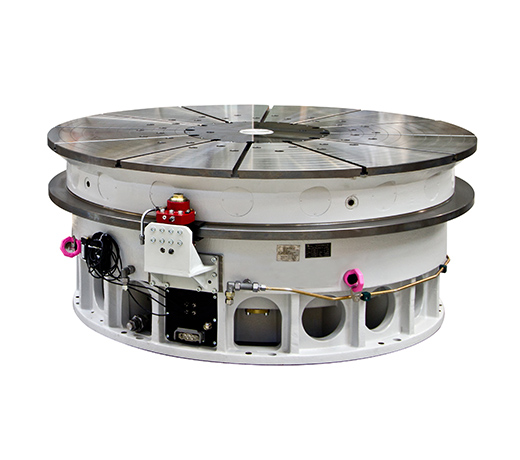
Designed and manufactured to the highest level of quality, our rotary tables feature distortion-free active clamping with roller bearings for high-resolution rotation. The rigid design and solid components make loading capacities of up to 100+ tons possible.
Rusach International has been awarded the ISO 9001:2008 Management System certificate by Perry Johnson Registrars, Inc., for the Design, Assembly and Service of Metal products for various Industries. This goal further insures that our customers receive consistent high quality products and services.

Over four decades we have accumulated a vast experience in the design and production of mechanical devices, producing well-received customized cams, automatic tool changers, and intermittent indexing drives for automation applications.


 8613371530291