
how to use a rotary table on a mill manufacturer

Years ago, before I learned CNC, I owned a Phase II 8″ horizontal/vertical rotary table that I purchased from Kap Pullen’s Getmachinetools.com store. He has them at a good price, BTW, and he’s a darned nice fellow to deal with as well as being a frequent HSM contributor. Anyway, its a nice little table, but I hadn’t done a whole lot with it for quite a while after purchasing it. As is so often the case, one day, a project landed on my doorstep and I was glad to have it.
Before I could get started, however, I had to make some accessories for it. Basically, I needed some T-Nuts to fit the table, as well as a little fixture that makes it easy to hold a plate up off the table through a hole in the center so you can machine it. The latter, what I call a “plate machining fixture”, was inspired by something similar I saw the Widgitmaster of CNCZone fame using to make Dremel clamps for his mini-router:
The Plate Maching Fixture and 3 Homemade T-Nuts. T-Nuts are easy to make: square a block to the proper dimensions, mill the side reliefs, drill, and tap. These are much smaller than the mill’s Bridgeport standard T-slots, so I made them myself and I’m using 1/4-20 bolts with them. They’re made of mild steel.
I turned the round spigot using the 4-jaw on the lathe. I’m making the fixture out of MIC-6 aluminum plate, which is pre-ground very flat on the sides. This is a 5 inch by 3 inch piece. I’ve clamped it to the rotab using my T-nuts and the regular mill clamps and step blocks. It is sitting on parallels to make sure I don’t cut into the table. You can also see how I’ve clamped the rotary table to the mill table using a big cast iron V-block I have. You can never have to many blocks with precision faces hanging around!
Having a 4-jaw chuck on your rotary table is mighty handy! Because it’s a 4-jaw, you can dial in the workpiece by adjusting the jaws until it is perfectly concentric with the table’s axis of rotation. The best way is to make an adapter plate that attaches to the back of the chuck in the same way that your lathe does so you can exchange lathe tooling with the rotab. Here is an example:
For the example, the chuck is threaded onto the adaptor plate, and then the holes in the adapter plate’s flange are used to bolt down to T-nuts on the table.
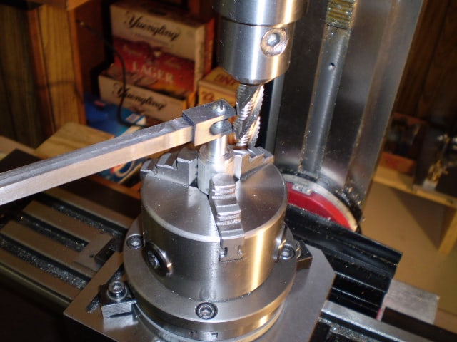
In my case, I bought a 4-jaw from Shars brand new, and simply drilled some through-holes in the chuck to mount to the table directly without an adapter plate:
First, you want to make sure your part is properly centered on the table. To do that, I clamp the table down on the mill table (no special place is needed), put my Indicol indicator holder on the mill spindle, and find some round feature on the part to indicate on. For example, on the plate milling fixture above, indicate on the round boss, or on the center hole. Spin the table and bump the part in until spinning the table doesn’t move the indicator.
Second, locate the center of rotation directly under the mill spindle. You can simply use the X and Y table handwheels to do this. Use that Indicol to indicate off of a circular feature you want centered under the spindle. Turn the indicol around on the spindle and adjust the handwheels until the indicator stays put relative to the spindle position. A Blake Coaxial indicator will make this last even simpler.
When you’re rounding partially by cranking a part around on the rotary table, it’s really easy to go a little too far and screw things up. The answer is to drill the end points to make the exact stopping point on the rotab a lot less sensitive:
Centering with a Blake indicator is really fast, but what if you don’t have a Blake, or worse, what if your mill is too small to accomodate one? Here is a nice solution I found on a German site. This fellow has made an ER collect fixture for his rotary table, and has taken care that when installed on the table, the axis of the collet is aligned with the table’s axis. He can then place a dowel or other straight pin in the collet and line up until it will go into a similarly sized collet on the spindle. Nice trick! It’s similar to how Widgitmaster showed me to align a drill chuck on a QCTP to the lathe centerline with a dowel pin held in the lathe chuck.

The rotary table is simply a round flat surface that can be rotated. What makes it interesting is that the table is driven round using a worm and wormwheel arrangement. This means that if a workpiece is mounted on the table it can be machined as it rotates.
On a rotary table the ratio between the worm and wheel is often about 40:1 on a small table but increases with the size of the table. For example a 360mm (12-inch) table might have a ratio of 120:1.
Rotary tables are calibrated round the edge in degrees and have a handle which turns the worm and which, in turn, will rotate the table by 360º divided by the ratio of the worm and wheel. For example, a 360mm (12-inch) table with a 120:1 worm and wheel will rotate by 3º per turn. The handle mechanism has a rotating dial and a Vernier so the angle, on a larger rotary table, can be measured to a few minutes.
Naturally any worm and wheel arrangement on a rotary table is likely to have some backlash. Sometimes this can be compensated for by adjusting the distance between the worm and wheel. Usually any backlash can be ignored if the movement, when machining, is always one way.
The same mechanism can sometimes be used to disengage the worm from the wormwheel. This is useful on large rotary tables because it enables the user to turn the wheel quickly to get from one position to another. (It is not possible to machine the workpiece whilst doing this.)
All rotary tables have a hole in the middle of the table. This is usually a parallel-sided hole but some, especially on smaller rotary tables it is tapered.
This hole can be used to take spigots that can be used to align the rotary table or align the workpiece on the table. Sometimes it is possible to fit a bolt through this hole using various spacers, washers, etc to hold the workpiece on the rotary table.
It is possible the get a device that has a taper on one end that is designed to fit the taper as found on some small rotary tables. The other end has a thread that is designed to fit the backplate as used on the chucks used on some lathes.
All rotary tables can be mounted in the horizontal position on the milling table. Some are designed so they can also be mounted vertically without any other hardware.
Most have slots in the base so they can be bolted to the milling table. Some do not but have a flange so that they can be clamped to the milling table.
It is possible to buy rotary tables that have the facility to tilt the table built in to them. Some even can be tilted at any angle in either or both of two planes at right angles. But all of this adds significantly to the height and weight of the rotary table.
The usefulness of being able to tilt in two planes is very limited and would probably not justify the space it would take up. But a rotary table that tilts in one plane can be useful. This setup can easily be emulated by fitting a rotary table to a tilting table.
Most rotary tables have some means of locking the table at any particular position. Very often an operation is done whilst the table is being rotated in which case the force of the cutter cancels any backlash. However when an operation such as drilling is being done at a particular point then the table should be locked.
Very often a cut needs to be made between two points at the ends of a particular arc. Usually it is not possible to make the cut in one go but several passes are needed. In this case it is useful to have two stops so each cut will start and stop at exactly the same points. This is very useful for preventing mistakes.
The fig. shows a stop. The movable part clamps to the top of the rotary table’s table. Two of these are needed. The fixed part has been fitted to the hole normally used for the locking mechanism as shown in the previous fig.
It will be noticed that the same hole on the rotary table is used for both locking and for a stop. But, of course, in practice, it will, at any one time, only be needed for one function or the other.
For milling any particular workpiece on a rotary table one has to allow for the space around the workpiece for the clamps used to hold it. For example a 200mm rotary table might hold a workpiece that had to have 120mm hole cut into it. It will be shown later how to effectively extend the diameter of a rotary table. It is often desirable to get the largest rotary table that will fit the milling machine table. However larger rotary tables can be very heavy.
With a large milling machine the practical limit is probably the largest you can lift safely. It is possible to have some sort of lifting gear but this all takes time. It is worth looking carefully before buying because for a given diameter, different makes or different methods of construction can cause a rotary table to vary dramatically in weight.
There will usually be enough space between to milling table and the cutting tool to fit a rotary table to do any required job. But there is always the height of the workpiece to consider. If other devices are to be mounted on the rotary table then the space rapidly disappears.
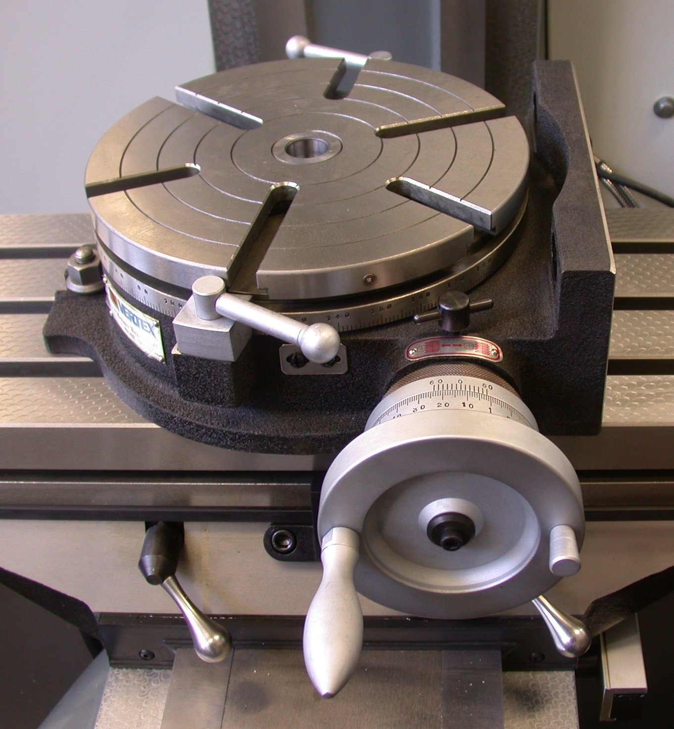
Most rotary table are set up as shown above to be rotated by a certain number of degrees. This is done using the calibrations on the table marked in degrees.
If it is necessary, when using a rotary table to divide a circle into a number of equal sectors then it is necessary to divide 360º by the number of sectors required. On a small rotary table, the table might only be calibrated to 5°. On larger ones they might be calibrated to individual degrees round the edge but will have a vernier arrangement on the handle so they can be set to a certain number of minutes. This gives us the angle between the sectors. Each time we move from one sector to the next we have to add the angle per sector onto the last angle. For any but the simplest numbers, the chances of getting this right are not great.
It is possible to have dividing plates fitted to a rotating table, as shown above, but this is unusual. But since dividing plates are always fitted to dividing heads these will be covered under dividing heads.
It is quite common to need to be able to divide a circle into so many parts. With dividing plates this is easy and is covered elsewhere. for a rotary table using just degrees and minutes a circle can be divided by one of the following methods.
A calculate the angle in your head or using a calculator for the origin for each sector and write them down. Most simple calculators will give decimal angles whereas the rotary table is marked in degrees and minutes.
B use a spreadsheet to produce a list of angles. These will probably be decimal angles. But is then quite easy to turn decimal degrees into degrees and minutes.
C Use tables showing the angles for each position for a circle divided up to 200 sectors can be found in Appendix C. These are in degrees and minutes.
D use the table for the first 200 sectors that can be found in “Tables for [the] Cooke Optical Dividing Head” published by Cooke, Troughton and Simms.

rotary filing—that is, running a circular cutter withfile-like teeth in the headstock of alathe.Rotary filling and later,true milling were developed to reduce time and effort
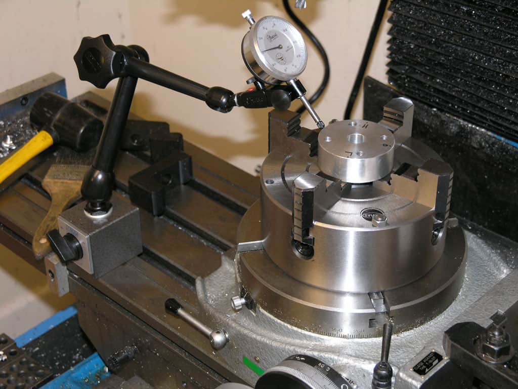
Here is what I like to use as a test indicator holder. It can allow you to indicate in something without removing the tool. They have several options for in spindle or spindle nose clamp styles. eBay does have some cheaper import version that work ok, but once you have use the Indicol quality, there is a big difference. You will need to buy the test indicator as a seperate item. There are a lot on the market. I have had my B&S(brown and Sharp) "Best Test" indicator for almost 30 years and one repair. Reasonably rugged and very reliable. Sticky indicators like some imports do you no good. If the needle pointer does not move, it is inviting a false sense of security.
The whole premise is to use the spindle bearings to sweep an indicator around the surface you wish to align it to. It is much easier in concert with a DRO, but dials will get you there too.
As long as you do not move the table, you could indicate the part in by knocking it around until it sets in the same location. You could also spin the table itself and knock the part around to find its true center on the rotation of the table bearings. Some of the cheaper import rotary tables may not have the spindle bore as reliably on center as what they will rotate on their shaft.
The same indicator setup can check for spindle tram also. This will need to be checked periodically anyways to verify the spindle is perpendicular to the table surface. If the head is tilted and you indicate in a feature. If the point that it is indicated in at changes in height, so to will the location of the features you intend to machine in relation to that reference. The longer the tool bit is away from the indicated origin, the further off location the new feature will be. Where this is seen is when the part is indicated in at one level, but the distance between the spindle and work needs more room for the tool. So when the table drops away, the point of origin in relation the spindle center (being at an angle) is out lost in space now. The new feature(s) can be found way off location even though the table was moved correctly during the setup. Best advice is to keep this in mind if the knee or head will be moved in a Z axis, always check the tram first. Especially after a crash, broken cutter or large unexpected force at the cutter.
The same holds true for vises parallel to an axis. For critical work, always check the solid jaw for axis alignment. If it is at an angle and a feature is indicated in on one end of the jaws, it might not be at the other end. More or less exponentially to the angle it is off over XX distance from the origin.
Main objective here is to use as much of the machines built in geometry to maintain pure geometry on the part as the machines is capable of. A test indicator is the best way to obtain this level of precision.

A rotary table is a precision work positioning device used in metalworking. It enables the operator to drill or cut work at exact intervals around a fixed (usually horizontal or vertical) axis. Some rotary tables allow the use of index plates for indexing operations, and some can also be fitted with dividing plates that enable regular work positioning at divisions for which indexing plates are not available. A rotary fixture used in this fashion is more appropriately called a dividing head (indexing head).
The table shown is a manually operated type. Powered tables under the control of CNC machines are now available, and provide a fourth axis to CNC milling machines. Rotary tables are made with a solid base, which has provision for clamping onto another table or fixture. The actual table is a precision-machined disc to which the work piece is clamped (T slots are generally provided for this purpose). This disc can rotate freely, for indexing, or under the control of a worm (handwheel), with the worm wheel portion being made part of the actual table. High precision tables are driven by backlash compensating duplex worms.
The ratio between worm and table is generally 40:1, 72:1 or 90:1 but may be any ratio that can be easily divided exactly into 360°. This is for ease of use when indexing plates are available. A graduated dial and, often, a vernier scale enable the operator to position the table, and thus the work affixed to it with great accuracy.
Rotary tables are most commonly mounted "flat", with the table rotating around a vertical axis, in the same plane as the cutter of a vertical milling machine. An alternate setup is to mount the rotary table on its end (or mount it "flat" on a 90° angle plate), so that it rotates about a horizontal axis. In this configuration a tailstock can also be used, thus holding the workpiece "between centers."
With the table mounted on a secondary table, the workpiece is accurately centered on the rotary table"s axis, which in turn is centered on the cutting tool"s axis. All three axes are thus coaxial. From this point, the secondary table can be offset in either the X or Y direction to set the cutter the desired distance from the workpiece"s center. This allows concentric machining operations on the workpiece. Placing the workpiece eccentrically a set distance from the center permits more complex curves to be cut. As with other setups on a vertical mill, the milling operation can be either drilling a series of concentric, and possibly equidistant holes, or face or end milling either circular or semicircular shapes and contours.
To create large-diameter holes, via milling in a circular toolpath, on small milling machines that don"t have the power to drive large twist drills (>0.500"/>13 mm)
with the addition of a compound table on top of the rotary table, the user can move the center of rotation to anywhere on the part being cut. This enables an arc to be cut at any place on the part.
Additionally, if converted to stepper motor operation, with a CNC milling machine and a tailstock, a rotary table allows many parts to be made on a mill that otherwise would require a lathe.
Rotary tables have many applications, including being used in the manufacture and inspection process of important elements in aerospace, automation and scientific industries. The use of rotary tables stretches as far as the film and animation industry, being used to obtain accuracy and precision in filming and photography.
For cancellations, you can reach us out at +91 9319511441 / support@chandcompany.in or request for Order cancellation from the My Orders section in your My Account option.
You have up to 48 hours from the time of placing your order to cancel your order. Once the order is cancelled, the amount will be reimbursed for all ‘PREPAID ORDERS’
Order can be cancelled before the shipment of the order has been processed i.e 48 hours after placing the order. CHAND COMPANY can cancel the order for various reasons such as:-
Unavailability of products – in exceptional cases, is a product runs “out of stock” with us at our warehouse, the product will be cancelled and all the necessary information will be given beforehand to the customer about the unavailability of the order and order cancellation
Chand Company and its logistic partners take due care in delivering the product(s) in the best condition, however, in the rare occasions of damaged goods being received or any discrepancies with the products received, you can reach us out with the images of the damaged product along with the packaging pictures at support@chandcompany.in and +919319511441 within 48 hours of receiving the material, to resolve your issue.
All products have a Warranty against Manufacturing defects IF STATED OTHERWISE IN THE ITEM DESCRIPTION, which can be easily identified when the product is put to use. In case of any manufacturing defect in the product, the customer needs to inform us within 5 days of receiving the order. The return intimation will then be taken into consideration and will be followed up with the customer, ensuring a proper solution to the customer and change the material with the same product, if need be. Please note that the products can not be interchanged with any other item even if the return has been accepted.
In case of any manufacturing defect in the product, the customer needs to inform us at support@chandcompany.in or +919319511441 within 5 days of receiving the material. Our executive team will then get in touch with the customer and work their best to solve the issue as soon as they can with utmost diligence and precision. If the product, in a perfect working condition, is deemed faulty and irreparable, then the customer will be provided with a new piece once the old material has been received by us
In case the product is delivered damaged, the customer needs to inform us at support@chandcompany.in or +919319511441 within 48 hours of receiving the material along with the pictures of the damaged item and the packaging of the product. The customer is then entitled to send us the material back and a proper inspection will be made by our engineers to infer the reason for the damage. If the item is then informed by our engineers to be damaged in transit. the customer will be provided with a fresh new piece within 2-3 working days.
All items must be returned in their original condition, with packaging and boxes intact, user manual, Calibration / Inspection certificates and original accessories in it
In order to return the product, the customer has to send the product to us through the India Post only. Once the product is received by us, then the courier charges will be reversed to the customer if a manufacturing defect has been found by our team after a thorough inspection
The customer needs to pack the product with brand packaging. keep the invoice inside the box and courier it to us at CHAND COMPANY, 4772, HAUZ QAZI DELHI-06.
After a thorough inspection of the product, the customer will be informed about the situation of his product and also if the return is possible on the product or not. Our Quality inspection team will do their best to reach maximum customer satisfaction and help them in all ways possible.
In case, after receiving the material if we find any discrepancy by our Quality check team, a new product will be shipped to the customer free of cost and will reach the customer in 3-4 working days.
Products marked as “non-refundable” on the item description page cannot be returned under any circumstance. If any problem against manufacturing is observed in the product, then our executive team will look into the matter and get it resolved for the customer"s satisfaction.
After receiving the required information for a refund, a refund will be processed in 2 business days and the same will reflect in the customer account in another 2-4 business days
Prop 65 Warning(s)Many metalworking products contain chemicals or metals included in the latest Prop 65 warning. Exposure may cause cancer and reproductive harm. KBC is currently gathering required California Prop 65 warnings for our customers. For more information go to www.P65Warnings.ca.gov

Whether you use mills, presses or lathes, machine tools are often only as useful as the accessories that come with them. Take care of repair tasks and add extra functionality with the machine tools accessories at Alibaba.com. If you need new milling machine rotary table or are seeking to replenish your component stocks, our wholesale store is the ideal place to look. We stock accessories for every type of machine tool, with multiple options in most cases. So add resilience to your operations and be ready for any production challenge with the machine tools accessories in our store.
Machine tools come in all shapes and sizes, and so do the accessories that make them tick. For instance, CNC and manual lathes can be customized with jaw chucks, shanks, woodworking knives, drill chucks, rotary chucks, clamps, and turning tools. Add brushes and sanding discs, and turn your machine tool into a multi-purpose machining center. Add a range of cutting tools to milling machines, pick the right drum sanders for your drills, or add a lathe dog to make turning much easier. There are accessories for hydraulic presses, add-ons like drag chains, and many other machine tools accessories. And if you need replacement milling machine rotary table, Alibaba has everything you need.
Our machine tools catalog is packed with accessories. Search the listings for your preferred tool and zero in on accessories that can enhance its functionality. From control handles to tool holders, thread holders and saw blades, the whole panorama of machine tools accessories is here and ready to order. There"s no better way to add extra stocks and renovate machinery when the time comes. When new milling machine rotary table are required, head to the Alibaba wholesale store and give your machinery a new lease of life.

A rotary table used in conjunction with a mill allows a machinist to produce virtually any part they can design. Sherline’s rotary table is a precision piece of equipment that has been designed to work with their vertical milling machines, however, it can be used on any mill whenever the small 4-inch size would be an advantage. The only limits are size, not complexity.
The table is 2″ high and 4″ (100mm) in diameter. The main components have been machined from solid bar stock steel, and the complete unit weighs seven pounds. The table has been engraved with a laser, giving sharp and precise lines every 5°, numbered every 15°. These lines are calibrated with the 72-tooth worm gear that is driven by the handwheel. The handwheel is divided into 50 parts, making each line on the handwheel 1/10°. This allows a circle to be divided into 3600 increments without interpolation. Seventy-two revolutions of the handwheel rotate the table one revolution.
The rotary tables can hold more weight when they are not under a continuous load. Click on the Video tab above to see examples of different weights and uses for our rotary tables.
The table T-slots are identical to those used on the Sherline mill and lathe, making the vast line of Sherline tooling available for use with this product. Two hold-down clamps and T-nuts are provided with the table. Also included is an adapter that allows Sherline’s 3- and 4-jaw chucks to be screwed directly to the rotary table. An optional right-angle attachment is available (P/N 3701) to mount the table in the vertical position to further increase its versatility. With the table mounted vertically, an optional adjustable right-angle tailstock (P/N 3702) can be mounted to the mill table. It is used to support and stabilize the other end of long work held in a chuck or otherwise attached to the rotary table.

The work table is graduated 360 degrees around its circumference and is driven by a precision Worm and Gear providing a 90:1 reduction ratio. One turn of the Handle moves the Table through 4 degrees. ...
While the conventional drives are dependent on an external controller unit, for the compact drives no additional controller is needed. The complete electrical parts, including the drive controller and encoder, are integrated ...
... Turntables, which can be spun freely by hand are ideal for mounting and rotation of test specimens, cameras, transducers, sensors, and mirrors. They are a convenient, accurate method of quickly positioning or rotating ...
The Siegmund height adjustable rotating table provides an ergonomic and space saving solution. The work top height is infinitely variable and can be fixed in position by a side locking lever.
The Siegmund height adjustable rotating table provides an ergonomic and space saving solution. The work top height is infinitely variable and can be fixed in position by a side locking lever.
This low profile turntable / floor height turntable is less than 1" high and can be loaded by a hand pallet truck. By rotating the load the operator ...
This large non-powered turn table is for those big positioning jobs where heavy loads must be rotated on a regular basis. This turn table has a capacity up to 7,000 lbs. and a platform size of 4 feet ...
The KESSLER Table line includes single-axis rotary tables and dual-axis rotary tilt tables. It incorporates the renowned KESSLER know-how for superior ...
... sprinkling with powdered sugar, cocoa powder, chocolate sprinkles, nuts or almonds, chocolate beans or pine nuts. whether turntables for manual or fully automatic sprinkling powder drums series PTR, the ...
Model LPTG is a heavy duty turntable featuring a 1912 gravity roller top and concave transition sections (2 included) that can be used in a pass thru conveyor line. The transition section can be reconfigured to make 90° ...
S35 Manual Turntables enable workers to easily rotate heavy loads. The heavy-duty design of these manual industrial turntables is specially engineered to withstand the ...
The Heavy-Duty Manual Turntable maximizes workspace and minimizes wasteful motion. Bench top turntables allow workers to stay in one position and rotate items for access ...
With DirectIndustry you can: Find the product, subcontractor or service provider you need | Find a nearby distributor or reseller| Contact the manufacturer to get a quote or a price | Examine product characteristics and technical specifications for major brands | View PDF catalogues and other online documentation

PO Box, APO/FPO, Africa, Alaska/Hawaii, Albania, American Samoa, Andorra, Armenia, Azerbaijan Republic, Bangladesh, Bhutan, Bosnia and Herzegovina, Brazil, Brunei Darussalam, Cambodia, Central America and Caribbean, China, Cook Islands, Ecuador, Falkland Islands (Islas Malvinas), Fiji, French Guiana, French Polynesia, Greenland, Guam, Jordan, Kazakhstan, Kiribati, Kyrgyzstan, Liechtenstein, Macedonia, Marshall Islands, Micronesia, Moldova, Monaco, Mongolia, Montenegro, Nauru, Nepal, New Caledonia, Niue, Norway, Pakistan, Palau, Papua New Guinea, Russian Federation, San Marino, Solomon Islands, Svalbard and Jan Mayen, Taiwan, Tajikistan, Tonga, Turkmenistan, Tuvalu, Ukraine, Uzbekistan, Vanuatu, Vatican City State, Venezuela, Vietnam, Wallis and Futuna, Western Samoa, Yemen


 8613371530291