
how to use a rotary table on a milling machine manufacturer

Years ago, before I learned CNC, I owned a Phase II 8″ horizontal/vertical rotary table that I purchased from Kap Pullen’s Getmachinetools.com store. He has them at a good price, BTW, and he’s a darned nice fellow to deal with as well as being a frequent HSM contributor. Anyway, its a nice little table, but I hadn’t done a whole lot with it for quite a while after purchasing it. As is so often the case, one day, a project landed on my doorstep and I was glad to have it.
Before I could get started, however, I had to make some accessories for it. Basically, I needed some T-Nuts to fit the table, as well as a little fixture that makes it easy to hold a plate up off the table through a hole in the center so you can machine it. The latter, what I call a “plate machining fixture”, was inspired by something similar I saw the Widgitmaster of CNCZone fame using to make Dremel clamps for his mini-router:
The Plate Maching Fixture and 3 Homemade T-Nuts. T-Nuts are easy to make: square a block to the proper dimensions, mill the side reliefs, drill, and tap. These are much smaller than the mill’s Bridgeport standard T-slots, so I made them myself and I’m using 1/4-20 bolts with them. They’re made of mild steel.
I turned the round spigot using the 4-jaw on the lathe. I’m making the fixture out of MIC-6 aluminum plate, which is pre-ground very flat on the sides. This is a 5 inch by 3 inch piece. I’ve clamped it to the rotab using my T-nuts and the regular mill clamps and step blocks. It is sitting on parallels to make sure I don’t cut into the table. You can also see how I’ve clamped the rotary table to the mill table using a big cast iron V-block I have. You can never have to many blocks with precision faces hanging around!
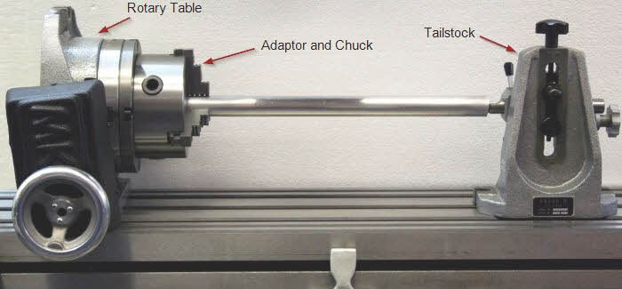
Having a 4-jaw chuck on your rotary table is mighty handy! Because it’s a 4-jaw, you can dial in the workpiece by adjusting the jaws until it is perfectly concentric with the table’s axis of rotation. The best way is to make an adapter plate that attaches to the back of the chuck in the same way that your lathe does so you can exchange lathe tooling with the rotab. Here is an example:
For the example, the chuck is threaded onto the adaptor plate, and then the holes in the adapter plate’s flange are used to bolt down to T-nuts on the table.
In my case, I bought a 4-jaw from Shars brand new, and simply drilled some through-holes in the chuck to mount to the table directly without an adapter plate:
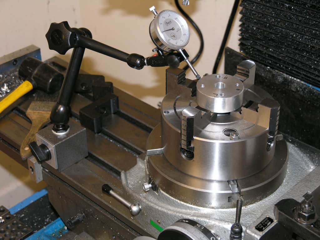
First, you want to make sure your part is properly centered on the table. To do that, I clamp the table down on the mill table (no special place is needed), put my Indicol indicator holder on the mill spindle, and find some round feature on the part to indicate on. For example, on the plate milling fixture above, indicate on the round boss, or on the center hole. Spin the table and bump the part in until spinning the table doesn’t move the indicator.
Second, locate the center of rotation directly under the mill spindle. You can simply use the X and Y table handwheels to do this. Use that Indicol to indicate off of a circular feature you want centered under the spindle. Turn the indicol around on the spindle and adjust the handwheels until the indicator stays put relative to the spindle position. A Blake Coaxial indicator will make this last even simpler.
When you’re rounding partially by cranking a part around on the rotary table, it’s really easy to go a little too far and screw things up. The answer is to drill the end points to make the exact stopping point on the rotab a lot less sensitive:
Centering with a Blake indicator is really fast, but what if you don’t have a Blake, or worse, what if your mill is too small to accomodate one? Here is a nice solution I found on a German site. This fellow has made an ER collect fixture for his rotary table, and has taken care that when installed on the table, the axis of the collet is aligned with the table’s axis. He can then place a dowel or other straight pin in the collet and line up until it will go into a similarly sized collet on the spindle. Nice trick! It’s similar to how Widgitmaster showed me to align a drill chuck on a QCTP to the lathe centerline with a dowel pin held in the lathe chuck.

rotary filing—that is, running a circular cutter withfile-like teeth in the headstock of alathe.Rotary filling and later,true milling were developed to reduce time and effort

I usually get a good many arguments started about rotary table setups. I worked in a large forge die shop, and I still do the setups the way we were shown in that shop. Probably 95% of the time you used a rotary table on a rotary head milling machine, so getting stuff on center was step #1.
The first thing to be pointed out is that the center hole and OD of the table aren"t necessarily on the axis of rotation. Easy to check, take the worm out of engagement and pull the table around by hand with an indicator zeroed on the center hole. Just like indicating a part in a four jaw.
If it is on center, that"s great. If not, you can eyeball your part on center and lightly clamp while you indicate it in by pulling the table around by hand and tapping it. If you don"t have a concentric hole or OD to use an indicator on, a center punch mark and a pump center can be used.
Once the part is on the center of the rotary tables axis, it"s a simple matter to center it under the machine spindle by locking the table and rotating the machine spindle and indicating like you would normally.

The rotary table is simply a round flat surface that can be rotated. What makes it interesting is that the table is driven round using a worm and wormwheel arrangement. This means that if a workpiece is mounted on the table it can be machined as it rotates.
On a rotary table the ratio between the worm and wheel is often about 40:1 on a small table but increases with the size of the table. For example a 360mm (12-inch) table might have a ratio of 120:1.
Rotary tables are calibrated round the edge in degrees and have a handle which turns the worm and which, in turn, will rotate the table by 360º divided by the ratio of the worm and wheel. For example, a 360mm (12-inch) table with a 120:1 worm and wheel will rotate by 3º per turn. The handle mechanism has a rotating dial and a Vernier so the angle, on a larger rotary table, can be measured to a few minutes.
Naturally any worm and wheel arrangement on a rotary table is likely to have some backlash. Sometimes this can be compensated for by adjusting the distance between the worm and wheel. Usually any backlash can be ignored if the movement, when machining, is always one way.
The same mechanism can sometimes be used to disengage the worm from the wormwheel. This is useful on large rotary tables because it enables the user to turn the wheel quickly to get from one position to another. (It is not possible to machine the workpiece whilst doing this.)
All rotary tables have a hole in the middle of the table. This is usually a parallel-sided hole but some, especially on smaller rotary tables it is tapered.
This hole can be used to take spigots that can be used to align the rotary table or align the workpiece on the table. Sometimes it is possible to fit a bolt through this hole using various spacers, washers, etc to hold the workpiece on the rotary table.
It is possible the get a device that has a taper on one end that is designed to fit the taper as found on some small rotary tables. The other end has a thread that is designed to fit the backplate as used on the chucks used on some lathes.
All rotary tables can be mounted in the horizontal position on the milling table. Some are designed so they can also be mounted vertically without any other hardware.
Most have slots in the base so they can be bolted to the milling table. Some do not but have a flange so that they can be clamped to the milling table.
It is possible to buy rotary tables that have the facility to tilt the table built in to them. Some even can be tilted at any angle in either or both of two planes at right angles. But all of this adds significantly to the height and weight of the rotary table.
The usefulness of being able to tilt in two planes is very limited and would probably not justify the space it would take up. But a rotary table that tilts in one plane can be useful. This setup can easily be emulated by fitting a rotary table to a tilting table.
Most rotary tables have some means of locking the table at any particular position. Very often an operation is done whilst the table is being rotated in which case the force of the cutter cancels any backlash. However when an operation such as drilling is being done at a particular point then the table should be locked.
Very often a cut needs to be made between two points at the ends of a particular arc. Usually it is not possible to make the cut in one go but several passes are needed. In this case it is useful to have two stops so each cut will start and stop at exactly the same points. This is very useful for preventing mistakes.
The fig. shows a stop. The movable part clamps to the top of the rotary table’s table. Two of these are needed. The fixed part has been fitted to the hole normally used for the locking mechanism as shown in the previous fig.
It will be noticed that the same hole on the rotary table is used for both locking and for a stop. But, of course, in practice, it will, at any one time, only be needed for one function or the other.
For milling any particular workpiece on a rotary table one has to allow for the space around the workpiece for the clamps used to hold it. For example a 200mm rotary table might hold a workpiece that had to have 120mm hole cut into it. It will be shown later how to effectively extend the diameter of a rotary table. It is often desirable to get the largest rotary table that will fit the milling machine table. However larger rotary tables can be very heavy.
With a large milling machine the practical limit is probably the largest you can lift safely. It is possible to have some sort of lifting gear but this all takes time. It is worth looking carefully before buying because for a given diameter, different makes or different methods of construction can cause a rotary table to vary dramatically in weight.
There will usually be enough space between to milling table and the cutting tool to fit a rotary table to do any required job. But there is always the height of the workpiece to consider. If other devices are to be mounted on the rotary table then the space rapidly disappears.
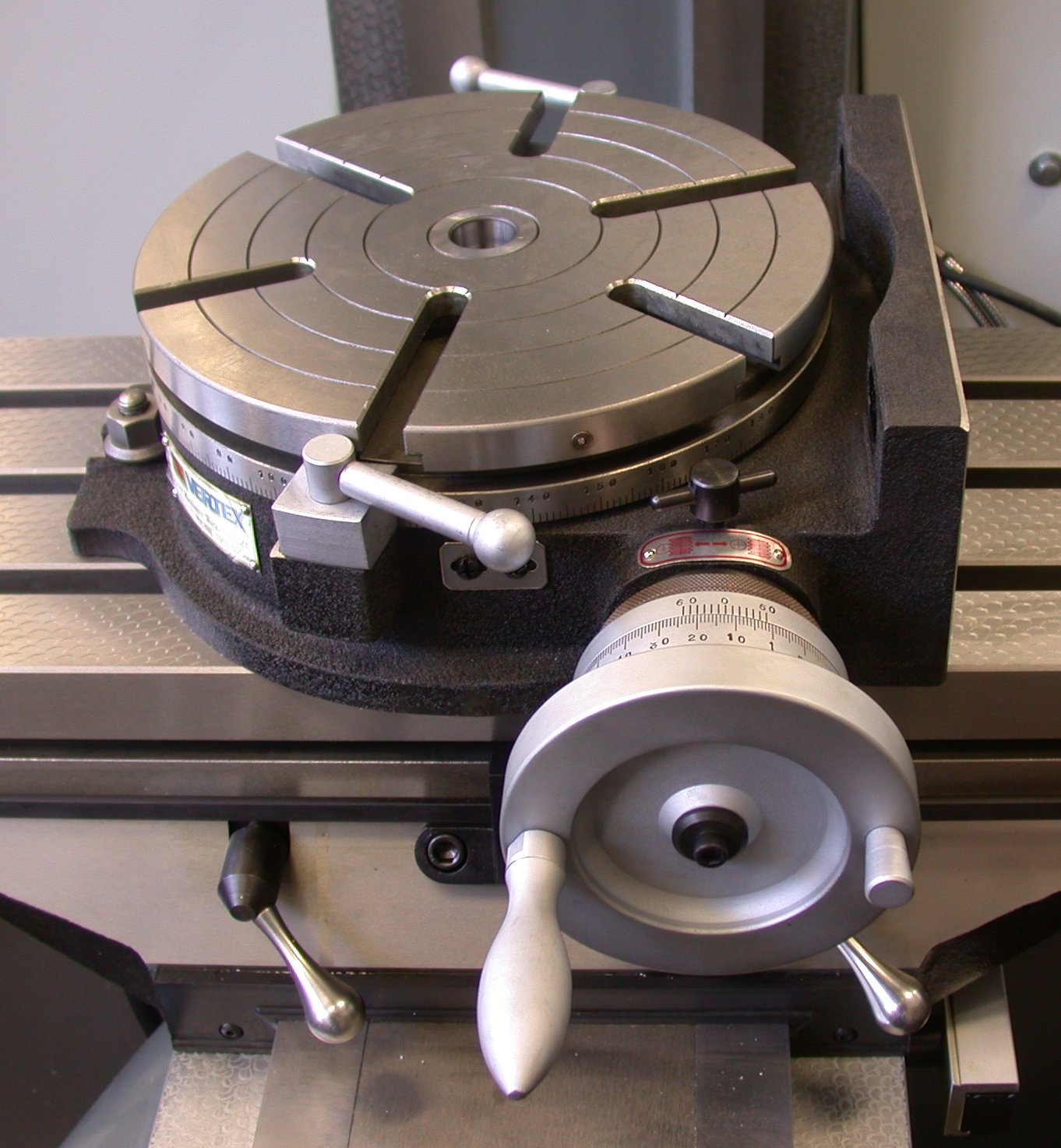
Most rotary table are set up as shown above to be rotated by a certain number of degrees. This is done using the calibrations on the table marked in degrees.
If it is necessary, when using a rotary table to divide a circle into a number of equal sectors then it is necessary to divide 360º by the number of sectors required. On a small rotary table, the table might only be calibrated to 5°. On larger ones they might be calibrated to individual degrees round the edge but will have a vernier arrangement on the handle so they can be set to a certain number of minutes. This gives us the angle between the sectors. Each time we move from one sector to the next we have to add the angle per sector onto the last angle. For any but the simplest numbers, the chances of getting this right are not great.
It is possible to have dividing plates fitted to a rotating table, as shown above, but this is unusual. But since dividing plates are always fitted to dividing heads these will be covered under dividing heads.
It is quite common to need to be able to divide a circle into so many parts. With dividing plates this is easy and is covered elsewhere. for a rotary table using just degrees and minutes a circle can be divided by one of the following methods.
A calculate the angle in your head or using a calculator for the origin for each sector and write them down. Most simple calculators will give decimal angles whereas the rotary table is marked in degrees and minutes.
B use a spreadsheet to produce a list of angles. These will probably be decimal angles. But is then quite easy to turn decimal degrees into degrees and minutes.
C Use tables showing the angles for each position for a circle divided up to 200 sectors can be found in Appendix C. These are in degrees and minutes.
D use the table for the first 200 sectors that can be found in “Tables for [the] Cooke Optical Dividing Head” published by Cooke, Troughton and Simms.
Run the quill down and touch the sharpie to the rotary table table and by moving the mill table (cross feed) draw a line that will be parallel to the work.....
Now, use an indicator to final align the edge of the plate to be true to the machine ........Do this by rotating the table....Be sure to make all corrections by turning hand wheel in the direction that you will
If you have a moveable degree pointer for the table also set it to zero (most have some adjustment here)....If that is not available on your table make a simple sheet steel pointer plate that is just plain(no pointer.
Move to and cut features as needed...be sure to account for backlash in the table worm...(The starting point for the rotary cuts need to be positioned by moving in the direction you moved to set the plate to zero.)...

The crosslide table all depends on where the slides are...above the point of rotation or below. Below is pretty much the cheap line and really is redundant putting on a mill as you already have 2 axis there. Now, slides above the pivot point allows you to position your part any where on table, center it above the pivot using the slides (U & V axis?) all with out tapping it about like a rotary table w/o slides. Also, you can then offset a part to center a desired radius elsewhere...example: you need to mill a 4" square hole with r.535 in corners. On a plain rotary table you would need to relocate the part for each corner...with topslides you use the U & V axis to position the center of R.535 over the pivot and turn the corner. This works for all kinds of stuff...milling angles off the X&Y that come tang to a rad, or even milling multiple circles or countours on a single pc w/o remounting and locating the pc. Think of 3 O-ring grooves on a hydraulic cover, or the snowman shape in a gearpump hsg. These can get confusing as now you have a manual machine with C,U,V,W,X,Y,&Z axis....wow.
The best has to be Advance 15X15. I know this unit cost $4500 15 years ago.Troyke made them also but I don"t know of others. Palmgren I thought made the bottom slide type. Alas, the 2axis CNC retros can outrun it and these are rapidly becoming dinosaurs.
Whether you use mills, presses or lathes, machine tools are often only as useful as the accessories that come with them. Take care of repair tasks and add extra functionality with the machine tools accessories at Alibaba.com. If you need new milling machine rotary table or are seeking to replenish your component stocks, our wholesale store is the ideal place to look. We stock accessories for every type of machine tool, with multiple options in most cases. So add resilience to your operations and be ready for any production challenge with the machine tools accessories in our store.
Machine tools come in all shapes and sizes, and so do the accessories that make them tick. For instance, CNC and manual lathes can be customized with jaw chucks, shanks, woodworking knives, drill chucks, rotary chucks, clamps, and turning tools. Add brushes and sanding discs, and turn your machine tool into a multi-purpose machining center. Add a range of cutting tools to milling machines, pick the right drum sanders for your drills, or add a lathe dog to make turning much easier. There are accessories for hydraulic presses, add-ons like drag chains, and many other machine tools accessories. And if you need replacement milling machine rotary table, Alibaba has everything you need.
Our machine tools catalog is packed with accessories. Search the listings for your preferred tool and zero in on accessories that can enhance its functionality. From control handles to tool holders, thread holders and saw blades, the whole panorama of machine tools accessories is here and ready to order. There"s no better way to add extra stocks and renovate machinery when the time comes. When new milling machine rotary table are required, head to the Alibaba wholesale store and give your machinery a new lease of life.

Prop 65 Warning(s)Many metalworking products contain chemicals or metals included in the latest Prop 65 warning. Exposure may cause cancer and reproductive harm. KBC is currently gathering required California Prop 65 warnings for our customers. For more information go to www.P65Warnings.ca.gov
Quality Caste Iron Rotary table Diameter 4" (100 mm) horizontal / vertical clamping unit Height when horizontally laid is only 53 mm Table calibrated 0-360 degrees table 36-1 ratio, which means one turn of the handle rotate 10 degree of the table. Enable the user to drill or cut any work at an exact interval around a fixed axis (generally vertical or horizontal) Suitable M6 clamp kit for this rotary table this will fit both the horizontal & tilting model of our 3" (75 mm) & 4" (100 mm) rotary - 4 slots table This set includes following: 2 x step blocks 2 x tee bolts with flanged nut M6 thread 2 x clamps bolt length: 55 mm overall & bolt thread M6

A CNC rotary table is the precision positioning accessory that can provide a reliable 4th axis or even 5th axis for modern machining centers. Utilizing a computer-controlled rotary table can turn the original 3-axis machine tools into 5-axis CNC machines, expanding the accuracy as well as decreasing the costs while performing complex machining operations at one time.
A CNC rotary table is the precision positioning accessory that can provide reliable 4 or even 5 axis cutting operation capabilities for modern machining centers. Utilizing it can turn the original 3-axis machine tools into 5-axis CNC machines, expanding the accuracy as well as decreasing the costs while performing complex machining operations.
Rotary tables typically have rigid frames and coatings, and also excellent torque capacity, which makes the small device flexible and effective for a wide variety of turning, milling, drilling, and more metalworking operations. The easy setup and seamless interface allow the operators to easily add the rotary table to fit their 4-axis or 5-axis applications. .
The working principle is similar to the basic rotary tables, which is to support the workpiece by accurately rotating the workpieces on the axis in order to locate the parts for high precision tooling. Under rapid rotation, which is driven by CNC instructions, the cutting tools of larger machine tools or machining centers can remove the material and add the feature to the products at exact intervals. On rotary tables, there are vertical and horizontal axes for various tools to perform these high-performance metalworks. To enhance the accuracy and flexibility, there are models that employ additional dividing plates and come with additonal material handling mechanisms and features.
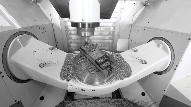
Since 4-axis and 5-axis machining is increasingly popular today, adding the CNC rotary table as the 4th axis is an ideal solution to easily open up more complex machining options at a lower cost. Due to the arrangement, they are widely also called the 4th or 5th axis or tilt rotary. The 4th axis, which is the rotational operational direction, is added to the original three linear axes which are known as X-axis, Y-axis, Z-axis. In some cases, there are two rotational axes add to the original 3-axis machining center, achieving utmost accuracy as well as effective multiple face cutting to reach the difficult area on the surface. Rotary tables are usually mounted parallel to the ground or the bed, with the platter rotating around the vertical axis, for example with the most common vertical milling machine combination. Sometimes the machining application requires an alternative setup with the table mountet on its end so that it rotates around the horizontlal axis. Often, a tailstock is used in this configuration. Virtually all models today come with a clamping kit to mount it onto the bed of your machine tool.
The function of the high precision rotary table is also to rotate the workpiece so the cutting tool can create the contour we desired out of the workpiece. However, a rotary table with higher precision has the ability to achieve great accuracy just as its name implies. There is also a major misconception between the resolution and the accuracy.
A common example is that if a digital readout displays to four decimal places, then the high precision rotary table must also be capable of achieving the accuracy to that same value. Even though for higher accuracy to be achieved, the resolution has to also be high, but there is no guarantee that the accuracy is going to be high. The accuracy is the concept which is the difference between the actual position and the position measured by a reference measurement device. The feedback mechanism such as the rotary encoder, and the drive mechanism can influence the accuracy of the advanced rotary table.
A CNC rotary table can provide great rigidity for stable machining operations. It consists of the worktable where the metal parts are held, the rigid bearing that withstands the forces and loads during the rotation, the solid base which is used for attaching the rotary table to the machining center or other equipment, the motor, and the CNC system.
The worktable is the tooling surface where the workpieces are machined after accurate positioning. The worm gearing is the core mechanism of the table, which mesh with the steel worm which is submerged in the lubricants. Both the rigid bearings and the worm gears have large diameters. Excellent concentricity is the key to smooth operation, durability, and most importantly, accuracy. Driven by a computer and electric motor, the worktable can position the materials at exact intervals. For more flexible or critical operations, dividing plates can be added to this component.
A CNC system regulates the simultaneous 4-axis motion of the rotary table. The instructions are programmed and transmitted via CAD software, reducing the time for adjustment and monitoring by human workers.
The type and size of the electric motors utilized in can define the router accuracy as well as the efficiency of the device. Servo motor and stepper motor are two typical types that can be divided into more subtypes. The servo motor uses a closed looping variable circuit, the circuit will constantly run to keep the function. The brushes must be replaced every 2000 hours of operation in the servo motor. Compared to stepper motors, servo motors are more efficient in power consumption. On the other hand, the stepper motor has a simpler setup which are the wires that are attached to the driver. The bearing of the stepper motor is the only wearing component. However, the stepper motor consumes a great amount of energy.
There are currently several different types and models available in the industries. Each of them possess its own traits and abilities. Let us take a look at the most common ones other than standard three axis tables
The 4 axis CNC rotary table will process the workpieces by holding them in the same position while the cutting tool performs along the XYZ plane to trim away the unwanted material. In general, a 4 axis model is very versatile equipment that can be used for several different industrial processes such as engraving curved surfaces, continuous cutting, and intermittent cutting. Besides, people can also add other devices such as cam machining, blade machining, and helical grooves to the 4 axes rotary table. Such a feature is simply impossible to achieve with the machining center which has only 3 axes.
Besides the 4 axis ones, there are also 5 axis models. They have the ability to allow the workpiece to be processed automatically from five sides at one time. people usually utilized the 5 axes rotary table in the industries such as the automobile, the aerospace, and the boating industries. The reason that the 5 axes rotary table is commonly used in heavy industries is that the 5 axis machining is an important technique to be used when the components need better intricacy and quick precision. All of these have more than three axes are called the multi-axis rotary table.
The installation method of the precision rotary table can be horizontal, vertical or inverted. When installed horizontally, the workbench surface is in a flat, vertical and horizontal position. When installed vertically, a rotary table is installed so that the surface of it can run up and down. In the reverse layout, itcan be rotated upside down in a horizontal position. The location of the drive of the rotary table can depend on the mount. The drive can be placed on the back, below, on the top or on the side.
When mounted horizontally, the spinning table top drive is positioned above the table floor. When the rotary table is horizontally placed, the side-mounted drive is located on the edge of the table board. The driving mechanism of the rotary table may be manual, electrical, pneumatic, hydraulic or non-driven. For manual revolving workbenches, release the workbenches and manually spin the workbenches with the crank.
Workpieces are gathered and machined through PC and fully programmed instructions. The 5-axis simultaneous operations will be measurably more reliable than products machined via different technologies. Also, the setup is simple and provides an indistinguishable process in every production cycle, the consistency of the quality of the metal products can be ensured under critical control and precision cutting.
Since the metalwork is driven by software, the preferred frameworks can be programmed and adapted by the rotary table. Saving both the cost and the room makes themis the ideal solution for potential users who don’t want to install larger equipment and new machines which may take up a great room for a wide variety of machining applications.
Another benefit is the utmost movements can be completed precisiely and faster. There are more favorable positions, operation angles as well as accessible machining that can be achieved through the technology. The complex operations are suitable for blade, helical grooves production, and other applications required to add complex features or require critical inspection in machining processes like the manufacturing of aerospace, automotive parts, and scientific equipment.
Addding a rotational table saves time because the extra finishing jobs or other sub-operations can also be performed at one time in the machining center.
A rotary table can be used in many applications including manufacturing, inspection, and assembly. Indicators are used, for example, for assembly, manufacturing, and bottling equipment. They typically use a single item in workspaces or move relatively small layouts of items around stations for sequential work or assembly.
In automated assembly machines, the rotary tables implementation is widespread, and choosing the right mechanism is important for both improving efficiency and reducing the cost of this vital component. This guide discusses two common devices for rotating indexing and offers guidance on the right range. There are several ways to get mass mobilization when it comes to the development of rotary indexing tables. Regardless of whether the load or load in centuries of thousands of kgm2 is incredibly light. When choosing a robust rotary index solution that will match or meet your standards, there are several factors to take into account when spinning, elevating, or pushing.
When determining the influencing factors on the postitioning accuracy, the first thing to look at is the mechanical properties of the table itself. A rotary table contains six degrees of freedom. Each of these movements increases the total risk of positioning errors. Usually, a rotary table is driven by a worm gear, which is connected to the motor through a rotary encoder on the back. The position of the table can be determined by the number of pulses transmitted from the encoder to the control device.
The four main sources of error due to the semi-closed position loop are geometric errors, thermal deformation, elasticity, and wear. The sum of these errors is called angular positioning error. To greatly reduce the angular positioning error, the ideal position for installing the angle encoder is on the rotating shaft under test. The angle encoder is installed under the rotary table, and the rotary encoder is installed under the rear motor, the position loop is now considered a closed-loop system.
Precision is a relative term. About a quarter of an inch is great and will meet the accuracy of its application. Others, for example, require micron-level accuracy in measuring and indexing devices. Then, some applications fall within these extreme ranges.
The misunderstanding is that you may have used an inaccurate indexing device and made it accurate by introducing a pin or wedge locking device. These devices increase the complexity and cycle time of use, and when they are used together with a high-precision positioning device, they may cause damage and reduce accuracy.
In the actual test, by selecting specific components, motion index drive, servo rotary indexer, the measurement accuracy is as high as 5-6 microns. These are not the results approved by Motion Index Drives, but the results of customer certification. When starting and stopping large amounts of data, it is important to know how fast it takes to stop the application with large amounts of data.
In a less rigid environment or the presence of higher recoil, a faster start and stop will bring many control problems. When moving masses (whether rotating mass or linear mass), starting and stopping in a system with a backlash of several arc minutes will cause a lot of back and forth movement in the gear system. The result is a force that is difficult or even impossible to calculate. In addition, when the gear head is used in rotating applications, the farther the mass is from the center of rotation, the greater the backlash. In applications with very slow deceleration times, recoil may not be a problem.
Backlash in the positioning process is a big issue – when it comes to the beginning and stopping volumes, it"s crucial to know how quickly you need to avoid the mass of your rotary indexing table applications. In a less rigid system or where there is an increased backlash, quicker start-ups and stops can cause a lot of control issues. When shifting a mass, whether rotary or linear, starting and stopping in a system with several minutes of backlash arc will create a lot of back-and-forth motion within the gearing system. The effect is a power that can be difficult and probably hard to quantify. In comparison, as the gear head is used for rotational applications, the more the mass is from the axis of rotation, the further the backlash is magnified.
The backlash may not be a concern in systems where deceleration times are incredibly long. In the case of cam indexers, there is " Zero Backlash." The cam indexer and rotary table dynamics give an incredibly rigid, highly regulated framework. A modern cam indexer system is capable of withstanding short cycle times with stop times in milliseconds.
So you want to get the smart manufacturing going but are not sure of what to look for in rotary tables. The information provided in this section may be able to help. The primary factor is to determine the mass snapshot of inactivity. This is often overlooked when measuring a rotary table for the machine.
Another significant factor is the size of the workpiece being rotated, including how big it is and how substantial it is. You want your rotary tables to be large enough to handle enormous pieces. This is where tilling rotary tables may become handy so that the pieces can be handled without causing interior harm. They allow the quickening and decelerating of machining at appropriate rates.
The last factor is accuracy, the applications for which, for instance, pivoting a gigantic part to allow welding highlights on it where the individual stop positions can be genuinely free. On an additional note, when choosing direct drive rotary tables, factors that you should consider when selecting a rotary table for your CNC machinery include accuracy, backlash, mass moment of inertia, acceleration and deceleration, speed, and environment.
Indexing system use is commonly possible in automatic assembly machines and the right process is important for both performance maximization and cost reduction.
Cam indexers are an omnipresent tool used for several decades for rotary indexing tables. They are suitable for applications that often index the same angle and need a high degree of accuracy at a relatively low cost. To place the load, a cam indexer uses a mechanical cam. A math curve is pushed onto the cam and provides incredibly smooth and repeatable movement.
Another popular alternative is a fully programmable rotary index table. A rotary table is advantageous in two different situations. Firstly, a versatile movement pattern is important. An example is if two components are running on one computer, each of which requires different index patterns. For incredibly fast placement accompanied by a long period, another condition that matches the servo pointer is. The need to accelerate the camshaft while the cam indexing mechanism was operating before starting the output movement reduced the on-demand cam indexer. Acceleration of the camshaft is possible, but there is a delay before the movement begins. There are realistic restrictions.
With an indexing table, the output rotates as soon as the servo starts moving. This is not difficult for a continuous cam indexer or a zero-backlash servo indexer, but it can also be difficult for an on-demand cam indexer. For applications with high-speed servo indexing, smooth movements are crucial. A zero-backlash preloaded reducer can achieve this. The ideal alternative for correct positioning with high dynamic response would be the zero-backlash reel drive system.
Application parameters, like a moment of inertia, indexing angle, indexing period, and residence time, are required for each indexer style. The rotary indexing table for the application should also be sized correctly by a reputable manufacturer.
New: A brand-new, unused, unopened, undamaged item in its original packaging (where packaging is applicable). Packaging should be the same as what is found in a retail store, unless the item was packaged by the manufacturer in non-retail packaging, such as an unprinted box or plastic bag. See the seller"s listing for full details.See all condition definitionsopens in a new window or tab
The Sauter rotary table is ideal for machines designed for complete machining. Our tables can be used for milling or grinding machines as a base for the main spindle or the workpiece carrier an allowing easy access from any position.
Our design for the B-axis rotary table focused on flexibility, precision, and robustness. This was achieved by means of:Backlash-free pre-loaded gear train


 8613371530291