
hrt 310 rotary table free sample
HRT 210M only. 5 HRT A5 only. 6 HRT A6 only. 7 Not compatible with AC brushless models. All prices subject to change without prior notice. 15% restocking charge on all returns/exchanges.

For Example: When a rotary fits with alternative fixturing, it may fit in that particular Haas mill, but will require a sub-plate or alternate T-slot for proper positioning. We have labeled this particular rotary and mill combination with a yellow caution
You can design and build your own sub-plate using the dimensions of your Haas mill and the dimensions of the rotary you"d like to use on that mill. Product dimensions are available for every machine and rotary on this website.
I have a ’97 model VF-3 vertical machining center with the fourth-axis option and an HRT 310 rotary table. Up until now I have only used the rotary table for indexing operations on simple parts. I recently bid on a job that will require full four-axis motion. My CAD/CAM system will support both feed-per-minute and inverse-time-feed modes but I am not familiar with inverse-time feed. Should I use inverse-time feed on full fourth-axis parts? What exactly is inverse-time-feed mode?
Inverse-time feed is not as complicated as it sounds. Inverse-time-feed rates simply dictate the amount of time a particular stroke will take to complete. To calculate the time for a stroke, divide the inverse-time-feed rate into 60. For example, an inverse-time-feed rate of F1000 dictates that the commanded motion of that line will take 0.06 seconds. This method of feed-rate command allows for more precise control of the feed rate when combining rotary and linear axes. With the Haas control you have the option of running in either inverse-time-feed mode or feed-per-minute. The Haas control can convert linear-feed-per-minute rates to approximated angular-feed-rates based on the user-definable part diameter stored in the 4th- and/or 5th-axis diameter setting(s). This feature allows the user to program a combination of linear and rotary axis motions in feed-per-minute mode, but the rotary feed rate will only be exactly correct at the diameter set by the user. Therefore, inverse-time feed is preferred when mixing linear and rotary axes because it is not a linear-feed-rate command, but rather a time-based feed command.
Rotary Tables└ Workholding Supplies└ Workholding & Toolholding└ CNC, Metalworking & Manufacturing└ Business & IndustrialAll CategoriesAntiquesArtBabyBooks & MagazinesBusiness & IndustrialCameras & PhotoCell Phones & AccessoriesClothing, Shoes & AccessoriesCoins & Paper MoneyCollectiblesComputers/Tablets & NetworkingConsumer ElectronicsCraftsDolls & BearsMovies & TVEntertainment MemorabiliaGift Cards & CouponsHealth & BeautyHome & GardenJewelry & WatchesMusicMusical Instruments & GearPet SuppliesPottery & GlassReal EstateSpecialty ServicesSporting GoodsSports Mem, Cards & Fan ShopStampsTickets & ExperiencesToys & HobbiesTravelVideo Games & ConsolesEverything Else
1 Haas Technical Publications Manual_Archive_Cover_Page Rev A June 6, 2013 HAAS SERVICE AND OPERATOR MANUAL ARCHIVE HRT Operator Manual RevL English June 2005 This content is for illustrative purposes. Historic machine Service Manuals are posted here to provide information for Haas machine owners. Publications are intended for use only with machines built at the time of original publication. As machine designs change the content of these publications can become obsolete. You should not do mechanical or electrical machine repairs or service procedures unless you are qualified and knowledgeable about the processes. Only authorized personnel with the proper training and certification should do many repair procedures. WARNING: Some mechanical and electrical service procedures can be extremely dangerous or life-threatening. Know your skill level and abilities. All information herein is provided as a courtesy for Haas machine owners for reference and illustrative purposes only. Haas Automation cannot be held responsible for repairs you perform. Only those services and repairs that are provided by authorized Haas Factory Outlet distributors are guaranteed. Only an authorized Haas Factory Outlet distributor should service or repair a Haas machine that is protected by the original factory warranty. Servicing by any other party automatically voids the factory warranty.
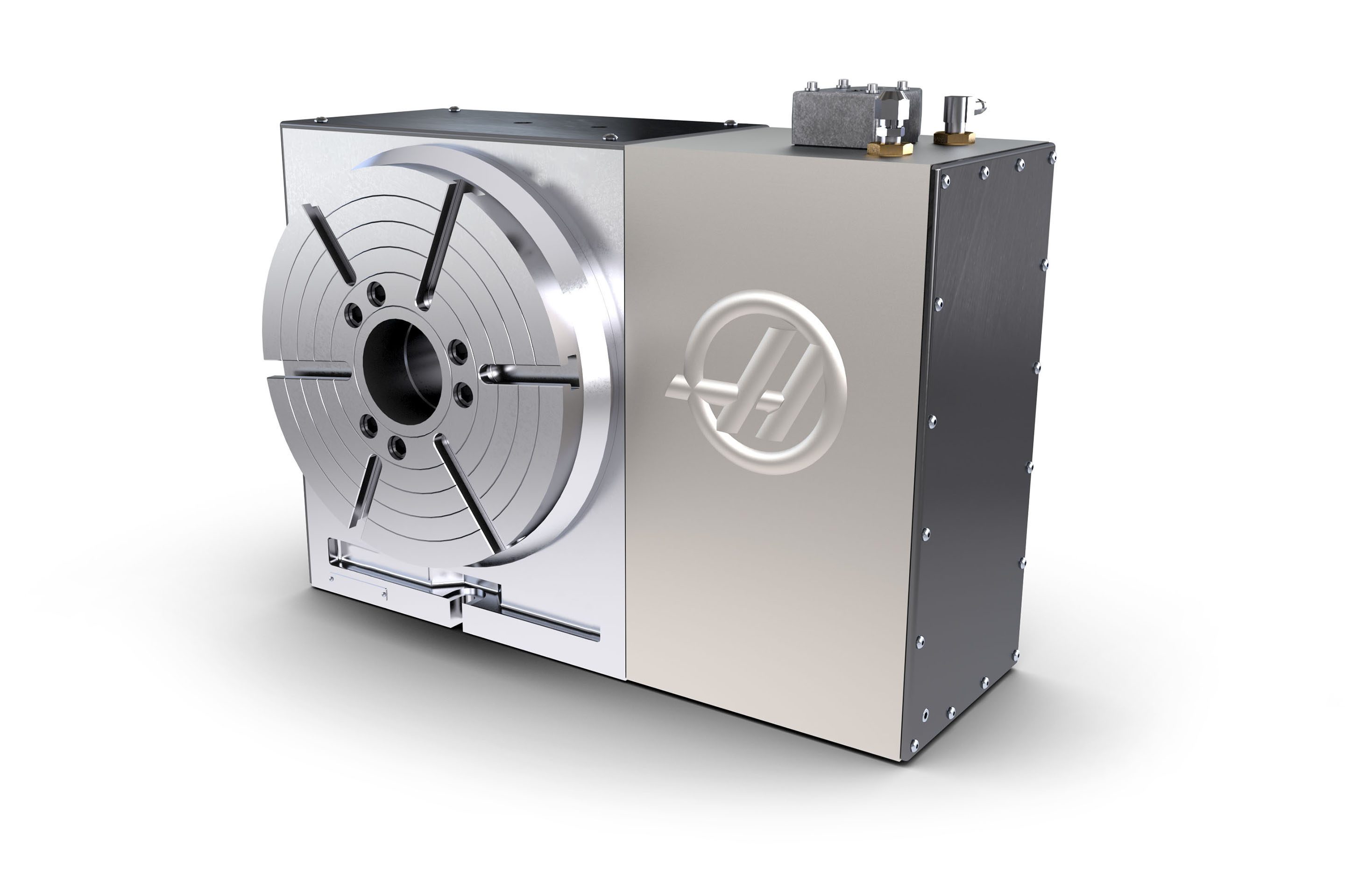
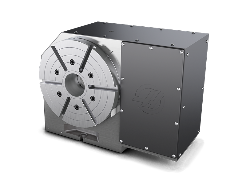
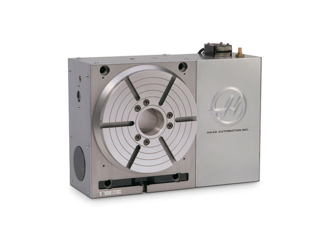
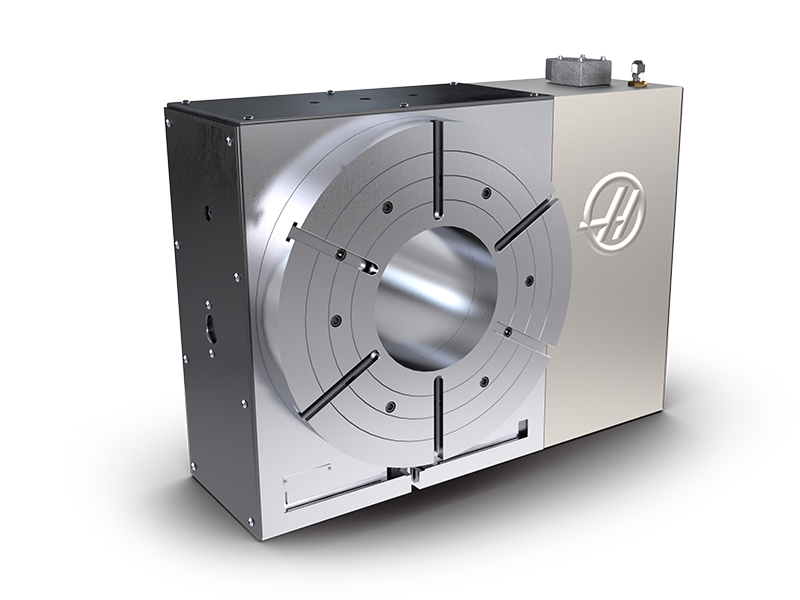
2 Back 1. INTRODUCTION 1.1 DESCRIPTION The HAAS rotary table is a fully automatic, programmable, rotary positioning device. The unit is made up of two parts: the mechanical table that holds the workpiece and the electronic unit that controls the rotation of the table. Positioning of the workpiece is accomplished by programming the angular movements into the memory of the control and then pushing the CYCLE START button on the front panel. The unit was specifically designed for rapid positioning of parts in secondary operations such as milling, drilling, and tapping. The device is especially suited to automatic machines such as NC mills and automatic production machines. The control can be remotely activated by your equipment and does not require human assistance, resulting in fully automatic operation. Furthermore, one unit can be used on several different machines, thereby eliminating the need for multiple units. TABLE The rotary table can be used in almost all of the applications where a manual rotary table can be used. Positioning of the table is accomplished through a deep-tooth engaging, self-locking worm and worm gear set. The worm is connected to a AC (DC) servo motor through a timing belt and pulley set. Odd number bolt circles and uneven hole spacing are easily handled with simple programming. The table is equipped with a pneumatic brake (HRT 450 uses air over oil). A regular shop air line of approximately 100 PSI is all that is needed to activate the brake. The HRT210SHS (Super-High Speed) Table is unique from the other rotary tables. It has no worm gear set, belt, or pulleys but uses a Harmonic Drive gear. It is directly driven by an AC servo motor and is 6 times faster than our standard HRT210. The HRT320FB uses a facegear (Hirth coupling) for extreme indexing accuracy and rigidity. It positions the platter in multiples of exactly 1. The platter lifts.070 during indexing and the table positioning is done at full rapid speed. The HRT320FB cannot be used as a full forth axis. CONTROL The rotary table servo control incorporates the latest in high-speed microprocessors and drive technology. The control was designed using extensive software to replace discrete components, thereby reducing possible failure areas. This same software also checks out the computer system upon power-up, and alerts you to component failures. Only one printed circuit board is used to control all major functions. The optional RS-232 interface can be used to upload, download, enter data, read position, start, and stop motor operation rev L June
3 1.2 LIMITATIONS The control and table are described as a semi-fourth axis. This means that the table cannot do simultaneous interpolation with other axes. Linear moves or spirals can be generated by having an axis of your mill move at the same time the rotary table moves (see the "Programming" section for details). 1.3 MACHINABLE P ART S IZE The HRT series was designed for positioning and continuous milling of medium to large size parts. When selecting a rotary table, the size of a typical workpiece and fixture must be considered and the size of the rotary table should be matched to the expected loads. As a general rule, the diameter of the part should not exceed the diameter of the rotary table platter. Also, the combined part and fixture weight should not exceed the weight of the rotary table. However, these are only guidelines. A part with a diameter larger than the platter diameter or a long overhung and unsupported part might require that the weight be less than the weight of the rotary table. Likewise, if the part is well supported (i.e. tailstock or pillow block), and the fixture and support have less than 0.003" T.I.R, then the weight might be able to be more than the rotary table weight. Common sense and good fixturing technique will generally make it possible to machine larger parts. The HRT210SHS Table was designed for lighter size parts which may require numerous tool changes and indexes, so the speed is important to reduce the cycle time. It has no brake, so this will also be a limiting factor to the size of the part. Maximum part diameter is 8.00 and maximum part weight should not exceed 40 lbs. 1.4 FEATURES RIGID DESIGN Large bearing surfaces support heavy cutting forces on large or small parts. CLASS 30 GREY IRON For added damping capacity QUICK REPLACEMENT CONDUIT For faster replacement and shorter downtime. PRE-LOADED ANGULAR CONTACT BEARINGS For better reliability and less wear. HARDENED AND PRECISION ROTARY GROUND PLATTER Ensures more accurate part machining. CNC HOBBED WORM GEAR* For high accuracy. DEEP TOOTH ENGAGEMENT For gear set; designed to provide greater accuracy and continuous milling capacity. ALUMINUM BRONZE WORM GEAR* For long life. HARDENED AND GROUND WORM GEAR* Made from 8620 chromium-nickel-molybdenum steel, hardened to Rc 60. AIR BRAKE* Built-in air brake with 100 to 1500 ft.-lb. of holding 100 PSI. (Except HRT210SHS) rev L June 2005
4 AC SERVO DRIVE* Closed loop 3.0HP (HA5CHD, HRT 160, HRT 210), 5.0 HP (HRT 310, HRT 450, HRT 600), 1.5 HP (HA5C) DC SERVO DRIVE Closed loop 0.5 HP(HRT160, HA5C), or 1.5 HP(HRT210, HRT310, HRT450, HRT600). VARIABLE FEED RATES* Variable from.001 deg./sec. to 100 deg./sec (100 deg./sec. for HRT160 and HRT320FB, 75 deg./sec. for HRT210, 60 deg./sec. for HRT310, 50 deg./sec. for HRT450, 40 deg./ sec for HRT600). RESOLUTION Standard motor resolution of.001 degrees ( ). PROGRAMMING Absolute or incremental programming. Up to 99 different steps can be stored in memory, and each step can be looped 999 more times. The ease and flexibility of programming the Haas control enables a single unit to serve you in many ways. SIMPLE EDITING Edit a program by simply writing over existing steps, or inserting or deleting a line (or several lines) between steps, with automatic program line re-numbering. SUBROUTINES Allows sequences to be repeated up to 999 times, saving programming time and memory space. AUTOMATIC CIRCLE DIVISION Program a step that automatically divides a circle into any number of equal parts (between 2 and 999). PROGRAMMABLE PARAMETERS Alter many of the basic features by performing your own basic programming. PROGRAM STORAGE Store and recall from up to seven different programs. MEMORY A non-volatile memory retains a program even when power is turned off. It also remembers the current spindle position and step number. INTERFACING Most CNC mills can be interfaced with the HRT Series quickly and easily by using a spare M function that provides a switch-closer as a signal between your mill and the RT. EMERGENCY STOP/FEED-HOLD EMERGENCY STOP can be used to feed-hold spindle movement without losing position on restart. ZERO RETURN A programmable HOME position returns the spindle to its original starting position from any point. LINEAR & SPIRAL MILLING For semi fourth-axis capability. FAST SET-UPS All connectors are quick-disconnect, ensuring fast and easy set-ups. STANDARD POWER Operates on 115VAC 15 Amps rev L June
5 OPTIONAL RS-232 INTERFACE For computer control of sending and receiving programs. 12-MONTH WARRANTY Against any defects in materials or workmanship. SYNTHETIC GEAR OIL Provides greater worm gear wear protection than conventional gear oils. *Except HRT210SHS; see below: FEATURES E XCLUSIVE TO THE HRT210SHS Harmonic Drive gear set. 3 HP A.C. Servo Motor Variable feed rates from.001 deg./sec. to 270 deg./sec. with rapids to 360 deg./sec rev L June 2005
6 1.5 SPECIFICATIONS M ODEL: H RT 160(SP) H RT 210(SP) HRT 310(SP) HRT 320FB HRT 450 HRT 600 SPINDLE Table Torque (ft./lbs) AC / DC 150/ / / / / 380 Feedrates (deg./sec.) AC / DC AC.001 to 100 DC.001 to 80 AC.001 to 100 DC.001 to 60 C to DC. 001 to 360 D 1 AC.001 to 60 DC.001 to /sec only AC.001 to 50 DC.001 to 40 AC.001 to 50 DC.001 to 40 Spindle Runout (inches) Platter Face Runout (in) Backlash (arc-sec.) N/ A Center Height (inches) / / / / / /-.001 Brake Holding PSI (ft./lbs.) INDEXING N/A 2 Indexing Accuracy (arc/sec.) +/- 15 +/ / /- 6 + / /- 3 + /- 15 +/- 15 Repeatability (arcsec.) within 10 within 10 within 10 + /- 1 within 10 within 10 Resolution (deg.) Max. Resolution (deg.) Worm Gear Dia (in") MOTOR AC Servo (Brushless) DC Servo (Brush) 3.0 HP 0.5 HP, HP / 5. HP HP HP 1.5 HP 5.0 HP 5.0 HP 1.5 HP 5.0 HP 1.5 HP Drive Ratio (Timing Belt and Pulley Set) 2:1 2:1 1: : 1 2: 1 3: 1 3.5: 1 / N/ A Worm Gear Ratio 63: 1 90:1 72: 1 72: 1 72: 1 72: 1 N/A 2 Total Gear Reduction 126: 1 OPERATING SPECIFICATIONS 180:1 1 90:1 2 50:1 144:1 144: 1 216: 1 252: 1 M ax. Air Pressure 120 PSI (40psi minimum for HRT320FB ) Power Requirements Lubrication 115V AC +/- 15 Amps Mobil SHC-630 synthetic gear oil 2 Mobil SHC-626 synthetic gear oil OPERATING ENVIRONMENT Maximum Temperature 100 Degrees F 1HRT210HS 2HRT210SHS 3HRT210S C rev L June
7 1.6 MACHINE D IMENSIONS MODEL DIMENSIONS A B C D E F G H J HRT mm (6.30") ± Ø HRT mm (8.27") ± Ø HRT210 (Brush) 210 mm (8.27") ± Ø HRT210SC 210mm (8.27 ) / Ø HRT mm (12.20") ± Ø HRT320FB (*The platter lifts.065 during positioning) HRT310 (Brush) 310 mm (12.20") ± Ø HRT mm (17.72") ± Ø HRT mm (23.62") "± Ø rev L June 2005
8 HRT SP DIMENSIONS B F A 14" E G C D WRENCH ACCESS W x 0.50 DP Front & Rear Tie Down Slots MODEL DIMENSIONS A B C D E F G HRT 160SP ± x 6.00 Depth HRT 210SP ± x Depth HRT 310SP ± x Depth rev L June
10 1.7 OPTIONAL S ERVO C ONTROL B RACKET Designed to work specifically with the Haas line of CNC mills. This bracket keeps the Servo Control in easy reach of the operator, allowing for easy programming between the Haas mill and Rotary table. Contact your Haas dealer to order. (Haas part number: SCPB) Installed Servo Control Bracket 1.8 HAAS T AILSTOCKS Tailstocks must be properly aligned to the rotary table before using. Clean bottom surface of tailstock casting before mounting to mill table. If there are any noticeable burrs or nicks on the mounting surface, clean them with a deburring stone. See the Haas tailstock manual ( ) for pneumatic tailstock s operating pressure. Tailstocks cannot be used with the HRT320FB table rev L June
11 2. SETTING UP THE HAAS ROTARY TABLE 2.1 GENERAL S ETUP 1. Fill out the warranty card and mail it in. (Very Important). 2. Place the indexer on your machine. Route the cable from the table such that it avoids tool changers and table edges. Slack must be provided for your machine"s movements. If the cable is cut, the motor will fail prematurely. Secure the HRT Rotary Table to your machine s T-Slot table as shown below. NOTE: The HRT 160, 210, 450, and 600 Rotary Tables can be secured as shown: Remove Top Cover to Access Toe-Clamp Pockets 1/2-13UNC T-Nuts, Studs, Flange nuts and Washers* Bottom View of Casting Clamping Tool Assembly (2) 1/2-13UNC T-Nuts, Studs, Flange Nuts, and Washers * Toe Clamp Assembly* 1/2-13UNC T-Nuts, Studs, Flange nuts, and Washers 1/4-20UNC SHCS (4) Toe-Clamp Assembly (2)* *NOTE: Toe-Clamp Fasteners are not supplied. *Standard stud mounting, front and rear For extra rigidity, use additional Toe-Clamps. NOTE: The HRT 310 can be secured as shown: 3/4-10UNC X 8 SHCS (4) Thru C Bore X 0.80 DP Req. 1/2-13UNC T-Nuts, Studs, Flange nuts and Washers Fixture Plate 3. Connect the indexer to run as a full-fourth or semi-fourth axis. See the following figure. For fullfourth axis, the indexer is connected directly to the HAAS mill control at the connector labeled A- Axis, and is the desired connection rev L June 2005
12 ON POWER SERVO ON CYCLE START EMERGENCY STOP DEGREES 0 JOG OVER HIGH LOAD LOAD 9 ZERO RETURN CLEAR ZERO SET MODE RUN PROG SCAN DISPLAY STEP SCAN SEMI-FOURTH AXIS OPERATION TO MILL RS232 PORT OR INTERFACE CABLE PORT 4TH AXIS FULL-FOURTH AXIS OPERATION STEP DEGREES Servo Control RUNNING OVER - + JOG ZERO 8 9 RUN 0 - SERVO CONTROLLER TO MILL 4TH AXIS PORT 4TH AXIS Note: Your HAAS mill must have the 4th axis option to run full-fourth and must be configured as brush or brushless to be compatible with your indexer. Brush configuration uses one cable and one connection at the A-axis port on the control. Brushless uses two cables and two connectors at the A-axis port. (HRT320FB cannot be run directly from a mill) 4. Route the cable over the back of the mill sheetmetal and install the cable clamp. The bottom plate of the clamp assembly must be removed and discarded before installing the clamp to the mill. Assemble the clamp to the mill as shown Shipping Plate rev L June
13 5. If adding an indexer to a Haas mill the settings must be set for the specific table. Refer to the instructions in the mill manual or call the Haas service department. 6. Semi-Fourth Axis: Secure the servo control in servo pendant bracket (Haas part number SCPB) as seen at the end of the introduction section. 7. Connect the large black cable from the table to the controller. CAUTION: Never connect or disconnect this cable with the power on! Instant failure will result! 8. Semi-Fourth Axis: Connect the AC line cord to a 120V AC grounded receptacle. The cord is a three-wire ground type, and the ground must be connected. Power is 120VAC. The power service must supply a minimum of 15 amps continuously. Conduit wire must be 12 gauge or larger and fused for at least 20 amps. If an extension cord is to be used, use a three-wire ground type and the ground line must be connected. Avoid outlets that have large electric motors connected to them. Use only heavy duty 12 gauge extension cords capable of 20 amp load. Do not exceed a length of 30 feet. 9. Semi-Fourth Axis: Connect the remote interface lines. See Interfacing to Other equipment section. 10. Connect the table to a standard shop air line (120 PSI Max). The line pressure to the brake is not regulated. Do not exceed the maximum pressure. NOTE: HAAS recommends the use of an in-line air filter/regulator for all tables. The air filter will keep contaminates from entering the air solenoid valve. 11. Check the oil level. If it is low, add oil. Use MOBIL SHC-630 synthetic gear oil (Viscosity Grade ISO 220). For the HRT210SHS use Mobil SHC-626 synthetic gear oil (Viscosity Grade ISO 68). 12. Save the packing materials in case you need to ship the unit. 13. At the end of the workday or shift, it is important to clean the rotary table. The table should be free of any chips or grime. Clean with a chip brush and apply a coat of a rust preventative. CAUTION! Do not use air gun around front or rear seals. Chips may damage seal if blown in with an airgun. 14. Turn on the mill (and servo control, if applicable) and home the table by pressing the Zero Return button. All Haas indexers home in the clockwise direction as viewed from the platter. If the table homes counter-clockwise, press E-stop and call the Haas service department rev L June 2005
16 RS-232 Responses The xp command is presently the only command that responds with data. It will return a single line consisting of: xnnn.nnn xnnn.nnnr xon (servo at standstill at position nnn.nnn) OR (servo in motion past position nnn.nnn) OR (servo is off with reason n) OR xln (servo HOME position lost with reason n) 2.4 THE R EMOTE I NPUT The CNC Interface Cable provides a basic method of communication between a non-haas mill and Haas Servo Control/Rotary Head. Since most CNC machine tools are equipped with spare M-codes, Semi-fourth axis machining can be achieved by connecting one end of the CNC Interface Cable to any one of these spare relays (switches), and the other to a Haas Servo Control unit. Indexing commands for the rotary unit are stored only in the Servo Control s memory, and each pulse of the host machine s relay triggers the control to index to its next programmed position. After finishing the index, the Servo Control signals that it has finished and is ready for the next pulse. A remote socket is provided on the back panel of the control unit. The remote input consists of a cycle start line and a cycle finish line. To connect to the remote, you will need a connector supplied by HAAS (or one obtained from a local source) that can be used to trigger the controller from any one of several sources. The cable connector used is a male four-pin DIN connector. The Haas Automation part number is (Amphenol part number is T ). The The Haas Automation part number is for the panel receptacle in the control box is (Amphenol part number T ). Cycle Start Figure 2 shows the connector as viewed from the rear panel of the control unit. When pins 3 and 4 are connected to each other for a minimum of 0.1 seconds, the control will index the head one cycle or step. To index again, pins 3 and 4 must be opened for a minimum of 0.1 seconds. Under no circumstances should power be applied to pins 3 and 4. A relay closure is the safest way to interface the control to your equipment. When a cycle start is implemented, pin 3 supplies a positive 12 volts at 20 milliamps and pin 4 is connected to the diode of an opto-isolator that grounds to chassis. Connecting pin 3 to pin 4 causes a current to flow through the diode of the opto-isolator, triggering the control. If the control is used around high frequency equipment such as electric welders or induction heaters, you will need to use shielded wire to prevent false triggering by radiated EMI (electromagnetic interference). The shield should be attached to earth ground rev L June
17 Cycle Finish Figure 2. A Typical CNC Interface. If your application is in an automatic machine, such as a CNC mill, the feedback lines (pins 1 and 2) should be utilized. Pins 1 and 2 are connected to the contacts of a relay inside the control and have no polarity or power on them. They are used to synchronize the automatic equipment with the controller The feedback lines provide a switch closure through a relay inside the Haas control box to let your machine know when the table has finished indexing. The relay can be used to Feed Hold NC machine movements or it can be used to cancel the M function. If your machine is not equipped with such an option, another alternative may be to dwell for a period of time longer than it takes the control to index the head. The relay will trigger for all cycle start closures except a no-operation code of rev L June 2005
18 2.5 REMOTE O PERATION WITH M ANUAL E QUIPMENT The remote connection is used when you wish to index the unit other than by the START switch on the front panel. This frees the operator from having to touch the control to start indexing. For example, using our optional remote quill switch (Haas P/N RQS) for Bridgeport milling machines, every time the quill handle is retracted it touches a micro switch on the clamp and the indexing head will rotate automatically. This eliminates the need to remove your hand from the quill, increasing production dramatically. Using a magnetic base, an aluminum bracket, and a micro-switch you can get the unit to index almost anywhere you wish. Use the switch to index the unit when you are milling. Every time the table comes back to a certain position, a simple bolt on the table can close the switch, indexing the unit. Refer to Figure 2. By simply connecting pins 3 and 4 together, the control will index. Be careful that you do not apply power to these lines (3 and 4 only). You do not need to hook up the feedback pins 1 and 2 unless you want the control to start another mechanism such as an automatic drilling head. The feedback pins (1 and 2) do not need to be connected for the control to operate. Color-coded remote interface cables are available, as an option, to help the users understand the M-function hookup. They are coded as follows: 1 = red 3 = black 2 = green 4 = white 2.6 REMOTE O PERATION WITH CNC EQUIPMENT NOTE: All Haas controls come standard with 1 CNC interface cable. Additional CNC interface cables can be ordered (Haas P/N CNC). CNC machines have Miscellaneous functions called M functions. These control external switches (relays) that turn things on or off (i.e., spindle, coolant, etc.). Most CNC controls provide some degree of access to the M functions, with most late model machines providing several spare relays just for this purpose. The HAAS remote cycle start line is hooked into the normally open contacts of a spare M function relay. Our remote feedback lines are then connected to the M function finished line (MFIN), which is an input to the CNC control, to cancel the M function and proceed to the next block of information. On late model CNC machines, interfacing the unit is relatively simple, if you know where to make the connections. Your machinery dealer is the best source for this information rev L June
19 ON ON 0 JOG OVER HIGH LOAD LOAD 9 SET RUN STEP SCAN 2.7 REMOTE O PERATION WITH A FANUC CNC CONTROL FANUC control set-up requirements There are several requirements that must be met before a Haas Servo Control can be interfaced with FANUC controlled mill. These are as follows: 1. FANUC control with custom macro enabled and parameter 6001, bits 1 and 4 set to A serial port on the FANUC control must be available for exclusive use by the Haas Servo Control while DPRNT program is running. 3. Single axis Haas Servo Control and Indexer/Rotary table. Note: A dual axis control will not work in this application as the RS-232 communications port is being used for internal communication. 4. RS-232 shielded cable 25 DB25M / DB25M (null modem not required) Radio Shack Catalogue no.rsu (see pinout below) 5. Shielded M-code relay cable Haas Automation Part Number : CNC DB25 pinout: * * 20-20* *Not connected in the brushless control CNC MILL W/FANUC CONTROL HAAS ROTARY CONTROL HAAS ROTARY CONTROL RS-232 Cable POWER STEP DEGREES SERVO CYCLE START RUNNING OVER EMERGENCY STOP - + JOG ZERO ZERO RETURN CLEAR ZERO 8 9 RUN MODE PROG DISPLAY SCAN Control Cable 0 - M Function Relay +24 Volts M FIN Signal CNC MILL CNC INTERFACE CABLE 4 Pin Din Connector Rear of Controller OHM HAAS INTERNAL CYCLE START +12 Volts CYCLE FINISH Figure 3. A Typical CNC Interface rev L June 2005
20 Haas parameters Once the above requirements have been met you can revise the parameters of the Haas control. Listed below are the parameters that will need to be changed. Parameter 1= 1 Parameter 2 = 0 Parameter 5 = 0 Parameter 8 = 0 Parameter 10 = 0 Parameter 12 = 3* Parameter 13 = Parameter 14 =65535 Parameter 21 = 6* (see table 1) Parameter 26 = 3* (see table 2) Parameter 31 = 0* Parameter 33 = 1 Table 1 Table 2 0= RS 232 upload / download programs 1= U 0 = = = = V 3= W 2 = = = X 5=Y 4 = = =Z 7,8 AND 6 = = RESERVED Fanuc Parameters The Fanuc control parameters must be set as follows to successfully communicate with Haas Control. Baud Rate 1200* Parity Even (Required setting, do not experiment) Data Bits 7 or ISO (If CNC control defines Data bits as word length + parity bit then set to 8) Stop bits 2 (Required setting, do not experiment) Flow control XON / XOFF Character Coding (EIA/ISO) ISO (Required setting, EIA will not work) DPRNT EOB LF CR CR (CR is required, lf is always ignored by Servo control) DPRNT Leading zeroes as blanks off *Initial settings. Experiment with these settings only AFTER interface is functional. NOTES: 1. Be certain to set FANUC parameters related to actual serial port connected to Haas Servo Control. The parameters have been set for remote operation. You can now program, or run an existing program. There are several key items you need to consider to insure your program will run successfully. First and foremost DPRNT must proceed every command sent to the Haas Control. The commands are sent to the controller in ASCII code and terminated by a carriage return (cr.). All commands must be proceeded by an axis select code (U, V, W, X, Y, Z), parameter 21 = 6. For this explanation Z will represent the axis code rev L June
23 2.9 HAAS A6AC AIR C OLLET C LOSER The A6AC collet closer easily bolts to the back of the HRT A6 (see Figure 1a). The drawbar and collet adapters are designed to mate with the Haas A6/5C spindle nose. The optional A6/3J and A6/16C may be obtained from your local tooling distributor. NOTE: A special drawtube adaptor is required for the 16C and 3J. Make sure to supply tooling distributor with spindle/drawbar details as shown in figure 1-b. Figure 1-a. A6AC collet closer shown mounted to an HRT A6. D E A - MAX. B-MIN. F G A - MAX. (Tube Extended) B - MIN. (Tube Retracted) C - Spindle Type and Size D - Draw Tube Thread Data 1 - Diameter of Thread 2 - Pitch 3 - Internal Thread 4 - Length of Thread E - Draw Tube I.D. F - Draw Tube O.D. G - Spindle 100 psi line pressure.640*.760 A1-6 17/8-16UN-2B / C Figure 1-b. Drawtube to spindle dimensions (extended/retracted) rev L June 2005
24 Clamping Force and Air Supply The A6AC is a 1-3/4 diameter thru-hole type closer which is adjustable from the rear. It holds parts by utilizing spring force to provide up to of longitudinal movement and up to 5000 lbs. of draw force at 120 PSI shop air pressure. Adjustment To adjust the collet closer, align a collet with the keyway, push the collet into the spindle, and turn the drawbar clockwise to pull the collet in. To make the final adjustment, place a part in the collet, turn the air valve to the UNCLAMPED position to charge the cylinder and compress the spring mechanism, then tighten the drawbar until it stops. Back off 1/4-1/2 turn and turn the air valve to the CLAMPED position. This will be adjusted for maximum clamping force. To reduce the clamping force, back off further on the drawbar or regulate the air pressure down before adjusting. Collet Sticking NOTE: To prevent excessive wear and collet sticking, make sure collets are in good condition and free from burrs. A light coat of Molybdenum grease on the collet wear surfaces will extend the life of the spindle / collet and help prevent sticking. When the air supply is turned on, the drawbar is kicked forward and releases the collet. Increasing the air pressure can help stop the collet sticking; however, do not exceed 200psi into the cylinder. Backing off further on the drawbar during final adjustment may also reduce collet sticking. WARNING! Do not index the Rotary Table while the A6AC air valve is in the ON position. This will put excessive friction on the worm gear system and cause premature wear rev L June
26 A) Main POWER switch to turn the unit on (back panel). B) CYCLE START begins a step, stops a continued operation, inserts a step, or turns the servo on. C) EMERGENCY STOP turns off the servo when on and aborts the step in progress. D) JOG causes the servo to move in either the forward or backward direction at a rate defined by the last numeric key pressed. E) Load meter LED. If LEDs are illuminated continuously during a low feed rate or when stationary, the following conditions apply: HIGH LOAD: Indicates overload level, excessive load or workpiece support misalignment. Hi-LoAd or Hi Curr alarms may occur if not corrected. (See "Troubleshooting" section) OVERLOAD: Indicates 2x overload level, excessive load or workpiece misalignment. Hi LoAd or Hi Curr alarms will occur if not corrected. Damage to motor or table may result. (See "Troubleshooting" section) NOTE: It is normal for the LEDs to be illuminated during a rapid movement or high duty cycle. F) ZERO RETURN causes the servo to return to HOME position, search for mechanical HOME, delete a step, or move forward to the mechanical offset. G) ZERO SET clears the entered data, resets program to 0, or defines the present servo position as HOME. H) MINUS KEY selects negative step values or Prog/Upload/Download functions. I) STEP SCAN scans step numbers from 1 through 99. J) DISPLAY SCAN scans the display to show either Position, Step Angle, Feed Rate, Loop Counts, or G Code. K) MODE / RUN PROG switches from RUN mode to PROGRAM mode (blinking display). L) Data entry keys and jog speed selection. M) Displays show current data, i.e., a current spindle position of 180. N) Indicates what data is being displayed. Either P, F, L, blank, or G for Position, Feed Rates, Loop Count, Step Angle, or G Code. O) Present step number. Step numbers 1 to 99 are available. Also displays errors at turn on rev L June
27 3.2 TURNING T HE S ERVO O N There is a single 115V 15 amp supply required by the controller. Ensure that the front panel power switch is turned off (Brushless units have the power switch on the rear) and connect the motor cable from the table and the power cord. Turn the controller on. The display will show: HAAS nn where nn is the software revision number. That number should be used when describing problems to HAAS. If any other message is displayed, refer to the "Error Codes" section of this manual. The number only remains in the display for about one second. The front panel displays should indicate: Por On This indicates that the servo is turned off (no power is applied to the closed-loop motor). In addition, the internal battery is checked at power-on and if the battery is low the following message is displayed: Lo bat Pressing any key will allow you to continue operation, but the low battery may have caused loss of your program parameters. Press the front panel START switch once. The panel should now indicate: 01 no Ho This indicates that the motor is powered, but the zero position is not yet defined. 3.3 AUTOMATICALLY F INDING T HE Z ERO P OSITION Press the ZERO RETURN button to start the automatic homing operation. When the table stops, the display will indicate: 01 Pnnn.nnn 3.4 MANUALLY F INDING T HE Z ERO P OSITION Use the left/right JOG switch to position the table to the position that you want to use as zero and then press and hold the CLR key for three seconds. The display should now indicate: 01 P This indicates that the zero position is established and the controller is ready to begin normal operations. If a different position is to be used as zero, jog the table to the new position and press the CLR key for three seconds. The display will again indicate: 01 P If you had previously cleared a new HOME position for the table, the display will show a non-zero position. In this case, press the ZERO RETURN button once more and the table will move forward to the pre-defined zero position rev L June 2005
28 3.5 JOGGING Jogging of the motor can be done with the front panel JOG switch. The jog speed is selected with the front panel number keys and is a fraction of the maximum feed rate set by the parameters. The jog speeds (for the HRT 160) are: Number pressed Speed (% of maximum) Jog speed (for 80 deg/sec max.) Deg/sec Deg/sec Deg/sec Deg/sec Deg/sec (default) Deg/sec Deg/sec Deg/sec Deg/sec Deg/sec If the control is set up for linear motion, positive and negative travel limits are possible. If a step is started which would have caused the control to exceed travel limits, the following message is shown: 2 FAr and the control will not execute the step. (See parameter 13 and 14, travel range) 3.6 ERROR C ODES When the controller is first turned on, a set of self tests is run and the results may indicate a controller fault. Any of these could result in an En display of one of the following codes: Blank front panel E0 EProm FP Short re Short E3 ram E4 batt E5 Pio2 E6 Pio3 Lo Volt E8 Encod E9 inter EA no go Eb nmi Ec Pwm Ed cloc EE Au in Lo bat rls Err Program CRC failure (bad RAM, or cycle power if bad ROM to RAM program transfer.) EPROM CRC error Front panel switch closed (or PIO fault) Remote START switch closed and enabled RAM cannot store data Saved program is in error (low battery) PIO2 is bad PIO3 is bad Power-fail interrupt (low line voltage) Encoder chip bad Interrupt problem Keep alive circuit failure NMI sense bad PWM generation bad 1 khz signal missing Auxiliary input 2 shorted Low battery (Get serviced) Exceeding maximum allowed rotary scales compensation. HRT210SC only Intermittent low voltage errors or power failures may be the result of inadequate power to the controller. Use heavy duty extension cords only and keep them as short as possible. Make sure power service is a minimum of 15 amps at the plug and that the voltage is a minimum of 115 V AC rev L June
29 0 too SL (Zero margin too small) Zero margin too small is the distance between the home switch and the final stopped motor position, after seeking home, is either less than 1/8 or greater than 7/8 of a motor revolution. This alarm may occur while homing the rotary table. The distance between the home switch and the final motor position at zero is less than 1/8 of a motor revolution. To prevent this alarm, parameter 45 must be set properly. Start with the default value for parameter 45 (0) and add 1/2 of a motor revolution (1/2 motor revolution is equal to the value in parameter 28 divided by 2). Home the rotary table after the new value for parameter 45 has been entered. There are no user-serviceable parts inside, so refer all problems to HAAS Automation for repair. 3.7 SERVO O FF C ODES At any time the servo is turned off, a reason code is displayed along with the following codes: Por On Ser Err E-StoP Hi LoAd rs-232 Air-Hot EncodEr REncodEr Hi Curr EncodES rencodes Hi VoLt CABLE rcable PHAS Er dr FLt trans Indr dn Power was just turned on (or failed prev.) Servo following error too large Emergency stop Software fuse Remote RS-232 commanded off Motor overheat sensor Z channel fault (bad encoder or cable) Rotary scale Z channel fault (bad rotary scale encoder or cable) HRT210SC only Over current limit (stalled or PCB fault) Z channel missing (bad encoder or cable) Rotary scale Z channel missing (bad rotary scale encoder or cable) HRT210SC only Regen overheat (high line voltage) Break detected in encoder cable wiring Break detected in rotary scale cable wiring (HRT210SC only) Power up phase error (Brushless units only) An overcurrent or drive fault.( Brushless units only) Encoder transition fault had been detected by the brushless circuitry. Platter not fully up (HRT320FB only). Can be caused by low air pressure. 3.8 EMERGENCY S TOP Pushing the EMERGENCY STOP button will turn the servo off and cause the spindle to decelerate and stop. Position will not be lost. If the step was not completed you will still be on that step. Push CYCLE START to turn the servo on. The remote cycle start and cycle finish will not function until the EMERGENCY STOP is removed by pushing the START button. If an EMERGENCY STOP is performed, the display will indicate an: E-StoP CE machines have an Emergency-stop switch on the top of the control. Pressing the E-stop switch will turn off the servo and aborts the step in progress rev L June 2005


 8613371530291