
hydrostatic rotary table free sample
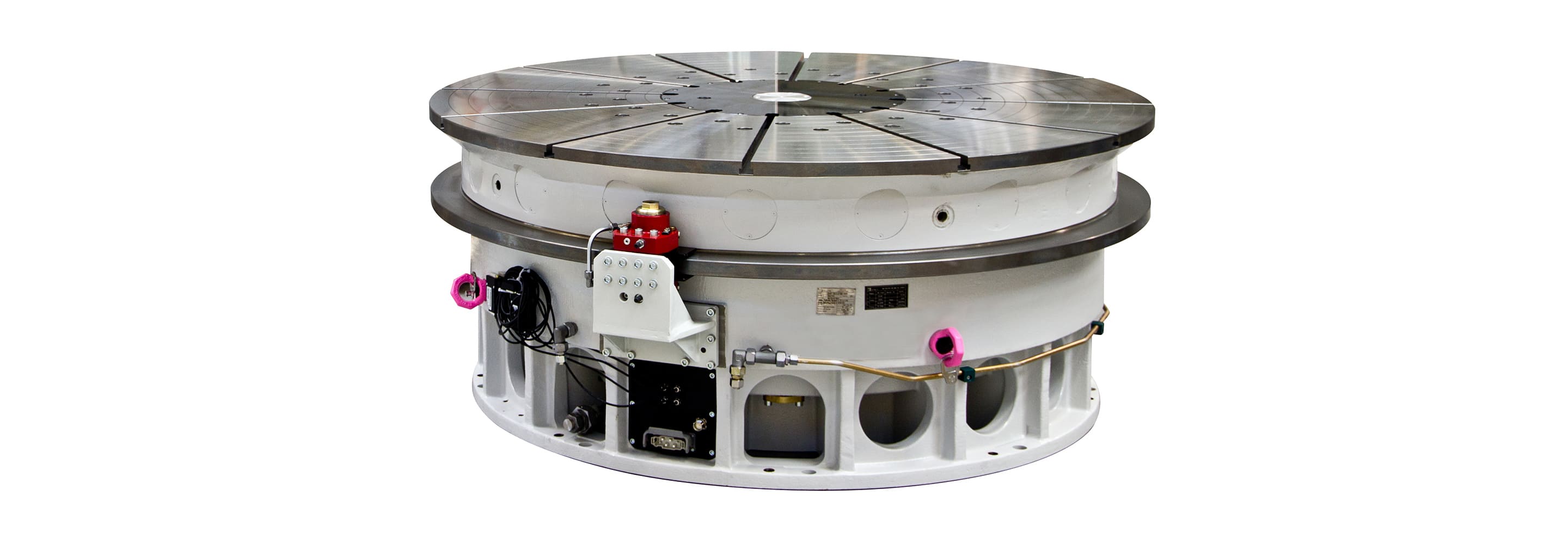
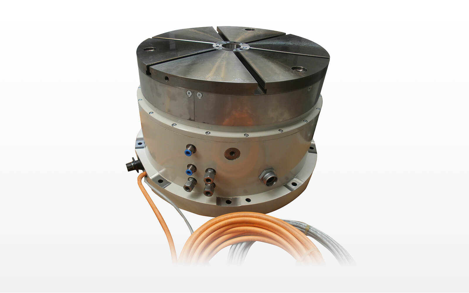
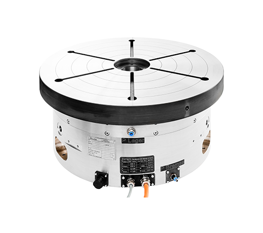
The hydrostatic rotary tables from ZOLLERN impress with their durability and a high concentricity and axial runout accuracy. Thanks to the ZOLLERN bearing clearance compensator, the optimal pocket pressure is set automatically and independently of production tolerances. The freedom from friction at low speeds prevents slip stick and therefore allows maximum positioning accuracy.
This is an example of a hydrostatic spindle designed for high speed grinding with CBN grinding wheels. The small bearing diameter in combination with high surface speed allows the use of CBN wheels even for undercuts in a camshaft application.
Rotary transmission leadthroughs serve as a rear inter face for fluid transmission into the spindle. A hydromechanic clamping unit or integrated clamping cylinder can be actuated with the media oil, air and coolant. The transmission of oil and coolant is possible at rotational speed.
[51] Int. Cl B23d 7/08 [58] Field of Search 90/58 H, 58 R, 56; 408/71, 90; 308/9, 5 R; 74/813 R; 51/240 T [56] References Cited FOREIGN PATENTS OR APPLICATIONS 1,047,342 11/1966 Great Britain 90/58 Primary Examiner-Gil Weidenfeld Att0rneyWolfe, Hubbard, Leydig, Voit & Osann Nov. 20, 1973 [57] ABSTRACT An improved work carrying table for machine tools including pivotal and outer hydrostatic bearings for slidably supporting the table platen on its base and for providing precise indexing and rotation of the platen. The outer hydrostatic bearings each comprise a gib structure with a bearing surface situated between a way mounted on the platen and preload actuators recessed in one of the oppositely extending arms of a fixed preload member mounted on the base. Each preload actuator comprises a flexible bladder containing 5 Claims, 9 Drawing Figures PATENTED NOV 20 I975 sum 10F 5 PAIENIEUnuvzo 1915 3772.961 sum 2 OF 6 PATENTEU NOV 2 0 I975 SHEET. 5 BF 6 PATENTEU "BY 20 I973 SHEET 8 OF 6 I-IYDROSTATIC ROTARY TABLE DESCRIPTION OF THE INVENTION This invention relates generally to work carrying tables for machine tools and, more specifically, to improved work carrying tables having preloaded hydrostatic bearings. resutting Work carrying tables with preloaded hydrostatic bearings have been advantageously used for many years. Hydrostatic bearings reduce wear and thus preserve the precision of the bearings without the need for manually adjustable gibs. By the application of a biasing force to the hydrostatic bearings, distortion of the bearing structures and the table platen under heavy loads is significantly reduced and the indexing accuracy of the table is increased by the resulting stiffness of the bearing.
However, in certain prior work carrying tables, particularly those which carry heavy workpieces, the large preload biasing forces applied to the hydrostatic bearings often create force couples within the bearing structure which can cause their own distortion of the platen surface. It has also been difficult in certain prior tables to maintain the preload forces uniform along the length of the bearing structures with the result that the benefits of preloaded hydrostatic bearings are reduced and there is resultant distortion of the platne surface by heavy workpieces. I
One object of the present invention is to provide a work carrying table having preloaded hydrostatic bearings for accurate indexing of the table and in which the preloading forces do not distort the surface of the table platen. A related object is to provide such a table which is also adapted for precision contour machining of workpieces supported on the rotating table platen.
A further important object of the invention is to provide a work carrying table having preloaded. hydrostatic bearings in which the preload forces are uniform along the bearing structure. A related object of the invention is to provide a"preloaded hydrostatic bearing structure for work carrying tables having a plurality of hydraulically operated bladder assemblies, each of which applies a uniform preload force to an underlying gib section of the bearing structure.
FIG. 3 is an enlarged, broken vertical sectional view illustrating a supporting and a preload hydrostatic bearing incorporated in the rotary table of FIG. 1;
Referring more particularly to FIG. 1, the invention is there exemplified in a rotary work table 20 which may be used to support and rotate a workpiece relative to the tool spindle of a machine tool such as a horizontal boring, drilling and milling machine (not shown). The rotary table comprises a work table or platen "21 pivotally supported upon a base member 22 which, in turn, may be mounted on or adjacent the machine tool in any suitable manner. For indexing the platen 21 to a chosen position or rotating it to perform a contour machinigng I operation on a workpiece mounted thereon, the work table is provided with a preloaded table drive 25 mounted within a gear box 26 projecting radially of the base 22. For detecting the position of the platen 21, there is included a rotary transducer 32 mounted in a recess 33 in the base of the table. The transducer 32 may be of a well known type such, for example, as one known in the trade as anflnductosyn unit. A hub assembly 37, including hydrostatic bearing 38, centers the platen on the base for sliding rotation of supporting outer hydrostatic bearings 41, 42. The outer bearings 41, 42 are proloaded by a preload hydrostatic bearing assemby 40 comprising preload hydrostaticbearings 43, 44 which coact respectively with the bearings 41, 42. I
The base 22 is formed by two annular supporting bearing surfaces 65, 66 in direct facial alignment with the supporting bearing surfaces 56, 61 respectively of the annular ways 50, 51 to form the supporting hydrostatic bearings 41, 42 wherein each supported bearing surface is slidably engaged by its respective supporting bearing surface through a film of pressurized oil (FIGS. 1 and 4). To complete the hudrostatic bearings 41, 42, pressurized oil at approximately 300 psi. is supplied from 1,000 psi. source via capillary restrictors (not detailed) mounted on manifold 73 and via conduits 74 to a series of spaced ports 75 along each supporting bearing surface 65, 66 of the base and distributed by means of pads or grooves 76 extending from each port 75 (FIGS. 7 and 9). Between the grooves spaced circularly about the annular supporting bearing surfaces 65, 66 is an epoxy resin dam 78 which is flush with the bearing surface. The ports 75 and grooves 76 are of small diameter relative to the width of their associated bearing surfaces 65, 66; because of this and the restrictors, the flow of oil to the supporting bearing surfaces is regulated to insure the desired hydrostatic bearing function. The maximum pressure at the ports and grooves decreases more or less linearly from the ports and grooves to the edges of the bearing surfaces where relief passages, such as the series of radial drain channels 79, 80 (FIG. 1) are provided to carry off exhaust oil to a sump in the base 22 (not shown).
Provision is made in the preload hydrostatic bearing assembly 40 for preloading the hydrostatic bearings to achieve accurate indexing and rotation of the platen 21 without distortion of the platen surface 47 (FIGS. 1, 3 and 4). This is accomplished by means of a preload member 88, which in the present instance is an annular ring or way of generally T-shaped cross section, secured to the table base concentrically with respect to the hub assembly 37, a pair of preload actuating means 89, recessed respectively within one of the laterally extending arms 94, of the preload member of annular way 88, and a piar of preload gibs 98, 99 situated respectively between the preload bearing surface 57 of the L-shaped inner way 50 and the actuating means 89 and between the preload bearing surface 61 of the Z- shaped outer way 51 and the actuating means 90.
Taking, as an example, the elements associated with the inner way 50, it will be noted that the preload gib 98 is fashioned of a plurality of arcuate gib sections 100 (FIG. 2) situated end to end to form an annular ring. Each gib section 100 is a flat bar laterally confined between a shoulder of the arm 94 and a leg 106 of the annular ring 88. The clearance dimensions are such that the gib 98 is permitted to float vertically and laterally a slight amount. The lower face 108 of each gib section has been machine ground flat to act as a hydrostatic bearing surface and has appropriate ports 110 and grooves or pads 111 for distributing pressuirized oil at approximately 380 psi. as previously described. Each gib section has a number of inter-connected vertical and lateral bores 118,119 connecting each port 110 to a nipple 123 that extends through a bore 124 in the leg 106 into the annular cavity 125. Each nipple is connected to one of the conduits 129 which in turn is connected to a corresponding one of the conduits 130 by one of the cylindrical manifolds 133, 134 with the conduit 130 leading via a corresponding capillary restrictor (not detailed) in the capillary manifold 135 to the pressurized oil source.
A plurality of arcuate gib sections 100 (FIG. 2) are also operatively interconnected to form the preload gib 99 and connected to a pressurized oil source of approximately 1,000 psi. thru a capillary restrictor in the same manner as the gib sections of preload gib 98 to operate with the preload bearing surface 61 of the outer way 51 as the preload hydrostatic bearing 44.
The preload actuating means 89 (FIGS. 2, 4 and 5) which is operatively associated with the inner way 50 and the preload gib 98 to preload the hydrostatic bearing 41 is formed of a plurality of identical actuators 138 separated end to end by a plurality of cross-blocks 140 to form an annular ring. The repload actuating means 90 associated with outer way 51 and preload gib 99 is comprised of similar actuators and cross-blocks (FIGS. 2, 4 and 5). but in this case the actuators are formed with areas of slightly greater radius than those associated with the inner way 50.
The preload actuating means 89, 90 are respectively mounted within recesses 156, 157 in arms 94, 95 with substantially equal spacing between the core plates 147 and the boundaries of the recesses and are in contact with the top surfaces of the preload gibs 98, 99 with the ends of each gib section 100 preferably underlying a cross-block 140 (FIGS. 2-4). The pressurized oil is provided to the preloading actuating means from a pressure source through a port in the base (not shown). Connecting this port to each of the actuator bladders 141 is a conduit 160 that is connected through the cylindrical manifold 133 to a supply conduit 16]. The supply conduit extends through the cavity 125 and has branch conduits 162 that interconnect it through bores 165 in the annular ring 88 with the conduits 151 of the individual actuators 138 (FIGS. 2-4 and 7). Because of the relative orientations of the gibs 98, 99 12 and their respective actuating means 89, 90 and the uniform pressure provided to all the actuators 138 of the actuating means from a single pressure source, the actuating means will exert a constant, uniform preload force between the core plates and the gibs. The latter are free to float slightly, so that the preload forces on the preload hydrostatic bearings 43, 44 are uniform and the clearances in the bearings are substantially uniform even when the table is deflected under large unbalanced loads. preload the ring Another important advantage of this construction is that the preload forces exerted on the hydrostatic bearings 41, 43 and 42, 44 are not applied to the platen to distort its upper surface 47 (FIG. 4). The inner preload actuating means 89 exerts a compression force on the inner arm 94 and screws 167 or other means mounting the T-ring to the base exert a tension force on the leg 106. The combination of these forces results in a clockwise force couple being applied to the body 169 of the preload way or T-ring 88. On the other hand, the outer preload actuating means 90 exerts a compression force on the arm 95 and screws 168 or other means mounting the T-ring 88 to the base exert a tension force on the leg 107. The combination of these forces results in a counterclockwise force couple being applied to the body 169 of the T-ring 88. These two force couples, because they are in opposite directions, tend to cancel out. Furthermore, whatever slight distortion there is in the T-ring 88 is not transmitted to the platen because of the clearance provided between the ring and the platen that allows the ring to distort a slight amount without contacting the platen.
As noted earlier herein, the platen 21 is centered on the base 22 and held against radial motion by the hub assembly 37 (FIGS. 1 and 2). There is formed in the center of the platen a step bore 175 within which is fixedly secured a pivot post, 177. An upstanding cylin-- drical hub 180 is fixedly attached to the base by a suitable means. The hub 180 has an inner bore 184, to receive a mating cylindrical portion 185 of the pivot post 177 and is formed with a series of hydrostatic pads 189 to provide hydrostatic bearing 38 between the cylindrical hub and pivot post which is machined to provide a hydrostatic bearing surface to allow frictionless rotation between the pivot post and the inner bore. Pressurized oil at approximately 500 psi. is supplied to each pad 189 by a conduit via a capillary restrictor (not detailed) in the capillary manifold 135 and is distributed through the hydrostatic bearing 38 as previously described. A sealing and pilot ring 194 is secured within a counterbore 199 of the base and held in place by an overlapping bottom edge 200 of the hub 180. Mounted in the bottom of the base and connected to the platen by a rod 209 fitted in a bore 210 in the hub is a transducer 32 for measurin the index position of the platen relative to the base.
The table drive 25 (FIG. 7) is a backlash-free, preloaded highly responsive drive similar to the invention of U.S. Pat. No. 2,946,232 to Gordon H. Jones and assigned to the assignee of the present application. The preloaded table drive comprises a pair of parallel reduction gear trains 212, 213 connecting the single drive motor 214 to the table ring gear 215 with each gear train preloaded to a predetermined amount of its maximum load. The output opinions 218, 219 of the parallel gear trains contact and drive the ring gear 215 in tandem. An advantageous feature of the table drive is the axial staggering of corresponding gears of the two gear trains so that the gear trains overlap to provide a very compact unit easily accommodated on the yoke 26 in a relatively small area.
Although the present invention is exemplified in a rotary table, it also finds utility in a work carrying table having a platen adapted for linear motion in a horizontal or vertical plane. This would involve certain changes in the shape of the bearing components to accommodate the desired platen motion.
I. In a workpiece carrying table assembly for a machine tool, the combination comprising a. a base having two laterally-spaced supporting bearing faces;
c. a platen slidably carried on said base and having two laterally-spacedsupported hydrostatic bearing faces and two laterally-spaced preload hydrostatic bearing faces, each supported bearing face being disposed in sliding engagement with a respective one of said supporting bearing faces and each preload bearing face being disposed below a respective one of said arms;
f. a plurality of preload gibs, each preload gib having a hydrostatic bearing face and being interposed between an associated hydraulic actuator and said actuators respective preload bearing face with said gibs bearing face in sliding engagement with the respective preload bearing face;
h. means for supplying a uniform hydraulic pressure to said pressure chambers to cause said actuators to apply a uniform preload force to said gibs to preloadthe hydrostatic way bearings to maintain said baseand said platen relatively slidable with a minimum of friction to provide precise indexing of said platen relative to said base.
3. In a rotary table assembly for a machine tool, the combination comprising a. a pplaten for rotatably carrying work pieces b. a base for slidably carrying said platen, said base having two radially spaced annular supporting bearing surfaces;
(:1. a cylindrical hub fixedly attached to said base and having an inner bore formed with hydrostatic pads which establish a radial hydrostatic bearing surface;
f. said platen having a pivot post with a hydrostatic bearing surface disposed within said cylindrical hub in sliding engagement with said radial bearing surface, said platen" further having two radially spaced, annular supported hydrostatic bearing surfaces and two radially spaced, annular preload hydrostatic bearing surfaces, each annular supported bearing surface being disposed in sliding engagement with a respective one of said supporting bearing surfaces and each annular preload bearing surface being disposed below a respective one of said arms to said annular way;
g. two groups of hydrostatic actuators, each gruop comprising a plurality of actuators recessed in a respective one of aid arms and circularly spaced opposite a respective preload bearing surface;
h. two groups of preload gibs, each group comprising a plurality of preload gibs having hydrostatic bearing surfaces and each preload gib being interposed between a hydraulic actuator and its respective preload bearing surface with said gib"s bearing surfaces in sliding engagement with the respective preload bearing surface;
j. means for providing a uniform hydraulic pressure to said pressure chambers to cause said actuators to apply a uniform preload force to said gibs to preload the hydrostatic way bearings to maintain said base and said platen relatively slidable with a minimum of friction to provide precise positioning and rotation of said platen relative to said base.
4. In a workpiece carrying table assembly fora machine tool, the combination comprising a. a base having two laterally-spaced supporting bearing faces;
c. a platen slidably carried on said base and having two laterally-spaced supported hydrostatic bearing faces and two laterally-spaced preload hydrostatic bearing faces, each supported bearing face being disposed in sliding engagement with a respective one of said supporting bearing faces and each preload bearing face being disposed below a respective one of said arms;
f. a plurality of preload gibs, each preload gib having a hydrostatic bearing face and being interposed between said bladder means and a preload bearing face with said gibs bearing face in sliding engagement with the preload bearing face; and
d. a cylindrical hub fixedly attached to said base and having an inner bore formed with hydrostatic pads which establish a radial hydrostatic bearing surface;
e. an annular way fixed to said base and having two radially, oppositely extending arms; said platen having a pivot post with a hydrostatic bearing surface disposed within said cylindrical hub in sliding engagement with said radial bearing surface, said platen further having two radially spaced, annular supported hydrostatic bearing surfaces and two radially spaced, annular preload hydrostatic bearing surfaces each annular supported bearing surface being disposed in sliding engagement with a respective one of said supporting bearing surfaces and each annular preload bearing surface being disposed below a respective one of said arms of said annular way;
g. two groups of hydrostatic actuators, each group comprising a plurality of actuators recessed in a respective one of said arms and circularly spaced opposite a respective preload bearing surface, each actuator comprising a flexible bladder member with a pressure chamber;
h. two groups of preload gibs, each group comprising a plurality of preload gibs having hydrostatic bearing surfaces and each preload gib being interposed between a hydraulic actuator and its respective preload bearing surface with said gibs bearing surfaces in sliding engagement with said gibs bearing surfaces in sliding engagement with the respective preload bearing surface; and
i. means for providing a uniform hydraulic pressure to said pressure chambers to apply a uniform preload force to said gibs to preload the hydrostatic way bearings to maintain said base and said platen relatively slidable with a minimum of friction to provide precise positioning and rotation of said platen relative to said base.
With proper selection and integration of high-performance brushless DC servo motors ABTech’s air bearing rotary tables provide ultra-smooth and precise rotary motion. With high torque, high performance motor drives, our motion experts will gather your specific requirements and work closely with our motor suppliers to create/select a motor drive that suits your specific application. Whether you need sub-micron position accuracy with minimal settle time and stringent following error specifications, high-speed constant motion, or a combination of both there is an ABTech rotary table that will meet your needs.
ABTech’s modular design approach facilitates multiple system configurations to optimize the price-for-performance required in your application. This approach allows the user to define the level of control desired for the most cost-effective solution. Our complete engineering services allow us to respond quickly to provide a solution to your O.E.M. requirements for ultra-precision rotary motion.
Rotary tables are positioning devices that are oftentimes used in precision manufacturing applications. More specifically, they are tools that hold parts on rotating axes, which increases productivity, accuracy, and repeatability. It seems simple enough, but there are various types of rotary tables. So how do you choose which one is best for you? Let’s go through three common kinds of rotary tables – air-bearing, oil hydrostatic, and mechanical-bearing – to assist you in answering that question.
In many cases, air-bearing rotary tables will be the answer. This is due to the fact that they have the capacity to run longer than other kinds. These are exactly what they sound like; with air-bearing rotary tables, parts float on air above the table. With this, there are no contacting parts to wear the machine down, resulting in decades of maintenance-free motion. That is a significant benefit to any piece of air-bearing equipment, but these rotary tables are specifically beneficial for certain applications.
Similar to air-bearings, oil hydrostatic rotary tables do not have any contacting mechanical parts, as they float parts on oil. These rotary tables are most commonly used for grinding and machining when smooth and repeatable motion is a necessity. They provide high load capacity and can be useful when extreme stiffness is necessary.
Mechanical-bearing rotary tables are a bit different from the other two. Just as the name suggests, this type of rotary table does have moving, touching mechanical parts. And while this does sometimes result in a shorter life than the air-bearing or oil hydrostatic tables, many organizations will still pick these out of the others. Why? They still offer high performance.
These rotary tables can be used in most applications and provide superior performance in radial, axial, and angular error motions. In all, mechanical-bearing rotary tables do the job; however, it is possible that they will not last as long as other types.
The answer to the question, “Which one is best?” is the ever-hated, “It depends!” In general, air-bearing rotary tables will provide the highest accuracy for the longest amount of time. The lack of touching mechanical parts allows this type of rotary table to last decades. However, if you need a stiffer hold, oil hydrostatic could be the better choice. And in other cases, mechanical-bearing rotary tables could be best. All in all: It depends.
But if you want to know more about rotary tables and which would be the right choice for your application, contact the experts at ABTech. We will ensure you get exactly what you need.

Drilling involves pipe handling operations in a wellbore, and this in turn requires a false rotary table, a vital cog in the overall success of the operations. At ShalePumps, the need for constant improvement has resulted in an extensive range of precision engineered equipment, of which the false rotary table occupies the limelight.
This hydraulically driven false rotary table is guaranteed to seamlessly engage the tubulars in the wellbore. Pivotal to drilling operations are the sequence of engaging and lowering tubulars into the wellbore. The false rotary table manufactured at our facility is a fine example of harmony between design, materials and precision engineering.
Featuring a mighty load capacity of 1.3 million pounds operating at a maximum speed of 20 rpm, the false rotary table assists the drilling operations in continuous long drawn operations. Pipe handling requires the seamless and sturdy operation of the false rotary table.
ShalePumps, backed by substantive body of experience and knowhow has developed this high performance false rotary table to ably support drilling operations by incorporating a blend of advanced materials and precision engineering. With a guaranteed long life and trouble free run, the ShalePumps false rotary table spins other models out of reckoning.
Among the many indexer manufacturers, what sets Pascal’s indexing table apart is undoubtedly its brakeless design, compact size, and durability. It has an ample amount of ports lending itself well to automation.
Pascal’s MDF index table operates with a 90° index 0.5 sec. Its unique rolling gear transmission is maintenance free and can operate with high index speed and accuracy for a long time unlike traditional worm gear. Traditional worm gear undergoes abrasive wear that can lead to backlash causing machining failure and degrading index accuracy.
Pascal’s high-performance rotary unions are integrated to enable clamp sensing and actuation but also provides a footprint 20% smaller than its competitors. Ideal for indexing large workpieces in compact machining centers, you will also achieve increased production capacity. As one example, our rotary indexing table can allow a machining center to increase their production capacity from 16 robodrill units to 24 units in the same amount of space.
The MDF index table has a total of 20 ports, lending itself well to automation. 18 of those ports can be used for hydraulic and air, while 2 are for coolant. A double acting cylinder with sensing can be used instead of a single cylinder, and its rotary joint accommodates a 7MPa pressure circuit.
Pascal is confident in the quality and reliability of our rotary indexers so much so that we use them in our own factories. That is also why these indexers are utilized in the factories of major automakers around the world.

This is the first reference I have found to my "Bible" (Theory of Lubrication for Engineers). I love this book and worked with hydrostatic rams back in the "90s. The hydrostatic bearing principle works equally as well on shafts moving linearly through the bearing. We were traversing a 2-1/2" diameter ram 21" at speeds of 400 strokes per minute by a swing beam press (very similar to a shaper drive).
Radial clearance in the hydrostatic zone for standard hydraulic oils is about .004 per side, or .008 total, which is on the loose side for a hydrodynamic bearing. The solution is to add a fully cylindrical ring at each end of the hydrostatic zone. In the Fuller example, the hydrostatic zone is 4-1/2" long. You would add maybe 1-1/4" at each end resulting in a bearing 7" long. Each 1-1/4" ring would have .002" clearance per side, limiting the amount the spindle could travel off-center if the pump stopped, as the hydrodynamic action tends to center the spindle anyway. All this geometry is easily machined in one piece of brass that is then pressed into a steel housing. The end rings also limit the amount of oil that is lost out the ends, forcing it to flow radially to the zero-pressure drain slots. You end up with a rather complicated housing with three supply lines 120 degrees apart, but you can put them in line if you employ radial grooves on the OD of the bearing shell to distribute the oil to its individual supply groove.
6.1. North America Automated Rotary and Indexing Table Market Size (US$ Mn) and Volume (Million Units) Analysis & Forecast, by Configuration, 2017‒2031


 8613371530291