
kelly rotary table free sample

In this simple diagram of a drilling rig, #20 (in blue) is the rotary table. The drill string, while the rotary table rotates it. (Note: Force is not actually applied from the top (as to push) but rather the weight is at the bottom of the drill string like a pendulum on a string.)
A rotary table is a mechanical device on a drilling rig that provides clockwise (as viewed from above) rotational force to the drill string to facilitate the process of drilling a borehole. Rotary speed is the number of times the rotary table makes one full revolution in one minute (rpm).
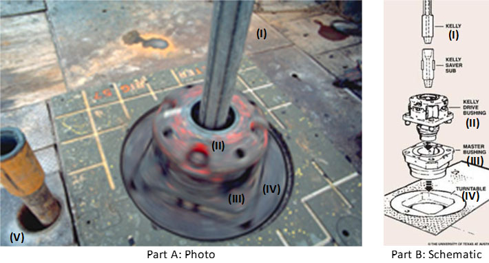
The rotary table is also called a turntable. Most rotary tables are chain driven. These chains resemble very large bicycle chains. The chains require constant oiling to prevent burning and seizing. Virtually all rotary tables are equipped with a rotary lock". Engaging the lock can either prevent the rotary from turning in one particular direction, or from turning at all. This is commonly used by crews in lieu of using a second pair of tongs to makeup or break out pipes. The rotary bushings are located at the center of the rotary table. These can generally be removed in two separate pieces to facilitate large items, e.g. drill bits, to pass through the rotary table. The large gap in the center of the rotary bushings is referred to as the "bowl" due to its appearance. The bowl is where the slips are set to hold up the drill string during connections and pipe trips as well as the point the drill string passes through the floor into the wellbore. The rotary bushings connect to the kelly bushings to actually induce the spin required for drilling.
Most recently manufactured rigs no longer feature rotary drives. These newer rigs have opted for top drive technology. In top drive, the drill string is turned by mechanisms located in the top drive that is attached to the blocks. There is no need for the swivel because the top drive does all the necessary actions. The top drive does not eliminate the kelly bar and the kelly bushings.

The square or hexagonal shaped steel pipe connecting the swivel to the drill string. The kelly moves through the rotary table and transmits torque to the drill string.
Square- or hexagonal-shaped steel pipe connecting the swivel to the drill pipe. NOTE The kelly moves through the rotary table and transmits torque to the drill stem.
Square or hexagonally shaped steel pipe connecting the swivel to the drill pipe that moves through the rotary table and transmits torque to the drill stem.
The square, hexagonal or other shaped steel pipe connecting the swivel to the drill pipe. The kelly moves through the kelly bushings, rotary table and rotates the drill string.
The uppermost component of the drill string; the kelly is an extra-heavy joint of pipe with flat or fluted sides that is free to move vertically through a “kelly bushing” in the rotary table; the kelly bushing imparts torque to the kelly and thereby the drill string is rotated.
The uppermost component of the drill string; the kelly is an extra-heavy joint of pipe with flat or fluted sides that is free to move vertically through a “kelly bushing” in the rotary table; the kelly bushing imparts torque to the kelly and thereby the drill string is rotated.
“Kelly” means a 3 or more sided shaped steel pipe connecting the swivel to the drill pipe. The kelly moves through the kelly bushing and the rotary table and transmits torque to the drill string. [Mich. Admin. Code R 408 (2013)].
The square or other shaped steel pipe connecting the swivel to the drill pipe. The kelly moves through the rotary table and transmits torque to the drill string.

Rotary drilling rigs for forming boreholes require a rotary table centrally positioned on the floor of the drilling rig. The rotary table has a rotating center which receives a kelly bushing therein which imparts rotation into a kelly. The kelly is free to slide within the bushing and has a string of drill pipe connected at the lower end and a swivel at the upper end thereof.
The rotating table center and kelly bushing usually have bolt heads, fastener heads, and various other protrusions as well as various different indentions formed thereon. This is especially so on the older rotary drilling rigs.
The roughnecks working on the confined floor of a drilling rig must handle cables, chains, ropes, water hoses, and various hand and power tools. All of this is carried out in an extremely small floor area and from time to time a tool will inadvertently fall onto the rotating table center and centrifugal force throws the tool outwardly where it may strike a workman.
Accordingly, it is advantageous and highly desirable to encapsulate the rotary table of a drilling rig so as to isolate this dangerous area from the workmen so that should one accidently drop anything on the rig floor, it cannot possibly be caught in the rotating center.
This invention relates to drilling rig safety equipment, and specifically to a guard for a rotary table and a kelly, such as may be found on a rotary drilling rig or a workover unit. The guard of this invention has a lower end in the form of a flat circular show member from which there upwardly extends a wall member. The upper end of the wall member terminates at a bearing means. The bearing means is spaced from and concentrically arranged respective to the shoe, and has a rotatable part which slidably receives a marginal length of the kelly therethrough. The rotating kelly rotates the rotatable part of the bearing while the remainder of the bearing means remains stationary. Hence, the guard encapsulates the most dangerous parts of the rotary table and kelly and prevents extraneous items from falling into contact therewith.
Another object of the present invention is to provide apparatus which will prevent extraneous members from contacting the rotating parts associated with a rotary table of a drilling rig or the like.
Another and still further object of this invention is to disclose and provide a safety structure which prevents contact of anything with the dangerous rotating parts of a rotary table.
A still further object of this invention is to provide a guard in the form of a non-rotating safety shield located about the rotating parts of a rotary table so that nothing can inadvertently contact the rotating parts.
This invention relates to a rotary table and kelly bushing guard for use in conjunction with a drilling rig, workover rig, or the like. In drilling boreholes, the massive rotary table, kelly, and kelly bushing are exposed in the center of the greatest activity of the drilling operation. From time to time, a roughneck will inadvertently catch a hose or chain or the like in the rotating mass, whereupon he often is violently thrown into the apparatus and fatally injured. Accordingly, the apparatus of the present invention isolates this dangerous mechanism from the surrounding area so that extraneous material cannot inadvertently come into contact therewith.
As seen in FIG. 1, a derrick floor 10 of a rotary drilling rig includes the non-rotating, circumferentially extending floor area 12 which overlies a rotary mechanism 14. The mechanism imparts rotation into a kelly bushing 16 by means of a drive sprocket 18 connected to the end of a pinion shaft of the rotary device. The kelly 20 is slidably received in a telescoping manner through the kelly bushing 16 in the usual manner, while drive mechanism 22 removably receives the kelly bushing 16 in the usual manner. As mechanism 16, 20, and 22 rotate respective to the fixed floor 12, there is a danger area 24" which must be avoided. There is always the grave danger that someone will somehow or another slip and fall into the danger area and thereby become severely injured.
In order to obviate this catastrophe, a rotary table and kelly bushing guard 24, made in accordance with the FIGS. 2--11 of the present invention, is slidably received about the kelly 20, thereby encapsulating the dangerous rotating mechanism of the drilling rig. The guard 24 includes an upper member in the form of bearing means 26 which slidably receives the rotating kelly therethrough. A heavy rubber shoe 28 forms a lower support member and is supported by the non-rotating area located outwardly of the rotary table, while a mid-portion 30 in the form of a circumferentially extending wall interconnects the bearing means 26 with the shoe 28.
As seen in FIGS. 6 and 8, together with other figures of the drawing, the bearing means includes Teflon rotatable member 36 within which there is formed an axial passageway 38 which slidably mates and rotates with the kelly 20. Bearing housing 40 is of annular configuration and preferably has the upper marginal end of ribs 32 molded therewithin. Washer 42 is split as indicated at 43 and is removably affixed to the fixed housing 40 by means of a plurality of fasteners 44 so that the rotating member 36 is captured in low friction relationship within the non-rotating member 40. This expedient enables the rotating member 36 to slidably receive and rotate with kelly 20 while non-rotating member 40 is held in a non-rotatable manner respective to the derrick floor and to the mid-portion 30.
Ribs 32 downwardly extend from the fixed upper housing member 40, as indicated by numeral 46. Member 36 is split into portions 48 and 50 so that the spaced fastener means 52 can be utilized for assembling the apparatus onto the kelly. Numeral 54 is the interface formed between the two members. The fasteners are received through apertures 56 and can include self-locking nuts and the like as may be desired.
In operation, fasteners 44 are removed to permit the two halves of washer 42 to be removed from the Teflon bearing assembly located at the upper end of the safety guard 24. Fasteners 52 are removed in order to split the rotating bearing member into halves 48 and 50 thereby facilitating assembly. The halves are placed about the kelly in the illustrated manner of FIG. 2. Stop member 25 preferably is a clamp device smaller in diameter than the pin or threaded male end of the kelly, and is tapered at the lower end to facilitate entrance through the kelly bushing and into the rat hole. The clamp holds the guard in the illustrated position of FIG. 3.
Bearing member 36 slidably engages the kelly for axial movement so that the kelly can continuously move in a downward direction as drilling progresses. When the kelly is lifted from the rotating table, the bearing means 36 of the protector device of the present invention engages the stop 25 and is lifted therewith in the manner of FIG. 3 so that another joint of drill pipe can be added to the drill string.
Hence, the rotating Teflon bearing axially slides respective to the kelly and captures the kelly therewithin so that it is rotated therewith. The heavy plastic guard cover 30 is nonrotatable and does not turn during kelly operation. The guard cover prevents one from inadvertently falling or stepping onto the rotary table, and furthermore prevents objects such as chains or hoses or ropes from catching the rotary table or kelly, and being wound thereabout, causing possible injury to adjacent personnel.
The heavy rubber shoe is located at the lower end of the safety guard. The shoe is provided with the illustrated small inside diameter 68 which forms a heel and tapers in an outward direction and terminates in a toe at large outside diameter 72. The bottom of the shoe is seen at 70. The marginal lower end of members 32 are imbedded within the shoe as noted by the numeral 74. This configuration forms a low profile so that a roughneck will not inadvertently stump his toe on the shoe. The present invention can be used in conjunction with any type of drilling or workover unit having a rotary table thereon. The non-rotating slidable safety guard of the present invention can be made of plastic, fiberglass, rubber, or metal, as shown in FIGS. 2 and 4. The safety guard can be left on the kelly and need not be removed for extended periods of time.
The center of the rotating bearing 36 can be made square as illustrated or hexagon to accommodate a hex shaped kelly as well as being made in other configurations for accommodating any other type kelly.
The present invention relates in general to the art of drilling oil and gas wells and, more particularly, to the measurement of rotary torque and RPM for oil and gas drilling rigs.
In the drilling of oil and gas wells with rotary rigs, and, in particular, the drilling of deep wells, the drill pipe is subjected to considerable stress. The stress is imposed by the weight of the drill string, by the resistance of the strata to the rotation of the drill pipe and to the cutting action of the drill bit in the different strata. Care must be taken to control the amount of torque imposed on the drill string, otherwise twist-offs may occur which would result in expensive fishing jobs to retrieve the last portion of the drill string.
The measurement of rotary torque is used to observe pipe sticking, indicate bit wear and optimize drilling. The counting of total revolutions of the drill string can give wear-life data to help prevent failure while drilling. RPM, used with rotary torque, weight on bit and rate of penetration, can be used to calculate factors that give valuable drilling data. The present invention provides a system for the transmission of rotary torque and real time revolutions from the rotary table/Kelly combination of an oilfield or other rotary drilling rig. Real time revolutions allow the RPM to be calculated.
The prior art measurement of rotary torque and revolving speed utilizes two, usually separate, transducer systems. Rotations are sensed by proximity switches which are closed each revolution. This method is commonly used, however, the switches often get in the way of the driller. Another commonly used method is to use a take-off point in the rotary chain drive and an electrical tachometer-generator. This method has the drawbacks of having to scale the output voltage and/or frequency in order to determine true revolutions. Either method is commonly used by wiring the transducer to the readout mechanism. Rotary torque is often measured by means of tension measurement in the rotary drive chain, accessible only from beneath the rig floor and rotary table.
In U.S. Pat. No. 3,664,184 to Norman D. Dyer, patented May 23, 1972, a rotary torque indicator for well drilling apparatus is shown and described as follows. The device is used to indicate torque applied by the rotary table to the drill string during drilling of oil and gas wells. An intermediate adapter between the Kelly bushing and the rotary table in one embodiment has two parts. The lower part of the adapter includes a standard male square drive that fits into the square drive of the rotary table, and is thus rotated by the rotary table. The upper part of the adapter includes a female square drive arranged to receive the male square drive on the Kelly. The Kelly transmits torque from the adapter assembly to the drill pipe. The upper part is connected to the lower part by either hydraulic cylinders or by linkage with strain gauge. The upper part rotates with the lower part, but is moveable relative thereto to indicate relative torque between the upper and lower parts. An R.F. transmitter connected to the hydraulic cylinder or strain gauge provides a torque signal to a remote R.F. receiver. An alternative embodiment has a unitized adapter assembly. Still another alternative embodiment uses a torque sensor and R.F. transmitter directly on the Kelly drive bushing without utilization of an intermediate bushing.
In U.S. Pat. No. 3,691,825 to Norman D. Dyer, patented Sept. 19, 1972, a rotary torque indicator for well drilling apparatus is shown and described as follows. This device is used to indicate torque applied by the rotary table to the drill string during drilling of oil and gas wells. An intermediate adapter between the Kelly bushing and the rotary table in one embodiment has two parts. The lower part of the adapter includes a standard male square drive that fits into the square drive of the rotary table, and is thus rotated by the rotary table. The upper part of the adapter includes a female square drive arranged to receive the male square drive on the Kelly. The Kelly transmits torque from the adapter assembly to the drill pipe. The upper part is connected to the lower part by either hydraulic cylinders or by linkage with a strain gauge. The upper part rotates with the lower part, but is moveable relative thereto to indicate relative torque between the upper and lower parts. An R.F. transmitter connected to the hydraulic cylinder or strain gauge provides a torque signal to a remote R.F. receiver. An alternative embodiment has a unitized adapter assembly. Still another alternative embodiment uses a torque sensor and R.F. transmitter directly on the Kelly drive bushing without utilization of an intermediate bushing.
The present invention provides a system for measuring the rotary torque and RPM of a rotary drill string. An intermediate adapter is positioned between the Kelly and the rotary table. A strain gauge is attached to the intermediate adapter to measure torsional deformation and provide an indication of rotary torque. Transmission of torque data is accomplished by radio frequency transmission utilizing a transmitter on the intermediate adapter. A receiver is mounted to the side of the drill rig floor to receive and demodulate the torque signal. The intermediate adapter is rotating at the same rate as the drill string. Detection of revolutions of the drill string is accomplished at the edge of the drill rig platform or elsewhere with a stationary sensor which doubles as the torque receiver. A highly directional torque transmitter antenna mounted on the adapter is used with the major lobe parallel to the rig floor and perpendicular to the drill pipe. By detecting the envelope of the radio frequency field strength, each rotation is marked by a peak. This enables continuous torque and RPM monitoring. The foregoing and other features and advantages of the present invention will become apparent from a consideration of the following detailed description of the invention when taken in conjunction with the accompanying drawings.
Referring now to the drawings and, in particular, to FIG. 1, an embodiment of the present invention is illustrated in conjunction with an oil well drilling rig 10 and a rotary drill string 11 used in an oil well drilling operation. A well bore 12 is shown having a casing 13. The rotary drill string 11 is provided with a drill bit 14 at its lower end. The drill string 11 is rotated by a rotary table 15 mounted in the derrick 16. Drilling mud is pumped from a mud pit 17 through line 18 by pump 19. The mud is pumped into the drill string 11 and is discharged out of the bit 14 into the well bore 12. The mud continues upward in the well bore 12 and is returned from the top of the casing 13 by a mud flowline 20 to the mud pit 17. An openable and closeable blowout preventer or rotary drill head of any suitable conventional type is provided at the upper end of the casing 13.
The drill string 11 is attached to the lower end of the drive Kelly 21. An intermediate adapter 22 is positioned between the Kelly 21 and the rotary table 15. Enlarged views of the intermediate adapter 22 are shown in FIGS. 2 and 3. The adapter 22 rotates with the drill string/Kelly combination and transmits all of the torque from the rotary table 15 to the Kelly 21. The mechanical portion is a one-piece adapter with one end 23 that fits into the square rotary table drive bushing. The other end 24 accepts the square shoulder of the Kelly drive. Between the two ends is a tubular section 25 that allows the Kelly 21 to pass through. The material and thickness of this tubular section 25 must be chosen so that the torque range transmitted through the adapter 22 is sufficient to achieve a measurable elastic strain deformation yet be totally safe from structural failure. This type of Kelly adapter is described in U.S. Pat. Nos. 3,664,184 and 3,691,825 by Norman Dyer.
The transmission of the torque and RPM information from the adapter 22 to a receiver 27 is illustrated in FIG. 4. A top view of the floor of the drilling rig 16 is illustrated. The analog strain value is converted to a frequency and the frequency is used to f-m modulate the carrier frequency. The radio frequency chosen is based on interference, regulations and acceptable antenna dimensions. The transmitter may be low powered since the usual distance to be transmitted is less than 100 feet. The receiver 27 mounted to the side of the drill rig floor will receive and demodulate the torque and RPM signal. Since the adapter 22 is rotating at the same rate as the drill string and rotary table, simultaneous torque detection and revolutions of the rotary table are obtained. The revolutions may be detected at the edge of the drill rig platform with a stationary sensor which doubles as the torque receiver. A highly directional torque transmitter antenna is mounted on the adapter with the major lobe lying parallel to the rig floor and perpendicular to the drill pipe. By detecting the envelope of the R.F. (radio frequency) field strength, each rotation is marked by a peak. This enables continuous torque and RPM monitoring.
FIG. 6 shows the associated receiver for the transmitter of FIG. 5. The operation is as follows: Battery power source 31 powers all active components of the torque transmitter of FIG. 5. Load cell 28, which may also be a strain bridge or other device to determine torque as described in the Dyer patent, is amplified by amplifier 52, which may be commercially available or built from integrated circuit op amps such as Fairchild μA725. A frequency-to-voltage converter 29, such as may be built with Raytheon Semiconductor"s RC4151 converts the torque voltage signal to an equivalent frequency, i.e., in the range of 0-10,000 Hertz. The 217 MHz FM transmitter 34, similar in function to "FM Wireless Mike", Markus, Sourcebook of Electronic Circuits 1968, p. 802 is used to transmit the frequency signal 33 through the directional antenna 36. This antenna is arranged so that one or more of its directional lobes lie in a plane parallel to the rig floor and perpendicular to the drill string. In this manner, the lobes will sweep over the rig floor once each revolution of the Kelly/drill string assembly. An example of a one-lobe antenna is the well-known dish-type antenna; a simple horizontal centerfed dipole has two lobes.
The block diagram of the receiver is shown in FIG. 6. Its directional antenna 38 is pointed toward the drill string/Kelly assembly. FM discriminator/demodulator 47 converts the torque data back to a frequency; then frequency-to-voltage converter 48 (utilizing an RC4151) converts the frequency to analog torque at line 49. Alternately, a counter and time base can digitize torque. Envelope detector 40, which consists of a semiconductor diode 41, filter capacitor 42, and decay resistor 43, follows the envelope of the R.F. signal giving an indication of strength. The RC time constant should be larger than the modulation period, but much less than the fastest expected rotating period of the Kelly. A threshold detector 45, which may consist of an integrated circuit op amp wired as a D.C. comparator, can detect each R.F. signal strength period. For good noise immunity, a Schmitt trigger should be used, and the trigger level set by the relative average signal strength. If the Kelly transmitter antenna has more than one lobe, then there will be one output pulse per lobe per revolution. The combination of FIGS. 5 and 6 provide a system which receives torque data continuously, and has a logic output at every revolution.
Another embodiment will be described that has the advantages of requiring less battery energy in the Kelly electronics. This reduces either the battery size or the required service interval. The block diagram for this system is shown in FIGS. 7 and 8 showing the Kelly package and the fixed rig-mounted package. Antennas 52 and 67 are highly directional one lobe antennas, aimed in the same manner as the previously described embodiment so that they achieve maximum gain relative to each other once per revolution. The torque receiver is shown in FIG. 8. It contains a transmitter at a different frequency (i.e. 173.2 MHz) than the torque data transmitter. It is continuously modulated in an amplitude modulation scheme by a signal generator 77, driving AM transmitter 79. A diplexer 68 allows antenna 67 to both receive torque data through line 69 and transmit trigger signal through line 80 at 173.2 MHz.
The Kelly unit has a low power receiver 55 which is tuned to 173.2 MHz and has a band-pass filter tuned to the periodic generator 77 in the data receiver"s transmitter. When the 173.2 MHz signal exceeds a threshold, the receiver "switches", firing a one-shot unit 57, this switching action may be accomplished by a preset trigger threshold or by a dynamic threshold which follows the average level of the input R.F. signal and thus discriminates against noise.
When the FM receiver 70 shown in FIG. 8 detects a signal, two things happen. The receiver AGC (automatic gain control) changes to indicate the relative field strength. This action may be "cleaned" to a good logic signal by Schmitt trigger 72, similar to Motorola Semiconductors MC14093. Thus since there is data transmission once each revolution of the Kelly, the antennas couple once and there is one 217 MHz transmission. Thus each logic output of Schmitt trigger 72 indicates one revolution.
The data is derived as a frequency signal proportional to torque by the receiver"s FM discriminator. An F-V converter 75 converts it to an analog signal, or a digital counter and time base can convert it easily to a digital value. Since the value only exists while being transmitted, a memory device is required to hold the last value. This may be a sample-and-hold device 82 triggered by the revolution output on line 73 to hold the data after that. A digital memory may be used and will have more ideal memory. Wherever a revolution signal 73 is detected, the memory should be refreshed by the current R.F. torque data being transmitted from the Kelly.
The 173.2 MHz R.F. interrogation signal is on continuously. The directional Kelly antenna sees a peak every revolution when the antenna radiation patterns couple. The switch receiver puts out a series of pulses, one for each peak in the interrogation signal. Finally, the 217 MHz bursts are seen by the torque receiver. The length of the burst is long enough so that the V-F unit 63 can settle to a specific accuracy, but short enough to conserve battery power and only be on while the antennas remain coupled by their position.
It would also be possible to provide an antenna system mounted in the Kelly so that its phase angle would be constantly changing relative to the receiver. The receiver would monitor the phase cancellations and reinforcements and determine the occurrence of each revolution. It is also possible to monitor revolutions only, by not modulating the R.F. signal from the Kelly assembly. In this case, the Kelly adapter is not necessary and the electronics (transmitter and antenna) may be mounted directly to the Kelly or Kelly bushing. From indications of each rotation, conventional rate meters may be used to indicate rotary rate in RPM. Such meters may be a SWACO Div. of Dresser Industries Combination Pump Stroke Rate Meter/Counter, which has the capability of determining RPM of an input signal closure rate.
Rotary drilling uses a sharp, rotating drill bit to dig down through the Earth’s crust. Much like a common hand-held drill, the spinning of the drill bit allows for penetration of even the hardest rock.
The idea of using a rotary drill bit is not new. Archeological records show that as early as 3000 B.C., the Egyptians may have been using a similar technique. Leonardo Di Vinci, as early as 1500, developed a design for a rotary drilling mechanism that bears much resemblance to technology used today. Despite these precursors, rotary drilling did not rise in use or popularity until the early 1900s.
Although rotary drilling techniques had been patented as early as 1833, most of these early attempts at rotary drilling consisted of little more than a mule, attached to a drilling device, walking in a circle. It was the success of the efforts of Anthony Lucas and Patillo Higgins in drilling their 1901 Spindletop well in Texas that catapulted rotary drilling to the forefront of petroleum drilling technology.
While the concept for rotary drilling – using a sharp, spinning drill bit to delve into rock – is quite simple, the actual mechanics of modern rigs are quite complicated. In addition, technology advances so rapidly that new innovations are being introduced constantly.
The basic rotary drilling system consists of four groups of components – the prime movers, hoisting equipment, rotating equipment and circulating equipment – that all combine to make rotary drilling possible.
The prime movers in a rotary drilling rig are those pieces of equipment that provide the power to the entire rig. Steam engines provided the power to the early drill rigs. Gas and diesel engines became the norm after World War II. Recently, while diesel engines still compose the majority of power sources on rotary rigs, other types of engines also are in use; more so in the oil and gas industry than in the water well sector. Natural gas or gasoline engines commonly are used, as are natural gas- or gasoline-powered reciprocating turbines, which generate electricity on-site. The resulting electricity is used to power the rig itself. The energy from these prime movers is used to power the rotary equipment, the hoisting equipment and the circulating equipment, and, on large rigs, may be used as well to provide incidental lighting, water and compression requirements not directly associated with drilling.
The hoisting equipment on a rotary rig consists of the tools used to raise and lower whatever other equipment may go into or come out of the well. The most visible part of the hoisting equipment is the derrick, which serves as a support for the cables (drilling lines) and pulleys (drawworks) that serve to lower or raise the equipment in the well.
For instance, in rotary drilling, the wells are made with long strings of drill pipe extending from the surface down to the drill bit. If a drill bit needs to be changed, either due to wear and tear or a change in the subsurface rock, the whole string of pipe must be raised to the surface.
The rotating equipment on a rotary drilling rig consists of the components that actually serve to rotate the drill bit, which, in turn, sends the hole deeper and deeper into the ground. The rotating equipment consists of a number of different parts, all of which contribute to transferring power from the prime mover to the drill bit itself. The prime mover supplies power to the rotary, which is the device that turns the drill pipe, which, in turn, is attached to the drill bit. A component called the swivel, which is attached to the hoisting equipment, carries the entire weight of the drill string, but allows it to rotate freely.
Below the drill pipe are drill collars, which are heavier, thicker and stronger than normal drill pipe. The drill collars help to add weight to the drill string, right above the bit, to ensure there is enough downward pressure to allow the bit to drill through hard rock. The number and nature of the drill collars on any particular rotary rig can be altered depending on the down-hole conditions experienced while drilling.
The final component of rotary drilling consists of the circulating system. There are a number of main objectives of this system, including cooling and lubricating the drill bit, removing debris and cuttings, and coating the walls of the well with a mud type-cake. The circulating system consists of drilling fluid, which is circulated down through the well hole throughout the drilling process.
Rotary drilling, as opposed to percussion drilling, cuts by rotating a bit at the bottom of the hole. In addition to rotation, downward pressure must be exerted and continued as the bit cuts it way through the formation.
Part of the art of rotary drilling is to match the bit type and pull-down pressure with the formation, and the use of drilling fluids to maintain circulation to keep the hole clear of cuttings and the bit lubricated and cool. A rotating table turns the drill string via a kelly bar passing through the table and attached to the top joint of the drill string.
When beginning a new hole, and oftentimes during drilling operations, pull-down pressure from the drill rig is applied. This pull-down force is achieved by a screw, cable or chain arrangement, or by hydraulic motors. Hydraulically powered pull-down actions usually are found on more recently manufactured drill rigs, with screw, cable and chain pull-down arrangements more commonly found on older rotary rigs.
The driller controls the pull-down pressure and, thus, the speed of penetration. It must be noted that part of the art of rotary drilling is the matching of pull-down pressure to the formation. Excessive pull-down pressure can damage drill bits, drill pipe and the trueness of the borehole. Thus, applying more pull-down pressure is not always the best drilling practice.
The kelly is a primary link between the drilling rig’s surface equipment and the bit, and is therefore a critical component of the rotary system. Although top drive systems have replaced kelly/rotary table combinations on many rigs, some knowledge of their manufacture and operation is useful.
Their angled surfaces, or drive flats, are designed to fit into a drive roller assembly on the kelly bushing, so that as the rotary table turns to the right, the kelly turns with it. To allow for normal right-hand rotation of the drill string, kellys have right-hand threads on their bottom connections and left-hand threads on their top connections.
The American Petroleum Institute has established manufacturing and design standards for kellys, and has included them in the follwoing publications:API RP 7G, Recommended Practice for Drill Stem Design and Operating Limits.
For a kelly to be efficient in turning the drill string, the clearance between its drive flat surfaces and the rollers in the kelly bushing must be kept to a minimum. Kellys most often wear out due to a rounding-off of the drive corners, as shown in Figure 1 (new kelly with new drive assembly) and Figure 2 (worn kelly with worn drive assembly).
For minimal rounding, there must be a close fit between the kelly and the roller assembly, with the rollers fitting the largest spot on the kelly flats. Manufacturing techniques and rig operating practices play important roles in determining this fit.
Both square and hexagonal kellys are manufactured either from bars with an “as-forged” drive section, or from bars with fully-machined drive sections. Forged kellys are cheaper to manufacture. But machined kellys tend to last longer because:Unlike forged kellys, machined kellys are not subject to the metallurgical process of decarburization, which leaves a relatively soft layer of material on the drive surface that can accelerate the rounding process and increase the potential for fatigue cracks;
To minimize rounding, rig personnel should follow these guidelines (Brinegar, 1977):Always use new drive-bushing roller assemblies to break in a new kelly.
Frequently inspect and periodically replace drive assemblies to ensure that clearance and contact angle between the kelly and the rollers is held to a minimum;
Fatigue failures are seldom a problem with kellys because of the high-quality steels used in their manufacture. Nevertheless, kellys should be regularly inspected for cracks and other signs of wear, particularly within the threaded connections, in the areas where the flats join the upper and lower upsets and in the center of the drive section.
In general, the stress level for a given tensile load is less in the drive section of a hexagonal kelly than in the drive section of a square kelly of comparable size. Hexagonal kellys are thus likely to last longer than square kellys before failing under a given bending load.
Kellys can become crooked or bent due to improper handling. Examples of mishandling include dropping the kelly, misaligning it in the rathole and thereby exerting a side pull, using poor tie-down practices during rig moves, not using the kelly scabbard and improper loading or unloading techniques. Depending on where a bend is located, it may cause fatigue damage not only to the kelly but to the rest of the drill string, and can also result in uneven wear on the kelly bushing.
Unusual side motions or swaying of the swivel are good indicators of a crooked kelly. A good field service shop has equipment for straightening bent kellys, making this an easily-corrected problem.
A kelly saver subshould always be run between the kelly and the top joint of drill pipe. This protects the kelly’s lower connection threads from wear, as joints of drill pipe are continually made up and broken out. A saver sub is much less expensive and much easier to replace than the kelly itself, and it can also be equipped with a rubber protector to help keep the kelly centralized and to protect the top joint of casing against wear.
A kelly cock is a valve installed above or below the kelly, which prevents fluid from escaping through the drill string if the well should begin to flow or “kick.” As an extra well control precaution, an upper kelly cock (having left-hand threads) should be installed directly above the kelly, while a lower kelly cock (having right-hand threads) should be installed below the kelly. Installing two kelly cocks ensures that at least one of them is always accessible, regardless of the kelly’s position.
Automatic check valves, designed to close when the mud pumps are shut off, are also available, and can be installed below the kelly to prevent mud from spilling onto the rig floor during connections.

Wedge-shaped pieces of metal with teeth or other gripping elements that are used to prevent pipe from slipping down into the hole or to hold pipe in place. Rotary slips fit around the drill pipe and wedge against the master bushing to support the pipe. Power slips are pneumatically or hydraulically actuated devices that allow the crew to dispense with the manual handling of slips when making a connection. Packers and other down hole equipment are secured in position by slips that engage the pipe by action directed at the surface.†
The principal component of a rotary, or rotary machine, used to turn the drill stem and support the drilling assembly. It has a beveled gear arrangement to create the rotational motion and an opening into which bushings are fitted to drive and support the drilling assembly.
The heavy square or hexagonal steel member suspended from the swivel through the rotary table. It is connected to the topmost joint of drill pipe to turn the drill stem as the rotary table turns.†
A hole in the rig floor 30 to 35 feet deep, lined with casing that projects above the floor. The kelly is placed in the rathole when hoisting operations are in progress.†
The top drive rotates the drill string end bit without the use of a kelly and rotary table. The top drive is operated from a control console on the rig floor.†
The large wrenches used for turning when making up or breaking out drill pipe, casing, tubing, or other pipe; variously called casing tongs, rotary tongs, and so forth according to the specific use. Power tongs are pneumatically or hydraulically operated tools that spin the pipe up and, in some instances, apply the final makeup torque.†
The cutting or boring element used in drilling oil and gas wells. Most bits used in rotary drilling are roller-cone bits. The bit consists of the cutting elements and the circulating element. The circulating element permits the passage of drilling fluid and uses the hydraulic force of the fluid stream to improve drilling rates.†

The cutting or boring element used in drilling oil and gas wells. Most bits used in rotary drilling are roller-cone bits. The bit consists of the cutting elements and the circulating element. The circulating element permits the passage of drilling fluid and uses the hydraulic force of the fluid stream to improve drilling rates.†
The heavy square or hexagonal steel member suspended from the swivel through the rotary table. It is connected to the topmost joint of drill pipe to turn the drill stem as the rotary table turns.†
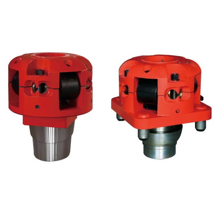
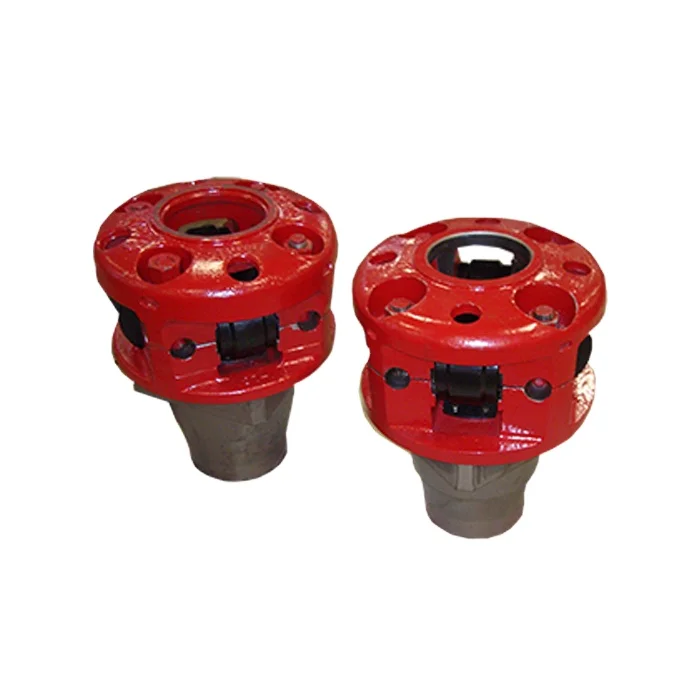
A device fitted to the rotary table through which the kelly passes. It is the means by which the torque of the rotary table is transmitted to the kelly and to the drill stem. Also called the drive bushing.†
A portable derrick capable of being erected as a unit, as distinguished from a standard derrick, which cannot be raised to a working position as a unit.†
A hole in the rig floor 30 to 35 feet deep, lined with casing that projects above the floor. The kelly is placed in the rathole when hoisting operations are in progress.†
The hose on a rotary drilling rig that conducts the drilling fluid from the mud pump and standpipe to the swivel and kelly; also called the mud hose or the kelly hose.†
The principal component of a rotary, or rotary machine, used to turn the drill stem and support the drilling assembly. It has a beveled gear arrangement to create the rotational motion and an opening into which bushings are fitted to drive and support the drilling assembly.
A series of trays with sieves or screens that vibrate to remove cuttings from circulating fluid in rotary drilling operations. The size of the openings in the sieve is selected to match the size of the solids in the drilling fluid and the anticipated size of cuttings. Also called a shaker.†
Wedge-shaped pieces of metal with teeth or other gripping elements that are used to prevent pipe from slipping down into the hole or to hold pipe in place. Rotary slips fit around the drill pipe and wedge against the master bushing to support the pipe. Power slips are pneumatically or hydraulically actuated devices that allow the crew to dispense with the manual handling of slips when making a connection. Packers and other down hole equipment are secured in position by slips that engage the pipe by action directed at the surface.†
A relatively short length of chain attached to the tong pull chain on the manual tongs used to make up drill pipe. The spinning chain is attached to the pull chain so that a crew member can wrap the spinning chain several times around the tool joint box of a joint of drill pipe suspended in the rotary table. After crew members stab the pin of another tool joint into the box end, one of them then grasps the end of the spinning chain and with a rapid upward motion of the wrist "throws the spinning chain"-that is, causes it to unwrap from the box and coil upward onto the body of the joint stabbed into the box. The driller then actuates the makeup cathead to pull the chain off of the pipe body, which causes the pipe to spin and thus the pin threads to spin into the box.†
A vertical pipe rising along the side of the derrick or mast. It joins the discharge line leading from the mud pump to the rotary hose and through which mud is pumped going into the hole.†
A rotary tool that is hung from the rotary hook and traveling block to suspend and permit free rotation of the drill stem. It also provides a connection for the rotary hose and a passageway for the flow of drilling fluid into the drill stem.†
The large wrenches used for turning when making up or breaking out drill pipe, casing, tubing, or other pipe; variously called casing tongs, rotary tongs, and so forth according to the specific use. Power tongs are pneumatically or hydraulically operated tools that spin the pipe up and, in some instances, apply the final makeup torque.†
The top drive rotates the drill string end bit without the use of a kelly and rotary table. The top drive is operated from a control console on the rig floor.†

5-1. Mud Rotary Drilling. Rotary drilling with mud is the most widely used method for water-well construction. A rotary drill rig has three functions: rotating the drill string, hoisting the drill string, and circulating the drilling fluid. A bit is rotated against the formation while mud is pumped down the drill pipe, through ports in the bit, and back to the ground surface through the annulus between the drill pipe and the borehole wall. (Table 5-1 shows the relative performance of drilling methods in various geologic formations.) Drill cuttings rise to the ground surface in the drilling fluid. Rotary drilling is sometimes called mud rotary drilling. Drill pipes or rods are joined to a bit to form the drill string. The drill pipe is the link transmitting torque from the rig to the bit, and the pipe carries the drilling fluid down the hole.
a. Rotary Rigs. Rotary rigs vary in design. Drilling rigs are truck- or trailer-mounted and are powered by an on-board engine or by a PTO from the truck transmission. Power is delivered to the various components through hydraulic pumps and motors or through mechanical transmissions and clutches and geared on roller-chain drives. Many drill rigs may use both mechanical and hydraulic drives. Torque is applied to the drill string, which rotates by using three basic designs--rotary table, top head, and quill-and-drive bar. Military drilling machines use rotary table drives.(1) Rotary Table. The rotary table is a rotating platform that transmits torque to the drill rod through the kelly. The kelly, which is attached to the mud swivel, is the uppermost section of the drill string that passes through the rotary table. The drill string may be square, hexagonal, or round with grooves or flukes on the outside wall. The drive kelly bar slides through the rotary table while rotating. By removing the kelly bar, you can add drill pipe and work the pipe through the open hole in the rotary table. The rotary table normally is a mechanical, positive drive mechanism.
(2) Top Head. The top-head drive uses a power swivel. Torque is applied at the top of the drill string. The top-head mechanism moves down along the rig mast as the boring is advanced and is raised to the top of the mast to add a length of drill pipe. Top-head-drive drill rigs do not use a kelly bar. Most top-head drives are powered by hydraulic motors capable of variable speeds rather than positive constant rotation.
(3) Feed Drive. Rotary rigs are equipped with a mechanism to apply a downward thrust to the drill string. This mechanism is called a pulldown or feed drive.
Generally, two roller chains apply the thrust for rotary tables. The chains are attached to the kelly swivel and extended over sprockets at the top of the mast and under the rotary table. On older rigs, the sprockets under the rotary table are powered mechanically through a PTO and clutch. The pulldown chains on modem drill rigs are powered by a hydraulic motor, which provides better thrust control.
The thrust mechanism on most top-head rigs is a pair of roller chains consisting of two chain sections. One end of each section is attached to the swivel at the top of the kelly bar. The other ends are dead-headed to the top and bottom of the mast. Sprockets at the top and bottom of the mast act as idlers. Chains are powered in either direction by hydraulic rams. These rams apply thrust and are used in a hold-back mode to reduce the bit load of the weight due to the drill string. This chain mechanism is also the main hoist for lifting the drill string.
(4) Mud Pump. A mud pump (Figure 5-1) on a rotary drill is usually a positive-displacement, double-acting piston pump with capacities ranging from one to several hundred GPM at pressures up to several hundred psi. Power may be provided through a mechanical PTO and clutch, with or without a separate transmission. Power may also be provided by a separate engine or a hydraulic or air motor. Other types of pumps are often used successfully, but their limited pressure capacity may jeopardize the success of the drilling operation. Most well-drilling machines have dual piston, double-acting, positive-displacement mud pumps. Pump capacity (volume and pressure) can limit the effective depth of a drilling operation. The horsepower required to drive a mud pump often exceeds the power required to hoist and rotate the drill string.
b. Drill Bits. See Table 5-2 for recommended rotating speeds for all sizes and types of bits in various formations. See Figure 5-2 for bit selection. Appendix E discusses characteristics and maintenance for drill bits.
c. Rotary Operation. Standard rotary drilling involves the bit rotating against the formation. Drilling fluid is pumped through the drill string and face of the drill bit and backup the annulus to the surface. The rotary action of the bit loosens the material, while the drilling fluid cools and lubricates the drill pipe and bit and carries cuttings to the surface. The drilling fluid is under high hydrostatic pressure and supports the wall of the borehole against caving. The properties of the drilling fluid are important to the drilling operation. Well drillers must have knowledge of drilling fluids and their use for successful rotary drilling. Drillers must also know about drilling-fluid additives used to prevent problems in drilling. Preventing drilling problems, such as an unstable borehole wall or a stuck tool, is easier than fixing the problem after it occurs. See paragraph 5-1e for information on drilling fluids.
Before drilling with mud, build a mud pit. The pit may be either a portable pit or an excavated mud pit. The decision depends on the hole depth and the alternatives available. See paragraph 5-1e(9) for more information on mud pits.
d. Variables. Bit design, weight on bit, rotation speed, fluid consistency, and cumulation pressure and velocity affect rotary drilling. Experience helps the driller handle unique problems and conditions. Continue to experiment wherever you drill to develop the best drilling procedure. Before starting the hole, plumb the kelly to provide a straight hole (Figure 5-3).
(2) Weight on Bit. Adding weight on the bit increases the torque required for rotation. Too much weight can cause excessive penetration and produce cuttings that are too large and heavy. Large cuttings are difficult to wash out and may cause gumming and premature failure of the bit. Insufficient weight reduces or stops penetration and can produce fine cuttings. In cohesive soils, fine cuttings may thicken the drilling fluid and fail to settle in the mud pit. How weight is applied can also cause serious alignment problems and difficulty in well construction. Rotary-drilled boreholes spiral slightly and are seldom straight. Once spindling occurs, weight added by pulling down with the drill rig bends the string and magnifies the deviation. You should never use the chain pulldown to advance the hole beyond the first run (20 feet). Ideally, keep the drill string in tension. Add drill collars (heavy wall drill steel) at the bottom just above the bit. See Table 5-3 for drill collar weights.
Bit weight required to cut rock depends on the design of the bit and the strength of the rock. Roller bits need a minimum of 2,000 psi of bit diameter for soft rock and shale and a maximum of 6,000 psi of bit diameter for hard rock. Before drilling, add drill collars instead of drill pipe until the load is sufficient for reasonable cutting. As you dig deeper and add drill pipe, you may have to hold back on the drill string. See Table 5-4 for weight on bit and rotary speed.
e. Drilling Fluids. Drilling fluid is circulated in rotary drilling to cool, clean, and lubricate the drill string, to flush cuttings from the hole, and to stabilize the borehole wall. Water is the basic fluid and is satisfactory for lubricating and cooling the tools. However, water has limited abilities to carry cuttings and stabilize the borehole wall. Many drilling fluid additives are prepared and formulated for various purposes. Polymer fluids and water-based clay fluids (muds) are the primary additives used in water-well drilling. Table 5-5 lists drilling fluids.
Therefore, if you keep the borehole clean with the fluid as you drill, you also cool and lubricate. This is true with clay muds and polymer fluids. Clay muds are colloidal suspensions. Solutions are chemical mixtures that cannot be separated by simple filtering. Suspensions are physical mixtures of solids and liquid that can be separated by filtering. This distinction underlies the difference in behavior between drilling polymers (solutions) and drilling muds (suspensions). You can mix natural clays with water for use as a drilling mud. Drillers often use water in shallow clayey strata and depend on the formation clay to produce a suitable mud. Natural-clay mud properties are marginal for good water-well drilling.
Polymer drilling fluids can break down viscosity. Without treatment, the viscosity of some polymers (Revert) completely breaks down in one to six days depending mainly on temperature. You can correct this by adding chlorine. Revert requires Fast Break; E-Z Mud needs sodium hypochlorite at a ratio of 2 quarts for every 100 gallons of water. Other polymers, such as E-Z Mud and Poly-Sal, maintain their viscosity for long periods of time since natural breakdown is not significant. Table 5-6 lists additives for drilling fluids.
The density of the drill fluid serves other purposes in rotary drilling. Heavy fluids can control (hold down) formation pressures encountered in drilling. You can build heavy mud by adding a weighing material such as ground barite (specific gravity 4.25). Prepare drilling mud in excess of 20 pounds per gallon by using barite. First, mix bentonite and water to build viscosity. Then, add finely ground barite so the mud will hold the barite in suspension. Use heavy drilling mud only when absolutely necessary to control pressures since the muds have disadvantages. High-density mud increases pressure on the formation by the weight of the fluid column. Figure 5-7 shows the nomograph for determining the hydrostatic head produced by drilling fluids. The increased pressure is further increased by the pump pressure required to mobilize the fluid in circulation. The increased pressure can cause formation damage and loss of circulation. In formations that are strong enough to withstand the pressures without being damaged, the drilling operation can still suffer.
A thin, highly impermeable filter cake bonds well to the wall and provides a surface for the hydrostatic pressures to act against to support the wall. Filtrate loss into the formation can account for significant fluid loss, if the consistency of the drilling mud is not good. Good consistency does not necessarily mean thick; it has to do with the bentonite content and the quality of falter cake. If a permeable formation is encountered with pore spaces too large to be plugged by the fine bentonite particles, the drilling mud will enter the formation. That mud loss can take the entire output of the mud pump. The drill cuttings being carried up the annulus can sometimes be beneficial. The cuttings are coarser than the bentonite particles and may help bridge across formation pores. If you use this technique, maintain the normal drilling rate to supply the cuttings. Slow down the pumping rate to reduce pressure on the formation while bridging the open spaces. With sufficient bridging, a suitable filter cake follows, circulation is regained, and normal drilling operations are resumed.
(9) Mud Pits. Rotary chilling preparation is the design and excavation of an in-ground mud pit or installation of a portable mud pit and the mixing of the drilling fluid. For standard drilling operations that use well-completion kits, well depths could range from 600 to 1,500 feet. For wells up to 600 feet using the 600-foot WDS, use portable mud pits. For wells over 600 feet, use dug mud pits. In either case, you will have to clean cuttings from the pits as drilling progresses. Design considerations include the anticipated depth and diameter of the drill hole, since the material cuttings from the hole will be deposited in the mud pits.
Mud pits are part of the circulating system for mixing and storing drilling fluid and for settling cuttings. The ground slope will affect site layout. Pit design can enhance pit performance. Most drillers agree that using multiple pits is best when dropping drill cuttings from the fluid. The volume of the pit should be one and one-half to three times the volume of the hole. This will provide fluid to fill the hole and an excess volume to allow stilling and settlement or processing before returning to the drill string. A volume of three times the hole volume will minimize drilling-fluid and mud-pit maintenance. Figure 5-9 shows a mud pit that is prepared on-site. Figure 5-10 shows a portable mud pit.
f. Rotary Drilling Problems. Some problems in rotary drilling are minor and others are serious and can result in failure to complete a hole or even loss of equipment. Many serious problems start minor but can become serious if not recognized or handled properly. For example, in a loose sand zone, the borehole walls can slough and cause drilling fluid loss. By reducing or increasing fluid velocity, you can stabilize the wall and regain fluid circulation. However, if you do not recognize the condition and you continue drilling, the wall will slough and create a cavity. The cuttings lose velocity, become suspended in the cavity, and tend to fall back into the hole when you add a rod. This action can result in the rods or the bit becoming stuck in the hole. Other problems can result from subtle changes in geology, imbalances in the drilling operation, or equipment failure.(1) Lost Circulation. Lost circulation refers to a loss in volume of drilling fluid returning to the surface. The implication is that some fluid pumped down the drill pipe is entering the formations. The mud pit will lower, since some of the mud is used in forming a mud cake on the borehole wall; however, increased lowering can indicate circulation loss. Losses can occur through open-graded sand or gravel or open joints in rock. A loss can occur when cuttings are not washed out and the borehole annulus becomes restricted, resulting in increased down- hole pressure. Spudding (raising and lowering the drill string) the hole too violently can cause loss. Spudding helps wash cuttings, but down-hole pressures increase momentarily. Experienced drillers can estimate when spudding is safe. When fluid cumulation is lost and a driller continues to drill, he is drilling blind. An experienced driller that knows the rig can often drill blind successfully, but reestablishing circulation is always safer.
(2) Fall-In. Fall-in is material that accumulates in the bottom of the borehole after you stop cumulation. This material is borehole-wall material that results from sloughing or caving or cuttings previously carried in suspension. Fall-in occurs when you encounter a loose, unstable formation and the drilling-fluid weight is insufficient to stabilize the formation. If you anticipate or suspect fall-in, raise the drill bit off the bottom of the hole (20-foot minimum) each time drilling is interrupted. This will prevent the cuttings and fall-in from settling back around the bit until the problem is solved.
5-2. Air Rotary Drilling. Air rotary drilling is similar to mud rotary drilling except that the fluid circulated is compressed air. The air is not recirculated. Using compressed air is advantageous when water for drilling is inconvenient, fluid is being lost to the formation while drilling, or you have difficulty washing sticky clay formations from the hole. Also, air rotary drilling requires much less development time. You may have to adjust air rotary techniques with each well you drill. Some disadvantages to air rotary drilling are that air cannot support the wall of a hole in an unstable formation, changes in the return air flow are not as readily apparent as in mud flow, and air is not as effective in cooling and lubricating the drill bit and string.
Minor wetting or dampening makes some walls more stable; excessive wetting can cause a wall to fail. Adjusting the amount of water injected into the borehole takes experience. Air has no wall-stabilizing qualities. In soils where sloughing and caving are a problem, injection of a thin drilling mud (bentonite mixed with the injection water) will control the dust and can contribute to stability.
In drilling large diameters (12 inches) with standard drill pipe (3 1/2 inches OD), the annulus equals 0.7 square feet. Using a 1,000-cfm compressor the up-hole velocity would be about 1,400 fpm, which is not enough velocity to remove cuttings. While penetration will progress, the cuttings tend to stay at the bottom of the borehole under the drill bit and are recrushed. These cuttings act as a pad under the teeth of the bit and prevent proper cutting action. The compressor normally cannot drill holes by straight air rotary.
b. Foamers. Commercial foamers for drilling enhance the air"s ability to carry cuttings and reduce the velocity required to clean the borehole. The foamer is mixed with the injection water but does not foam with gentle stirring; therefore, pumping is not hindered. Foam must be pumped at a pressure greater than the air-line pressure into which it will be injected. The foaming and mixing with air largely occurs when exiting the drill bit. If air flow is reduced from the volume required for air rotary drilling and the injection rate is tuned to the airflow, the foam leaves the hole as a slow-moving mass (Figure 5-15). The foam is laden with drill cuttings and the borehole is effectively cleaned with only 10 percent of the air volume required had foam not been used. You can drill boreholes 2 feet or more in diameter with a well-tuned air-foam operation using air compressors. See Table 5-7 for a list of common problems with air-foam systems.
Commercial foamers vary and come with mixing instructions on the container. You may need only a few foamers to produce large volumes of rich foam. Less than one quart of foamer mixed with 100 gallons of water injected at a 2- to 3-GPM rate is sufficient for a 12-inch diameter borehole. The column of foam provides slight stabilization to the wall. You can increase the richness and density of the foam by mixing bentonite with the injection water before adding the foamer. A very thin fluid of 15 to 2


 8613371530291